Installing the Plastic Lower Cover on the Cisco ONS 15454
Available Languages
Table Of Contents
Installing the Plastic Lower Backplane Cover on the Cisco ONS 15454
Install the Plastic Lower Backplane Cover
Installing the Plastic Lower Backplane Cover on the Cisco ONS 15454
Product Number: Kit 15454-53-2333=This document describes how to remove an existing metal backplane cover and attach the plastic backplane cover on the Cisco ONS 15454.

CautionAlways use an electrostatic discharge (ESD) wristband when working with a powered ONS 15454. Plug the wristband cable into the ESD jack located on the lower-right outside edge of the shelf assembly.
System Requirements
Cisco ONS 15454
#2 Phillips screwdriver
Install the Plastic Lower Backplane Cover
Step 1
Step 2
Step 3
Step 4
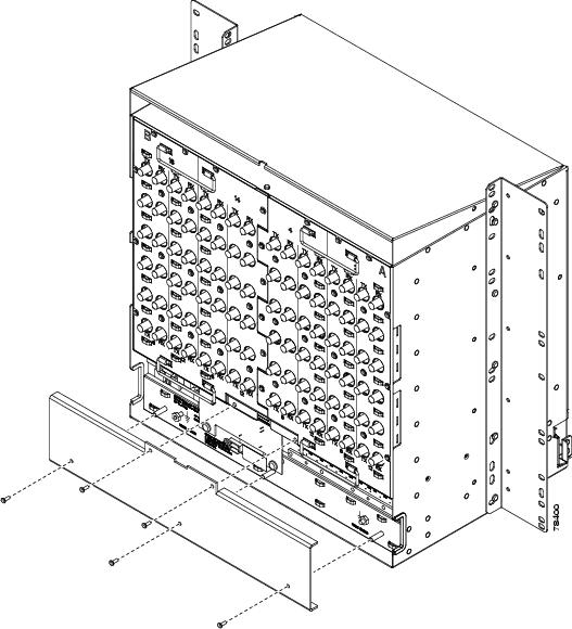
Figure 1 Attaching Plastic Lower Backplane Cover
Step 5
This document is to be used in conjunction with the Cisco ONS 15454 Procedure Guide, Cisco ONS 15454 Reference Manual, and Cisco ONS 15454 Troubleshooting Guide publications.

Copyright © 2003 Cisco Systems, Inc. All rights reserved.
 Feedback