Span loss calculations
A span loss calculation is an optical network measurement that
-
determines the signal power loss between NCS 1020 and NCS 1010 (amplifer) nodes in an optical transmission network,
-
compares the power measurements at transmitter (Tx) and receiver (Rx) ports at the near and far ends of a fiber span, and
-
automatically raises the Span Loss Value Out Of Range alarm when the calculated loss does not fall within configured thresholds.
On a Raman span with Raman tuning enabled, span loss verification reports the following values:
-
Span loss with pumps off: This measurement is the difference in power values between the DFB-Tx/Rx of the remote node and the DFB-Rx/Tx of the local node. This measurement also includes a timestamp. When a Raman span is up, the span loss application latches on to the difference in power between DFB-Tx and DFB-Rx before Raman tuning turns the Raman pumps on.
-
Apparent span loss: This measurement is based on the power values of C band, L band and Optical Service Channel (OSC). For a Raman span, the span loss application uses this span loss value to raise the Span Loss Value Out Of Range alarm.
-
Estimated span loss: This value is based on Raman gain that is achieved by Raman tuning application. Estimated span loss value is based on Raman gain that is achieved when safety loop was closed and tuning was performed. Raman tuning application reports the Raman gain measurement. When you disable Raman tuning, the span loss application does not compute the Estimated span loss.
Estimated span loss = Apparent span loss + Raman gain
-
OSC span loss: This measurement is the difference in OSC power values between the Tx/Rx of the remote node and the Rx/Tx of the local node.
-
Signal span loss: This measurement is the difference in the received C band signal power values between the Tx/Rx of the remote node and the Rx/Tx of the local node.
The span loss application reports the span loss value for a span every 90 seconds. If span loss changes, for example when a change in fiber loss occurs, the span loss application typically takes 90 seconds to update the span loss.
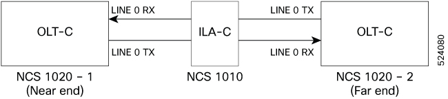
For example, in the previous figure, the Tx Span Loss on NCS 1020-1 is the difference in signal power between LINE 0 Tx on NCS 1020-1 and LINE 0 Rx on NCS 1010.
View span loss values
Use this procedure to display span loss measurements between NCS 1010 nodes. This process helps verify optical signal integrity and diagnose network issues
 Note |
Rx span loss values are not available on a network where one NCS 1010 node is upgraded to R25.3.1 while other nodes are on an earlier software version. |
Procedure
|
Use the show olc span-loss command to view the Tx span loss and Rx span loss. Example:The following sample shows the output of the show olc span-loss command on a Raman span with Raman tuning disabled. In this sample output, Raman tuning is disabled on both Ots0/0/0/0 and Ots0/0/0/2 on the near end node. The far end nodes have Raman tuning enabled. The following sample shows the output of the show olc span-loss command on a non-Raman span. |
Configure Span Loss Thresholds
Use this task to configure span loss thresholds.
Procedure
|
Step 1 |
Select the controller on which the span loss thresholds need to be configured after entering into the optical applications configuration mode. Example: |
|
Step 2 |
Configure the minimum and maximum span loss threshold values. Example:The system raises a SPAN-LOSS-OUT-OF-RANGE alarm if span loss is greater than the maximum threshold or less than the minimum threshold. |
|
Step 3 |
Commit the changes and exit all the configuration modes. Example: |
 Feedback