NCS1K-MD-32x-CE Mux/Demux Passive Patch Panels
|
Feature Name |
Release Information |
Feature Description |
|---|---|---|
|
NCS1K-MD-32x-CE patch panel |
Cisco IOS XR Release 25.1.1 |
The MD-32x-CE patch panels are passive AAWG modules with 32 channels each. They support 150-GHz channel spacing, with a 75-GHz shift between ODD and EVEN panels. Combined, they offer 64 channels with 75-GHz spacing. Each panel supports wide optical pass-band and acts as an add/drop unit for 32 channels at 140 GBd. The supported panels are:
|
 Note |
NCS1K-MD-32x-CE is referred as MD-32x-CE patch panel. |
The MD-32x-CE patch panels are a pair of passive Athermal Arrayed Waveguide Grating (AAWG) based modules. Each mux/demux panel has 32 channels and works as an add/drop unit for the NCS 1001 and NCS 1014 optical line systems. Each mux/demux panel allows the multiplexing and demultiplexing of 32 channels with 150-GHz spacing. 75-GHz frequency shift exists between the ODD and EVEN panels. When both panels are used on the same optical line systems (NCS 1001 or NCS 1014), the combined capacity becomes 64 channels with 75-GHz spacing. Each mux/demux panel provides a wide optical pass-band support. When used as a standalone, each panel acts as an add/drop unit for 32 channels at 140 GBd.
Characteristics of MD-32x-CE
The MD32x-CE patch panel operates in C-band. It is the enhanced version of the NCS1K-MD-32O/E-C patch panel.
|
Functionalities |
NCS1K-MD-32E-CE |
NCS1K-MD-32O-CE |
|---|---|---|
|
Band type |
C-band |
|
|
Loopback |
Loopback is not supported. |
|
|
Frenquency range (THz) |
191.375 - 196.025 |
191.450 - 196.100 |
|
Embedded optical modules |
optical coupler |
optical splitter |
|
Coherent probe testing |
MD32x-CE patch panel has a dedicated PROBE port to detect test probe signal to verify connection with the host card. |
|
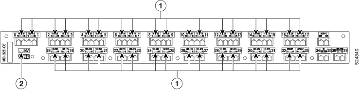
Front panel of the MD-32x-CE
The interfaces of MD-32E-C patch panel is similar to the MD-32-O-CE patch panel.
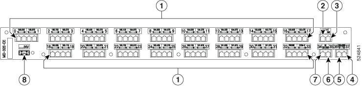
| Callout |
Port label |
Connector type |
Description |
|---|---|---|---|
|
1 |
CH-i TX/RX [i=0–31] |
LC |
Transmits and receives data through the 32 optical channels |
|
COM-x-TX/RX |
LC |
Transmits and receives the combined signals to multiplex or demultiplex. Its operating frequency range is 196.175–191.15 (1528.2–1568.4) [THz (nm)]. |
|
|
PROBE-TX/RX |
LC |
Starts the coherent test probe signal in TX port and detects the signal in RX port to verify connection with the host card |
|
|
2 |
MON-x-MUX |
LC |
Monitors the aggregrated signal flowing out of the patch panel. Its operating frequency range is 196.175–191.15 (1528.2–1568.4) [THz (nm)]. |
|
3 |
MON-x-DEMUX |
LC |
Monitors the aggregrated signal coming into the patch panel to demultiplex the signal. Its operating frequency is the same as MON-x-MUX port. |
|
4 |
ODD+EVEN-TX2 |
LC |
Transmits the ODD and EVEN optical channels |
|
5 |
ODD+EVEN TX1 |
LC |
Transmits the ODD and EVEN optical channels |
|
6 |
RX-EVEN |
LC |
Receives the EVEN optical channels |
|
7 |
RX-ODD |
LC |
Receives the ODD optical channels |
|
8 |
INV |
USB Type A receptacle connector |
Establishes USB communication channel with the optical line system |
Communication with the NCS 1001 and NCS 1014 optical line system
The MD32x-CE patch panels communicate to the optical line system using a USB communication channel. The INV port is the dedicted USB 2.0 port in the patch panels that connect to the controllers to communicate.
The USB communication channel helps to:
-
retrieve the inventory data and the insertion loss of the optical paths.
-
retrieve the optical power levels monitored by the patch panels’ photodiodes.
-
activate an LED on request or other type of displays or electrical actuators.
-
upgrade the patch panels firmware.
Interoperability with EDFA2 line card
NCS1014 node containing an EDFA2 line card and one or more MD-32x-CE patch panels aggregate signals from 2.4T or 2.4TX transponders.
Channel wavelength allocation
The table shows the frequency and wavelength allocated to each channel for both ODD and EVEN version of the MD-32x-C patch panels.
|
Channel Label |
NCS1K-MD-32E-CE |
NCS1K-MD-32O-CE |
||
|---|---|---|---|---|
|
Frequency (THz) |
Wavelength (nm) |
Frequency (THz) |
Wavelength (nm) |
|
|
0 |
196.025 |
1529.36 |
196.100 |
1528.77 |
|
1 |
195.875 |
1530.53 |
195.950 |
1529.94 |
|
2 |
195.725 |
1531.70 |
195.800 |
1531.12 |
|
3 |
195.575 |
1532.88 |
195.650 |
1532.29 |
|
4 |
195.425 |
1534.05 |
195.500 |
1533.47 |
|
5 |
195.275 |
1535.23 |
195.350 |
1534.64 |
|
6 |
195.125 |
1536.41 |
195.200 |
1535.82 |
|
7 |
194.975 |
1537.59 |
195.050 |
1537.00 |
|
8 |
194.825 |
1538.78 |
194.900 |
1538.19 |
|
9 |
194.675 |
1539.96 |
194.750 |
1539.37 |
|
10 |
194.525 |
1541.15 |
194.600 |
1540.56 |
|
11 |
194.375 |
1542.34 |
194.450 |
1541.75 |
|
12 |
194.225 |
1543.53 |
194.300 |
1542.94 |
|
13 |
194.075 |
1544.72 |
194.150 |
1544.13 |
|
14 |
193.925 |
1545.92 |
194.000 |
1545.32 |
|
15 |
193.775 |
1547.12 |
193.850 |
1546.52 |
|
16 |
193.625 |
1548.31 |
193.700 |
1547.72 |
|
17 |
193.475 |
1549.52 |
193.550 |
1548.91 |
|
18 |
193.325 |
1550.72 |
193.400 |
1550.12 |
|
19 |
193.175 |
1551.92 |
193.250 |
1551.32 |
|
20 |
193.025 |
1553.13 |
193.100 |
1552.52 |
|
21 |
192.875 |
1554.34 |
192.950 |
1553.73 |
|
22 |
192.725 |
1555.55 |
192.800 |
1554.94 |
|
23 |
192.575 |
1556.76 |
192.650 |
1556.15 |
|
24 |
192.425 |
1557.97 |
192.500 |
1557.36 |
|
25 |
192.275 |
1559.19 |
192.350 |
1558.58 |
|
26 |
192.125 |
1560.40 |
192.200 |
1559.79 |
|
27 |
191.975 |
1561.62 |
192.050 |
1561.01 |
|
28 |
191.825 |
1562.84 |
191.900 |
1562.23 |
|
29 |
191.675 |
1564.07 |
191.750 |
1563.45 |
|
30 |
191.525 |
1565.29 |
191.600 |
1564.68 |
|
31 |
191.375 |
1566.52 |
191.450 |
1565.90 |
 Feedback