Bring up Cisco NCS 1014

Boot behaviors of Cisco NCS 1014

Boot behaviors of Cisco NCS 1014 are post-installation startup activities that

  • power on the chassis and run the boot process from the pre-installed operating system image,

  • use the iPXE boot or an external bootable USB drive when no valid pre-installed image is available, and

  • establish the root username and password that you use to log on to the XR console.

Table 1. Feature History

Feature Name

Release Information

Feature Description

IPv6 support for protocols

Cisco IOS XR Release 25.1.1

IPv6 addressing is now supported for the protocols such as PXE, DHCP, SCP, HTTP, HTTPS, and NTP which are used to bring up the NCS1014 node. however, PXE does not support IPv6 when using HTTPS.

Configuring IPv6 addresses on the management interfaces is supported, enabling communication between nodes to utilize the extensive address space. Additionally, IPv6 addressing ensures efficient and secure device management.

Boot behavior of Cisco NCS 1014

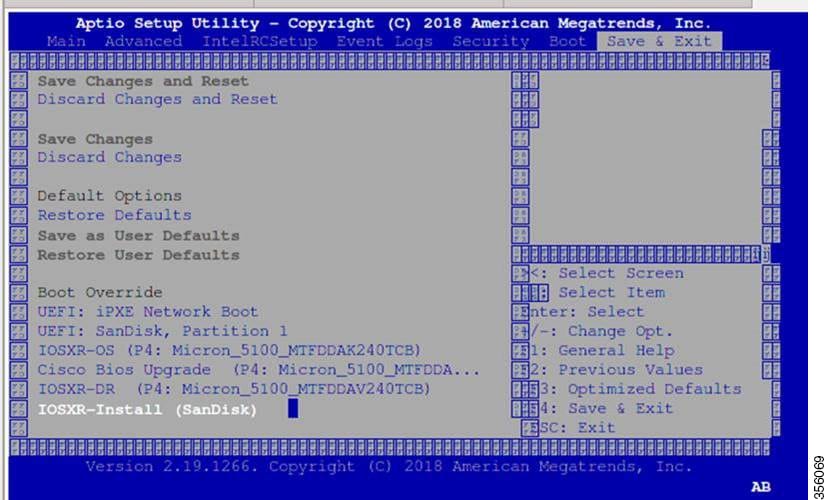
After installing the hardware, boot the Cisco NCS 1014 system. You can connect to the XR console port and power on the system. Cisco NCS 1014 completes the boot process using the pre-installed operating system (OS) image. If no image is available, Cisco NCS 1014 can be booted using the iPXE boot or an external bootable USB drive.

During the first boot, create the root username and password and then use these credentials to log on to the XR console.


Note


The output of the examples in the procedures is not from the latest software release. The output will change for any explicit references to the current release.


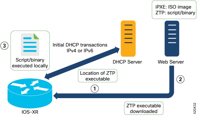
IPv6 support for bring-up protocols

From Release 25.1.1, IPv6 addressing is supported for the protocols used in bringing up the NCS1014 node. These protocols include PXE, DHCP, SCP, HTTP, HTTPS, and NTP.


Note


PXE does not support IPv6 when using HTTPS.


Configuring IPv6 addresses on the management interfaces is supported, enabling communication between nodes to utilize the extensive address space. Additionally, IPv6 addressing ensures efficient and secure device management.

Zero Touch Provisioning

Zero Touch Provisioning (ZTP) is an automated provisioning capability on Cisco NCS 1014 that

  • provisions the network device with day 0 configurations,

  • supports both management ports and data ports, and

  • downloads and applies a configuration file or runs a user script that the DHCP server points to.

What you can do with ZTP

ZTP provides multiple options:

  • Automatically apply specific configuration in a large-scale environment.

  • Download and install specific IOS XR image.

  • Install specific application package or third-party applications automatically.

  • Deploy containers without manual intervention.

  • Upgrade or downgrade software versions effortlessly on thousands of network devices at a time.

Benefits of using ZTP

ZTP helps you manage large-scale service provider infrastructures effortlessly. Following are the added benefits of using ZTP:

  • ZTP helps you to remotely provision a router anywhere in the network. This eliminates the need for an expert to deploy network devices and reduces IT cost.

  • Automated provisioning using ZTP removes delay, increases accuracy, provides better customer experience and is cost-effective. By automating repeated tasks, ZTP allows network administrators to concentrate on more important stuff.

  • ZTP process helps you to quickly restore service. Rather than troubleshooting an issue on hand, you can reset a system to a well-known working status.

Prerequisites for ZTP

ZTP does not execute, if a username is already configured in the system.

Methods to start ZTP

ZTP is initiated through one of the following methods:

  • Automated fresh boot: On booting a device without any prior configuration, ZTP starts automatically. The router receives configuration file details from the DHCP server. This method is used for devices without pre-loaded configuration. Refer to Fresh boot using DHCP.

  • Configuration file: The first line of the configuration file must be "!! IOS XR configuration" for ZTP to process it. If bringing up multiple new nodes, each requires a separate configuration file. Refer to ZTP configuration files.

  • ZTP bootscript: Define a script to execute on every boot for customized automated actions. Refer to ZTP bootscript.

  • Manual invocation using CLI: Use this method to forcefully start ZTP on a fully configured device by running a CLI command. Refer to Invoke ZTP manually through CLI.

  • Invocation using reload command: Use the reload command to start ZTP on a fully configured device. Refer to Invoke ZTP through reload.

How fresh boot using DHCP works

The fresh boot using DHCP starts the ZTP process on a Cisco NCS 1014 device that has no existing configuration. This process automates day 0 provisioning by coordinating DHCP-based discovery, automated file downloads, and applying the necessary configuration or scripts, enabling rapid deployment without manual intervention.

Summary

The key components involved in this process are:

  • Cisco NCS 1014 device: Sends DHCP requests on management and data ports, downloads the configuration or script file, and applies the file or runs the script.

  • DHCP server: Identifies the device through the DHCP options that ZTP sends and responds with the location of the configuration file or script.

  • Web (HTTP) server: Hosts the configuration file or script file that the device downloads using the URL location provided in the DHCP response.

The figure depicts the high-level workflow of the ZTP process.

Workflow

Figure 1. ZTP fresh boot workflow

These stages describe the fresh boot using DHCP:

  1. Z Initiating DHCP requests: ZTP begins by sending DHCP requests to obtain the configuration file or user script. To help the bootstrap server uniquely identify the device, these DHCP options are sent:
    • DHCP(v4/v6) client-id set to the device serial number
    • DHCPv4 option 124 providing the vendor, platform, and serial number
    • DHCPv6 option 16 providing the vendor, platform, and serial number
    DHCP requests are performed in this order:
    • ZTP sends an IPv4 DHCP request to all management ports. If this fails, it follows with an IPv6 request on the same ports.
    • Next, ZTP sends an IPv4 DHCP request on all data ports. If this fails, it follows with an IPv6 request on these ports.
  2. DHCP server response: The DHCP server recognizes the device from the received options and replies with the location of the configuration or script file using one of these DHCP options:
    • DHCPv4 using BOOTP filename.
    • DHCPv4 using Option 67 (bootfile-name).
    • DHCPv6 using Option 59 (OPT_BOOTFILE_URL).
  3. Downloading the file: The device uses the URL from the DHCP response to download the required file (configuration or script) from the web (HTTP) server.
  4. Identifying the downloaded file: The device assesses the file type based on its content:
    • If the downloaded file content starts with !! IOS XR , it is considered as a configuration file.
    • If the downloaded file content starts with #! /bin/bash , #! /bin/sh , or #!/usr/bin/python , it is considered as a script file.
  5. Applying the configuration or running the script: The device either applies the configuration file or runs the script or binary in the default bash shell.
  6. Device is operational: The device is now up and running, fully provisioned with the day 0 configuration or script as directed by the DHCP server.

Result

The Cisco NCS 1014 device completes its initial provisioning and is ready for use, having automatically applied the appropriate configuration or script obtained through the ZTP and DHCP process.

ZTP configuration files

A ZTP configuration file is an IOS XR configuration file that

  • starts with !! IOS XR on the first line so that ZTP processes it as a configuration,

  • contains the day 0 configuration that you want to automate on Cisco NCS 1014, and

  • is downloaded from the DHCP server when ZTP is executed.

You can use either a configuration file or a script file to initiate the ZTP process, based on your business needs. The configuration file must start with !! IOS XR to be recognized by ZTP.

For more information on how to create ZTP configuration files, see ZTP Configuration Files Creation.

Sample ZTP configuration file

The following sample configuration file illustrates how you can automate all IOS XR configurations required during Zero Touch Provisioning:

!! Building configuration
!! IOS XR Configuration 7.11.1.35I
!! Last configuration change at Fri Sep 15 17:18:53 2023 by cisco
!
hostname IOS_P2B_FLT
logging console debugging
username cisco
 group root-lr
 group cisco-support
 secret 10 $6$4gjnzvvwDCz1z...$bovO.6uRYD9qsujiw6DNjTx6bngeDIVMvXxVbReal6bpd0SRo5qyfHk5S4D23r9hjntYtXnyQWNcrgbK0USB20
!
grpc
 port 57400
!
line template vty
 timestamp disable
 exec-timeout 0 0
!
line template test
 exec-timeout 0 0
!
line console
 timeout login response 30
 timestamp
 exec-timeout 0 0
 width 0
 length 0
!
line default
 timestamp disable
 exec-timeout 0 0
 length 0
 absolute-timeout 0
 session-timeout 0
!
vty-pool default 0 10 line-template default
fpd auto-upgrade enable
ntp
 max-associations 99
!
call-home
 service active
 contact smart-licensing
 profile CiscoTAC-1
  active
  destination transport-method email disable
  destination transport-method http
 !
!
netconf-yang agent
 ssh
!
hw-module location 0/1/NXR0
 mxponder-slice 0
  trunk-rate 600G
  client-rate 100GE
 !
!
hw-module location 0/2/NXR0
 mxponder-slice 0
  trunk-rate 800G
  client-port-rate 1 client-type 400GE
 !
!
interface MgmtEth0/RP0/CPU0/0
 description mgmt0
 ipv4 address 10.105.57.64 255.255.255.0
!
interface MgmtEth0/RP0/CPU0/1
 ipv4 address 10.127.60.44 255.255.255.0
 ipv6 enable
!
controller Optics0/0/0/0
 description optics0/0/0/0
 pm 30-sec optics threshold opt min 2
 fastpoll enable
 perf-mon enable
!
controller Optics0/0/0/1
 description optics0/0/0/1
 fastpoll enable
!
controller Optics0/0/0/2
 description optics0/0/0/2
 perf-mon enable
!
controller Optics0/0/0/3
 description optics0/0/0/3
!
controller Optics0/0/0/4
 description optics0/0/0/4
!
controller Optics0/0/0/5
 description optics0/0/0/5
!
controller Optics0/0/0/6
 description optics0/0/0/6
!
controller Optics0/0/0/7
 description optics0/0/0/7
!
controller Optics0/0/0/8
 description optics0/0/0/8
!
controller Optics0/0/0/9
 description optics0/0/0/9
 pm 15-min optics report opt max-tca enable
 pm 15-min optics threshold opt-dbm max -200
 pm 30-sec optics report opr min-tca enable
 pm 30-sec optics report opt max-tca enable
 pm 30-sec optics threshold opr-dbm min 500
 pm 30-sec optics threshold opt-dbm max -210
!
controller Optics0/0/0/10
 description optics0/0/0/10
!
controller Optics0/0/0/11
 description optics0/0/0/11
!
controller Optics0/0/0/12
 description optics0/0/0/12
!
controller Optics0/0/0/13
 description optics0/0/0/13
!
controller Optics0/1/0/0
 description optics0/1/0/0
 pm 15-min optics report opr min-tca enable
 pm 15-min optics threshold opr-dbm min 200
 pm 30-sec optics report opr min-tca enable
 pm 30-sec optics threshold opr-dbm min 200
 fastpoll enable
!
controller Optics0/1/0/1
 description optics0/1/0/1
!
controller Optics0/1/0/2
 description optics0/1/0/2
!
controller Optics0/1/0/3
 description optics0/1/0/3
!
controller Optics0/1/0/4
 description optics0/1/0/4
!
controller Optics0/1/0/5
 description optics0/1/0/5
!
controller Optics0/1/0/6
 description optics0/1/0/6
!
controller Optics0/1/0/7
 description optics0/1/0/7
!
controller Optics0/1/0/8
 description optics0/1/0/8
!
controller Optics0/1/0/9
 description optics0/1/0/9
!
controller Optics0/1/0/10
 description optics0/1/0/10
!
controller Optics0/1/0/11
 description optics0/1/0/11
!
controller Optics0/1/0/12
 description optics0/1/0/12
!
controller Optics0/1/0/13
 description optics0/1/0/13
!
controller Optics0/2/0/0
 description optics0/2/0/0
 transmit-power -25
 dwdm-carrier 100MHz-grid frequency 1923500
 rx-low-threshold -120
 rx-high-threshold 40
 tx-low-threshold -101
 tx-high-threshold 40
!
controller Optics0/2/0/1
 description optics0/2/0/1
!
controller Optics0/2/0/2
 description optics0/2/0/2
!
controller Optics0/2/0/3
 description optics0/2/0/3
!
controller Optics0/2/0/4
 description optics0/2/0/4
!
controller Optics0/2/0/5
 description optics0/2/0/5
!
controller Optics0/2/0/6
 description optics0/2/0/6
!
controller Optics0/2/0/7
 description optics0/2/0/7
!
controller Optics0/3/0/0
 description optics0/3/0/0
!
controller Optics0/3/0/1
 description optics0/3/0/1
!
controller Optics0/3/0/2
 description optics0/3/0/2
 pm 30-sec optics report opr min-tca enable
 pm 30-sec optics threshold opr-dbm min 200
!
controller Optics0/3/0/3
 description optics0/3/0/3
!
controller Optics0/3/0/4
 description optics0/3/0/4
!
controller Optics0/3/0/5
 description optics0/3/0/5
!
controller Optics0/3/0/6
 description optics0/3/0/6
!
controller Optics0/3/0/7
 description optics0/3/0/7
!
controller Optics0/3/0/8
 description optics0/3/0/8
!
controller Optics0/3/0/9
 description optics0/3/0/9
!
controller Optics0/3/0/10
 description optics0/3/0/10
!
controller Optics0/3/0/11
 description optics0/3/0/11
!
controller Optics0/3/0/12
 description optics0/3/0/12
!
controller Optics0/3/0/13
 description optics0/3/0/13
!
interface PTP0/RP0/CPU0/0
 shutdown
!
interface PTP0/RP0/CPU0/1
 shutdown
!
router static
 address-family ipv4 unicast
  0.0.0.0/0 10.105.57.1
  0.0.0.0/0 10.127.60.1
 !
!
snmp-server traps sensor
snmp-server traps fru-ctrl
netconf agent tty
!
lldp
!
ains-soak hours 47 minutes 59
ssh timeout 120
ssh server rate-limit 600
ssh server session-limit 100
ssh server v2
ssh server vrf default
ssh server netconf vrf default
end

ZTP bootscripts

A ZTP bootscript is a downloadable script file that

  • starts with #! /bin/bash or #! /bin/sh on the first line so that ZTP processes it as a script,

  • provides a programmatic way to complete a task such as a patch upgrade using IOS XR commands, and

  • runs every time the device boots when you register it through the ztp bootscript command.

You can either use the ZTP bash script or the ZTP configuration file. ZTP downloads and executes the script files. These script files include a programmatic approach to complete a task. For example, scripts created using IOS XR commands to perform patch upgrades.

Register the bootscript

To manually execute a script during every boot, use this configuration:

RP/0/RP0/CPU0:ios#configure
RP/0/RP0/CPU0:ios(config)#ztp bootscript /disk0:/myscript
RP/0/RP0/CPU0:ios(config)#commit

This configuration waits for the first data plane interface to be configured and waits an extra minute for the management interface to receive an IP address, ensuring connectivity in the third-party namespace. If you do not want this delay, use:

RP/0/RP0/CPU0:ios#configure
RP/0/RP0/CPU0:ios(config)#ztp bootscript preip /disk0:/myscript
RP/0/RP0/CPU0:ios(config)#commit

Note


When the above command is first configured, you are prompted whether you wish to invoke it now. The prompt helps with testing.


Sample content of /disk0:/myscript

host ncs1010_P1B_DT_08_ETH0 {
#hardware ethernet 68:9e:0b:b8:6f:5c ;
option dhcp-client-identifier "FCB2437B05N" ;
if exists user-class and option user-class = "iPXE" {
filename "http://192.0.2.51/P1B_DT_08/ncs1010-x64.iso";
} else {
filename "http://192.0.2.51/P1B_DT_08/startup.cfg";
}
fixed-address 192.0.2.19;
}

Sample ZTP bash script

#! /bin/bash
#
# NCS1014 Demo Sample
# ZTP installation of config and day-0 SMU's
#
source ztp_helper

wget http://downloads.sourceforge.net/project/yourcode/application.tgz
#install the downloaded application.tgz

#Run XR CLI's from the script
`xrcmd "show version"`

Sample ZTP configuration file

Tue May 4 18:08:59.544 UTC
Building configuration...
IOS XR Configuration 7.11.1.35I
!! Last configuration change at Fri Sep 15 17:18:53 2023 by cisco
!
line console
exec-timeout 0 0
!
line default
exec-timeout 0 0
session-timeout 0
!
vty-pool default 0 20
alias alarms show alarms brief system active
interface MgmtEth0/RP0/CPU0/0
ipv4 address dhcp
no shut
!
interface MgmtEth0/RP0/CPU0/1
description noshut-interface-ztp
ipv4 address 10.127.60.160 255.255.255.0
no shut
!
interface PTP0/RP0/CPU0/0
description noshut-interface-ztp
no shut
!
interface PTP0/RP0/CPU0/1
description noshut-interface-ztp
no shut
end

Manually initiate ZTP through CLI on Cisco NCS 1014

Configure ZTP by manually initiating, terminating, or cleaning ZTP sessions using CLI commands on a Cisco NCS 1014 device so you can provision the router in stages or test ZTP without a system reboot.

Use this task to provision the router in stages or test your ZTP configuration without needing to restart the device. You do not need to pre-configure or bring up interfaces beforehand; ZTP commands work on any data or management interface regardless of state and automatically bring up interfaces as needed.

Procedure


Step 1

(Optional) Remove all the ZTP logs and saved settings using the command Initiate a new ZTP session.

Example:

RP/0/RP0/CPU0:ios#ztp clean
Fri Sep 15 17:12:33.477 IST
This would remove all ZTP temporary files.
Would you like to proceed? [no]: yes
All ZTP operation files have been removed.
ZTP logs are present in /var/log/ztp*.log for logrotate.
Please remove manually if needed.
If you now wish ZTP to run again from boot, do 'conf t/commit replace' followed by reload.
RP/0/RP0/CPU0:ios#

Step 2

Reboot the Cisco NCS 1014 system to start a new ZTP session using the command ztp initiate .

Example:

RP/0/RP0/CPU0:ios#ztp initiate
Fri Sep 15 17:13:28.580 IST
Inititaing ZTP may change your configuration.
Interfaces might be brought up if they are in shutdown state
Would you like to proceed? [no]: yes
ZTP will now run in the background.
Please use "show logging" or look at /var/log/ztp.log to check progress.
RP/0/RP0/CPU0:ios#

Step 3

(Optional) Terminate the active ZTP session using the command ztp terminate .

Example:

RP/0/RP0/CPU0:ios#ztp terminate
Fri Sep 15 17:15:04.592 IST
This would terminate active ZTP session if any (this may leave your system in a partially configured state)
Would you like to proceed? [no]: yes
Terminating ZTP
RP/0/RP0/CPU0:ios#

ZTP runs on the specified interfaces of Cisco NCS 1014, and the device is provisioned with the day 0 configuration or script that the DHCP server pointed to.

Force ZTP through reload

Restore the device to its ZTP-initiated state by wiping the running configuration, cleaning ZTP logs and saved settings, and rebooting the system.

Use this task to automatically invoke the ZTP process on a Cisco NCS 1014 device by performing a reload. This operation is valuable when you need to re-provision a device or return it to its default, fully provisioned state.

Procedure


Step 1

Enter the configuration mode.

configure

Example:

RP/0/RP0/CPU0:P2B_DT_02#configure

Step 2

Remove the entire running configuration.

commit replace

Example:

RP/0/RP0/CPU0:ios(config)#commit replace
Fri Sep 15 11:47:31.746 UTC

This commit will replace or remove the entire running configuration. This
operation can be service affecting.
Do you wish to proceed? [no]: yes
RP/0/RP0/CPU0:ios(config)#

Step 3

Remove all the ZTP logs and saved settings.

ztp clean

Example:

RP/0/RP0/CPU0:ios#ztp clean
Fri Sep 15 11:48:13.669 UTC
This would remove all ZTP temporary files.
Would you like to proceed? [no]: yes
All ZTP operation files have been removed.
ZTP logs are present in /var/log/ztp*.log for logrotate.
Please remove manually if needed.
If you now wish ZTP to run again from boot, do 'conf t/commit replace' followed by reload.
RP/0/RP0/CPU0:ios#

Step 4

Reboot the Cisco NCS 1014 system.

reload

After the node comes up, you can see that the ZTP is initiated and the configuration is restored successfully.

Example:

RP/0/RP0/CPU0:ios#reload
Fri Apr 29 06:50:12.312 UTC
Proceed with reload? [confirm]

RP/0/RP0/CPU0:ios#
Preparing system for backup. This may take a few minutes especially for large configurations.
	Status report: node0_RP0_CPU0: BACKUP INPROGRESS
	Status report: node0_RP0_CPU0: BACKUP HAS COMPLETED SUCCESSFULLY
[Done]

RP/0/RP0/CPU0:Sep 25 17:29:19.875 UTC: pyztp2[325]: %INFRA-ZTP-4-START : ZTP has started. Interfaces might be brought up if they are shutdown
RP/0/RP0/CPU0:Sep 25 17:30:33.286 UTC: pyztp2[325]: %INFRA-ZTP-6-DISCOVERY_COMPLETED : Discovery successful on MgmtDhcp4Fetcher. Will proceed with fetching.
RP/0/RP0/CPU0:Sep 25 17:30:47.362 UTC: pyztp2[325]: %INFRA-ZTP-6-FETCHING_COMPLETED : Provisioning file fetched successfully
RP/0/RP0/CPU0:Sep 25 17:31:30.889 UTC: pyztp2[325]: %INFRA-ZTP-4-CONFIG_INITIATED : ZTP has initiated config load and commit operations
RP/0/RP0/CPU0:Sep 25 17:32:36.100 UTC: pyztp2[325]: %INFRA-ZTP-4-CONFIG_FINISHED : ZTP has finished config load and commit operations
RP/0/RP0/CPU0:Sep 25 17:32:41.059 UTC: pyztp2[325]: %INFRA-ZTP-6-CFG_TAMP_SAVE_HASH : Config hash saved after ztp Config is: (643013d9a43a3d2576012a24eb9745a8f960480d0053d06ed81146cb3c3d54c5).
RP/0/RP0/CPU0:Sep 25 17:32:44.089 UTC: pyztp2[325]: %INFRA-ZTP-4-PROVISIONING_COMPLETED : ZTP has successfully completed the provisioning
RP/0/RP0/CPU0:Sep 25 17:32:52.909 UTC: pyztp2[325]: %INFRA-ZTP-4-EXITED : ZTP exited
User Access Verification

Username: cisco
Password:
ios con0/RP0/CPU0 is now available

The ZTP process is initiated on Cisco NCS 1014, the configuration is restored, and the device returns to a fully provisioned state.

Log files for ZTP operations on Cisco NCS 1014

ZTP records all provisioning activities on the flash file system in the /disk0:/ztp/ directory. The log captures every transaction with the DHCP server and tracks all state transitions throughout the provisioning process.

This is a sample excerpt from a ZTP log obtained during the execution of a simple configuration script that was downloaded from a data interface. The script unshuts all system interfaces and sets a load interval of 30 seconds on each interface.

2023-09-25 17:37:31,693  28136 [Engine       ] DEB: ZAdmin, current state:active. Processing work: Sending standby sync message. done = False
2023-09-25 17:37:31,716  28136 [Engine       ] DEB: ZAdmin, current state:active. Processing work: [privileged] getting engine status. done = False
2023-09-25 17:37:31,717  28136 [Engine       ] DEB: ZAdmin, current state:active. Processing work: Fetching provisioning data. done = False
2023-09-25 17:37:31,718  28136 [Engine       ] INF: ZAdmin, current state:active: state tag changed to fetch
2023-09-25 17:37:31,721  28136 [Xr           ] INF: Downloading the file to /tmp/ztp.script
2023-09-25 17:37:31,948  28136 [ReportBootz  ] INF: User script downloaded successfully. Provisioning in progress.
2023-09-25 17:37:31,950  28136 [Engine       ] DEB: ZAdmin, current state:active. Processing work: Config device work for ZAdmin. done = False
2023-09-25 17:37:31,951  28136 [ZtpHelpers   ] DEB: Executing: source /pkg/bin/ztp_helper.sh && echo -ne  | xrcmd "show version"
2023-09-25 17:37:32,956  28136 [ZAdmin       ] DEB: Proceeding to provision the router
2023-09-25 17:37:32,958  28136 [Engine       ] DEB: ZAdmin, current state:active. Processing work: ZAdmin: Apply configuration. done = False
2023-09-25 17:37:32,959  28136 [Engine       ] INF: ZAdmin, current state:active: state tag changed to provision
2023-09-25 17:37:32,975  28136 [Env          ] DEB: No MTU configs detected
2023-09-25 17:37:32,977  28136 [Engine       ] DEB: ZAdmin, current state:active. Processing work: ZAdmin: Apply configuration. done = False
2023-09-25 17:37:33,021  28136 [Xr           ] DEB: Will apply the following config: /disk0:/ztp/customer/config.candidate
2023-09-25 17:37:33,022  28136 [Xr           ] INF: Applying user configurations
2023-09-25 17:37:33,023  28136 [Configuration] INF: Provisioning via config replace
2023-09-25 17:38:14,445  28136 [Configuration] INF: Configuration has been applied
2023-09-25 17:38:14,447  28136 [Env          ] DEB: cfg::createRefOnConfigCommit: called
2023-09-25 17:38:15,778  28136 [Env          ] DEB: cfg:: Generating hash for File name: /disk0:/ztp/customer/config.inithash_tmp
2023-09-25 17:38:15,780  28136 [Env          ] DEB: cfg::_generateCfgAndSaveHash:: HASH : 643013d9a43a3d2576012a24eb9745a8f960480d0053d06ed81146cb3c3d54c5, type : 1
2023-09-25 17:38:17,743  28136 [Env          ] DEB: cfg::getRefOnConfigCommit: called
2023-09-25 17:38:17,818  28136 [Env          ] DEB: cfg::getRefOnConfigCommit :: ret : data : 643013d9a43a3d2576012a24eb9745a8f960480d0053d06ed81146cb3c3d54c5, len: 64
2023-09-25 17:38:17,819  28136 [Env          ] INF: Env::getConfigRefHashOnCommit: get data from tam : success:b'643013d9a43a3d2576012a24eb9745a8f960480d0053d06ed81146cb3c3d54c5'
2023-09-25 17:38:17,821  28136 [Engine       ] DEB: ZAdmin, current state:active. Processing work: Sending standby sync message. done = False
2023-09-25 17:38:17,836  28136 [Engine       ] DEB: ZAdmin, current state:active. Processing work: [privileged] getting engine status. done = False
2023-09-25 17:38:17,837  28136 [Engine       ] DEB: ZAdmin, current state:active. Processing work: ZAdmin: Execute post-configuration script. done = False
2023-09-25 17:38:17,873  28136 [Env          ] INF: Env::cleanup, success:True, exiting:False
2023-09-25 17:38:17,876  28136 [ZtpHelpers   ] DEB: Executing: source /pkg/bin/ztp_helper.sh && echo -ne  | xrcmd "show running-config"
2023-09-25 17:38:19,582  28136 [Env          ] INF: Executing command ip netns exec vrf-default /sbin/dhclient -4 -cf /etc/dhcp/dhclient.conf.ztp -lf /var/lib/dhcp/dhclient.leases.ztp -sf /etc/dhcp/dhclient-script.ztp2 -r Mg0_RP0_CPU0_0 to release IP
2023-09-25 17:38:20,695  28136 [Xr           ] INF: Removing linux route with ip 10.105.57.107
2023-09-25 17:38:20,731  28136 [Xr           ] INF: Failed to remove default route to to_xr via 10.105.57.107 with error: Error: RTNETLINK answers: No such process encountered while executing command: ip netns exec vrf-default ip route del default dev to_xr src 10.105.57.107 metric 512
2023-09-25 17:38:20,736  28136 [Engine       ] INF: ZAdmin, current state:active, exit code:success
2023-09-25 17:38:20,737  28136 [Engine       ] INF: ZAdmin, current state:final, exit code:success: state changed to final
2023-09-25 17:38:22,846  28136 [Engine       ] DEB: ZAdmin, current state:final, exit code:success. Processing work: Sending standby sync message. done = False
2023-09-25 17:38:22,847  28136 [Engine       ] WAR: ZAdmin, current state:final, exit code:success: work is ignored: work=<desc='Sending standby sync message' done=False priv=False>
2023-09-25 17:38:22,848  28136 [Engine       ] DEB: ZAdmin, current state:final, exit code:success. Processing work: [privileged] getting engine status. done = False
2023-09-25 17:38:27,853  28136 [__main__     ] DEB: Moved to final state
2023-09-25 17:38:27,854  28136 [__main__     ] DEB: ZTP completed successfully
2023-09-25 17:38:27,855  28136 [__main__     ] INF: Exiting SUCCESSFULLY

Tech support information for ZTP on Cisco NCS 1014

Tech support information for Zero Touch Provisioning on Cisco NCS 1014

Command to gather ZTP debugging information

Run the show tech-support ztp command to collect all debugging information of the ZTP process.

RP/0/RP0/CPU0:ios#show tech-support ztp
Thu Jul 28 08:33:27.531 UTC
++ Show tech start time: 2022-Jul-28.083327.UTC ++
Thu Jul 28 08:33:28 UTC 2022 Waiting for gathering to complete
..
Thu Jul 28 08:33:34 UTC 2022 Compressing show tech output
Show tech output available at 0/RP0/CPU0 : /harddisk:/showtech/showtech-R1-ZTP-2022-Jul-28.083327.UTC.tgz
++ Show tech end time: 2022-Jul-28.083334.UTC ++
RP/0/RP0/CPU0:ios#

In this example, the tech support information is saved as a .tgz file in the specified location. You can share this information with the Cisco technical support representative for troubleshooting the ZTP process.

Configure a management interface

Use this task to configure the management interface on Cisco NCS 1014 when the chassis is not booted using ZTP.

The management interface enables system management and remote communication. Assigning an IP address and subnet mask allows for system management, while configuring a static route enables communication with devices on other networks.

Before you begin

  • Obtain the IP addresses and subnet mask for the management interface from your network administrator.

  • Verify that the management interface is connected to the management network.

Procedure


Step 1

Enter IOS XR configuration mode.

Example:

RP/0/RP0/CPU0:ios#configure

Step 2

Enter interface configuration mode for the management interface using the command interface mgmtEth rack/slot/instance/port

Example:

RP/0/RP0/CPU0:ios(config)#interface mgmtEth 0/RP0/CPU0/0

Step 3

Assign an IP address and a subnet mask to the management interface using the command ipv4 address ipv4-address subnet-mask .

Example:

RP/0/RP0/CPU0:ios(config-if)#ipv4 address 10.1.1.1 255.0.0.0

Step 4

Place the management interface in an up state.

Example:

RP/0/RP0/CPU0:ios(config-if)#no shutdown

Step 5

Exit the management interface configuration mode.

Example:

RP/0/RP0/CPU0:ios(config-if)#exit

Step 6

Specify the IP address of the default gateway to configure a static route using the command router static address-family ipv4 unicast 0.0.0.0/0 default-gateway . This IP address is used for communication with devices on other networks.

Example:

RP/0/RP0/CPU0:ios(config)#router static address-family ipv4 unicast 0.0.0.0/0 10.25.0.1

Step 7

Save the configuration changes by using the commit or end command.


The management interface of Cisco NCS 1014 is configured with an IP address, subnet mask, and a static route to the default gateway.

What to do next

Connect the management interface to the Ethernet network. Establish an SSH or Telnet connection to the management interface using its IP address.

Boot the Cisco NCS 1014 through the console port

Boot the Cisco NCS 1014 system and complete the initial setup through the console port.

Use the console port to connect to Cisco NCS 1014. By default, the console port connects to XR mode. Once the management port is configured, you can use it for subsequent connections.

Procedure


Step 1

Connect a terminal to the console port of the RP.

Step 2

Start the terminal emulation program on your workstation.

The console settings are 115200 bps for NCS1K14-CNTLR-K9, 9600 bps for NCS1K14-CTLR-B-K9, 8 data bits, 1 stop bit, and no parity.

Step 3

Power on the Cisco NCS 1014.

To power on the shelves, install the AC or DC power supplies and cables. As Cisco NCS 1014 boots up, you can view the boot process details at the console of the terminal emulation program.

Step 4

Press Enter.

The boot process is complete when the system prompts you to enter the root-system username. If the prompt does not appear, wait for a while to give Cisco NCS 1014 more time to complete the initial boot procedure; then press Enter.

Note


If the boot process fails, it may be because the preinstalled image on the Cisco NCS 1014 is corrupt. In this case, you can boot Cisco NCS 1014 using an external bootable USB drive.


Cisco NCS 1014 completes the boot process and prompts you to create the root-system username for logging on to the XR console.

Boot Cisco NCS 1014 using a USB drive

Boot Cisco NCS 1014 using a bootable USB drive to reimage the system for upgrade or recovery.

A bootable USB drive allows you to reimage Cisco NCS 1014 for a system upgrade or to recover from a boot failure. The drive is prepared by copying a compressed boot file onto it and extracting the contents. Preparation steps can be performed with Windows, Linux, or Mac operating systems.

Before you begin

  • Obtain a USB drive with a minimum storage capacity of 4 GB.

  • Make sure the USB drive has a single partition.
  • Copy the compressed boot file from the software download page at Cisco.com to your local machine. The filename for the compressed boot file is in the format ncs1010-x64-usb-(release_number).zip.

Procedure


Step 1

Prepare a bootable USB drive on your local machine:

  1. Connect the USB drive to your local machine and format it with the FAT32 file system.

  2. Copy the compressed boot file to the USB drive.

  3. Verify that the copy operation is successful.

    To verify, compare the file size at source and destination. Also, verify the MD5 checksum value.

  4. Extract the content of the compressed boot file by unzipping it in the USB drive.

    Extracting the content makes the USB drive a bootable drive.

    Note


    You must extract the contents of the zipped file ("EFI" and "boot" directories) directly in the root folder of the USB drive. If the unzipping application places the extracted files in a new folder, move the "EFI" and "boot" directories to the root folder of the USB drive.

Step 2

Boot Cisco NCS 1014 from the bootable USB drive. For more information, see Boot Cisco NCS 1014 from a USB drive.

  1. Insert the USB drive in one of the USB ports of Cisco NCS 1014.

  2. Reboot Cisco NCS 1014 using power cycle or console.

    Note


    Use the reload bootmedia usb noprompt command to boot the Cisco NCS 1014 from the USB. If you are using the reload bootmedia usb noprompt command, then you can skip the remaining steps.

  3. Press Esc to enter BIOS.

  4. Select the Save & Exit tab of BIOS.

    Figure 2. BIOS page
  5. Select IOS -XR Install.

    The BIOS UI displays the USB drive vendor in the brackets, in this case, SMART USB 1084.

    The system detects USB and boots the image from USB.

    Booting from USB..
    Loading Kernel..
    Verifying (loop)/boot/bzImage...
    (loop)/boot/bzImage verified using attached signature.
    Loading initrd..
    Verifying (loop)/boot/initrd.img...
    
  6. Remove the USB drive after the Rebooting the system after installation message is displayed.

    Cisco NCS 1014 reboots automatically.

    Note


    The USB must be removed only after the image is loaded successfully.


Cisco NCS 1014 boots from the USB drive and starts the IOS XR installation.

iPXE boot methods

A iPXE boot method is a system firmware process that

  • operates at the UEFI level using the network card of management interfaces,

  • enables you to reimage the Cisco NCS 1014 or boot the chassis in case of missing or failed bootable partitions, and

  • downloads and installs the ISO image, then bootstraps the system into the new installation.

iPXE acts as a bootloader and provides the flexibility to choose the image that the system will boot based on the Platform Identifier (PID), the Serial Number, or the management mac-address. You must define iPXE in the DHCP server configuration file.

iPXE boot methods


Note


The time taken for iPXE to download the ISO image depends on the network speed. Ensure that the network speed is sufficient to complete the image download in less than 10 minutes. The chassis reloads if the image is not downloaded by 10 minutes.


To start the iPXE boot process, use one of these methods.

  • Preferred method: Run either the reload bootmedia network location all command or the reload bootmedia network location 0/RP0 command.

  • Alternative method: Power cycle the Cisco NCS 1014 chassis and start the iPXE boot process in the BIOS interface.


Note


Software installation using iPXE boot with IPv6 is not supported.


Configure the DHCP server

Set up a DHCP server for IPv4, IPv6, or both protocols so that iPXE can boot Cisco NCS 1014.

A DHCP server is essential for the iPXE boot process and must be configured to support either IPv4, IPv6, or both. This configuration allows the network client to obtain the necessary boot and provisioning files automatically.


Note


For DHCPv6, a routing advertisement (RA) message must be sent to all nodes in the network to indicate which method is to be used to obtain the IPv6 address. Configure the Router-advertise-daemon (radvd, install using yum install radvd ) to allow the client to send the DHCP request. For example:

interface eth3
{
        AdvSendAdvert on;
        MinRtrAdvInterval 60;
        MaxRtrAdvInterval 180;
        AdvManagedFlag on;
        AdvOtherConfigFlag on;
        prefix 2001:1851:c622:1::/64
        {
                AdvOnLink on;
                AdvAutonomous on;
                AdvRouterAddr off;
        };
};

Procedure


Step 1

Create the dhcpd.conf file (for IPv4, IPv6, or both communication protocols), the dhcpv6.conf file (for IPv6), or both, in the /etc/ directory.

This configuration file stores the network information such as the path to the script, the location of the ISO install file, the location of the provisioning configuration file, the serial number, and the MAC address of the chassis.

Step 2

Test the server when the DHCP server is running.

For IPv4, you can test the server by using either the MAC address or the serial number of the chassis:

  • Use the MAC address of the chassis and ensure that the configuration is successful.

  • Use the serial number of the chassis. The serial number of the chassis is derived from the BIOS and is used as an identifier.

    host demo {
    option dhcp-client-identifier "<chassis-serial-number>";
      filename "http://<IP-address>/<hardware-platform>-mini-x.iso";
      fixed-address <IP-address>;
    }

    Example

    
    host 10.89.205.202 {
           hardware ethernet 40:55:39:xx:xx:xx;
            option dhcp-client-identifier "<FCB2437B066>";
              if exists user-class and option user-class = "iPXE" {
              filename "http://10.89.205.127/box1/ncs1010-x64.iso";
           } else {
               filename "http://10.89.205.127/box1/StartupConfig.cfg";
           }
           fixed-address 10.89.205.202;
        }
    

The DHCP server is configured and is ready to respond to iPXE boot requests from Cisco NCS 1014.

Boot the Cisco NCS 1014 using iPXE

Enable network boot and reimage of the Cisco NCS 1014 using iPXE.

Use this task to boot the Cisco NCS 1014 from the network with iPXE for reimaging, using either the command-line interface or BIOS selections.

Before you begin

Before you perform the iPXE boot, ensure that:

  • The DHCP server is set and running.

  • The management port of the Cisco NCS 1014 chassis is in the UP state.

Procedure


Step 1

Run the reload bootmedia network location all command or the reload bootmedia network location 0/RP0 command to initiate the iPXE boot process and reimage the chassis.

Example:

RP/0/RP0/CPU0:ios#reload bootmedia network location all
Mon Dec  4 09:49:14.220 UTC
Proceed with reload? [confirm]
Preparing system for backup. This may take a few minutes especially for large configurations.
	Status report: node0_RP0_CPU0: BACKUP INPROGRESS
	Status report: node0_RP0_CPU0: BACKUP HAS COMPLETED SUCCESSFULLY
[Done]

[ 3490.493853] systemd-shutdown[1]: Could not detach DM /dev/dm-9: Device or resource busy
[ 3490.601094] systemd-shutdown[1]: Could not detach DM /dev/dm-8: Device or resource busy
[ 3490.710401] systemd-shutdown[1]: Could not detach DM /dev/dm-7: Device or resource busy
[ 3490.849417] systemd-shutdown[1]: Failed to finalize  DM devices, ignoring
[ 3492.144874] Unsupported TPM Send Cmd! tpm_tag=8001,tpm_ordinal=0145
[ 3492.229149] tpm tpm0: tpm_try_transmit: send(): error -11
[ 3492.307885] reboot: Restarting system
Shelf Assembly Reset
NCS1014, Initializing Devices
Booting from Primary Flash
Aldrin: Programmed MI 4
Continue boot...
Version 2.19.1266. Copyright (C) 2023 American Megatrends, Inc.
BIOS Date: 10/06/2023 16:47:27 Ver: 0ACHI0480
Press <DEL> or <ESC> to enter setup.
TAM: Chip DB Verified

Software Boot OK, Validated
iPXE initialising devices...ok

iPXE 1.0.0+ (8b3e3) -- Open Source Network Boot Firmware -- http://ipxe.org
Features: DNS HTTP HTTPS TFTP VLAN EFI ISO9660 ISO9660_grub Menu
Trying net0-2051 and net0-2052...
net0-2051: 40:14:82:ba:d1:42 using NII on NII-0000:06:00.0 (open)
  [Link:down, TX:0 TXE:0 RX:0 RXE:0]
  [Link status: Unknown (http://ipxe.org/1a086194)]

Example:

RP/0/RP0/CPU0:sanity_176#reload bootmedia network location 0/RP0
Mon Feb 10 16:34:42.282 IST
Proceed with reload? [confirm]

RP/0/RP0/CPU0:Feb 10 16:34:44.277 IST: shelfmgr_exec_cli[65652]: %PLATFORM-SHELFMGR-6-USER_OP : User mols requested 'PXE reimage' of 0/RP0
RP/0/RP0/CPU0:Feb 10 16:34:44.284 IST: processmgr[51]: %OS-SYSMGR-6-INFO : Received request for graceful go-down from shelfmgr. Reload Reason:User initiated card reimage-network. Timeout 55

Preparing system for backup. This may take a few minutes especially for large configurations.
RP/0/RP0/CPU0:Feb 10 16:34:44.284 IST: processmgr[51]: %OS-SYSMGR-6-INFO : Prepared RMF to reboot
	Status report: node0_RP0_CPU0: BACKUP INPROGRESS
RP/0/RP0/CPU0:sanity_176#	Status report: node0_RP0_CPU0: BACKUP HAS COMPLETED SUCCESSFULLY
[Done]
RP/0/RP0/CPU0:Feb 10 16:34:45.974 IST: obflmgr[317]: %PLATFORM-OBFL-6-INFO : Unmounted OBFL directory for 0/Rack
RP/0/RP0/CPU0:Feb 10 16:34:46.225 IST: obflmgr[317]: %PLATFORM-OBFL-6-INFO : Unmounted OBFL directory for 0/RP0/CPU0
RP/0/RP0/CPU0:Feb 10 16:34:46.555 IST: processmgr[51]: %MGBL-SCONBKUP-6-INTERNAL_INFO : Reload debug script successfully spawned
--
--
[438336.926067] reboot: Restarting system


..         *** Cisco ***
System Initializing..
..


Initializing Devices

Booting from Primary Flash
MI: Skipping reprogram
Version 2.19.1266. Copyright (C) 2024 American Megatrends, Inc.
BIOS Date: 10/28/2024 12:47:04 Ver: 0ACHI0500
Press <DEL> or <ESC> to enter setup.
TAM: Chip DB Verified

Software Boot OK, Validated

iPXE initialising devices...ok

iPXE 1.0.0+ (8b3e3) -- Open Source Network Boot Firmware -- http://ipxe.org
Features: DNS HTTP HTTPS TFTP VLAN EFI ISO9660 ISO9660_grub Menu
Trying net0-2051 and net0-2052...
net0-2051: 9c:38:18:88:a4:1d using NII on NII-0000:06:00.0 (open)
  [Link:down, TX:0 TXE:0 RX:0 RXE:0]
  [Link status: Unknown (http://ipxe.org/1a086194)]
Configuring (net0-2051 9c:38:18:88:a4:1d)...... ok
--
--
net0-2052: fe80::9e38:18ff:fe88:a41e/64
Filename: http://4.25.30.34/Kepler/25_1_1_Images/ncs1010-x64.iso
http://4.25.30.34/Kepler/25_1_1_Images/ncs1010-x64.iso... ok
ncs1010-x64.iso : 1810485248 bytes
Booting /EFI/BOOT/bootx64.efi
Welcome to GRUB!

Step 2

Aternatively, initiate the boot process using the BIOS interface.

  1. Reboot Cisco NCS 1014 using power cycle or console.

  2. Press Esc to enter BIOS.

  3. Select the Save & Exit tab of BIOS.

  4. Choose UEFI: iPXE Network Boot.

Example:

TAM: Chip DB Verified
Software Boot OK, Validated
iPXE initialising devices...ok
iPXE 1.0.0+ (8b3e3) -- Open Source Network Boot Firmware -- http://ipxe.org
Features: DNS HTTP HTTPS TFTP VLAN EFI ISO9660 ISO9660_grub Menu
Trying net0-2051 and net0-2052...
net0-2051: 9c:38:18:88:a4:1d using NII on NII-0000:06:00.0 (open)
[Link:down, TX:0 TXE:0 RX:0 RXE:0]
[Link status: Unknown (http://ipxe.org/1a086194)]
Configuring (net0-2051 9c:38:18:88:a4:1d)...... ok
net0: fe80::9e38:18ff:fe88:a41d/64
net1: fe80::9e38:18ff:fe88:a420/64 (inaccessible)
net2: fe80::9e38:18ff:fe88:a421/64 (inaccessible)
net3: fe80::9e38:18ff:fe88:a422/64 (inaccessible)
net0-2051: 4.25.9.3/255.255.0.0 gw 4.25.0.1
net0-2051: fe80::9e38:18ff:fe88:a41d/64
net0-2052: fe80::9e38:18ff:fe88:a41e/64
Filename: http://4.25.30.34/Kepler/25_1_1_Images/ncs1010-x64.iso
http://4.25.30.34/Kepler/25_1_1_Images/ncs1010-x64.iso... ok
ncs1010-x64.iso : 1810485248 bytes
Booting /EFI/BOOT/bootx64.efi
Welcome to GRUB!
/EndEntire
error: no such device: ((cd0)/EFI/BOOT)/EFI/BOOT/grub.cfg.
Verifying (cd0)/EFI/BOOT/grub.cfg...
(cd0)/EFI/BOOT/grub.cfg verified using Pkcs7 signature.

The Cisco NCS 1014 successfully initiates the iPXE network boot process, loading the designated image and displaying boot confirmation messages. Once complete, the system is ready for further installation or configuration.

Insert and verify operation of a Cisco NCS 1014 line card

Install the Cisco NCS 1014 line card and ensure it becomes fully operational within the chassis.

Use this task whenever you add or replace a Cisco NCS 1014 line card. These steps confirm physical installation, operating status, environmental health, and that firmware is current.

Procedure


Step 1

Insert the line card into the slot.

Step 2

Wait until the line card LED turns green.

Step 3

Check that the PID is in OPERATIONAL status using the show platform command.

Example:

CCMD-16-C and CCM-16-L line cards:

RP/0/RP0/CPU0:ios#show platform
Fri Sep 22 06:56:28.653 UTC
Node              Type                     State                    Config state
--------------------------------------------------------------------------------
0/RP0/CPU0        NCS1K14-CNTLR-K9(Active) IOS XR RUN               NSHUT,NMON
0/PM0             NCS1K4-AC-PSU            OPERATIONAL              NSHUT,NMON
0/FT0             NCS1K14-FAN              OPERATIONAL              NSHUT,NMON
0/FT1             NCS1K14-FAN              OPERATIONAL              NSHUT,NMON
0/FT2             NCS1K14-FAN              OPERATIONAL              NSHUT,NMON
0/0/NXR0          NCS1K14-CCMD-16-L        OPERATIONAL              NSHUT,NMON
0/2/NXR0          NCS1K14-CCMD-16-C        OPERATIONAL              NSHUT,NMON
0/3/NXR0          NCS1K14-CCMD-16-C        OPERATIONAL              NSHUT,NMON

Example:

2.4T line card:

RP/0/RP0/CPU0:ios#show platform
Fri Sep 22 06:56:28.653 UTC
Node              Type                     State                    Config state
--------------------------------------------------------------------------------
0/RP0/CPU0        NCS1K14-CNTLR-K9(Active) IOS XR RUN               NSHUT,NMON
0/PM0             NCS1K4-AC-PSU            OPERATIONAL              NSHUT,NMON
0/FT0             NCS1K14-FAN              OPERATIONAL              NSHUT,NMON
0/FT1             NCS1K14-FAN              OPERATIONAL              NSHUT,NMON
0/FT2             NCS1K14-FAN              OPERATIONAL              NSHUT,NMON
0/2/NXR0          NCS1K14-2.4T-K9          OPERATIONAL              NSHUT,NMON
0/3/NXR0          NCS1K14-BLANK             PRESENT                 NSHUT,NMON

Example:

2.4TX line card:

RP/0/RP0/CPU0:ios#show platform
Node              Type                     State                    Config state
--------------------------------------------------------------------------------
0/RP0/CPU0        NCS1K14-CNTLR-K9(Active) IOS XR RUN               NSHUT,NMON
0/PM0             NCS1K4-AC-PSU-2           OPERATIONAL             NSHUT,NMON
0/FT0             NCS1K14-FAN              OPERATIONAL              NSHUT,NMON
0/FT1             NCS1K14-FAN              OPERATIONAL              NSHUT,NMON
0/FT2             NCS1K14-FAN              OPERATIONAL              NSHUT,NMON
0/0/NXR0          NCS1K14-2.4T-X-K9        OPERATIONAL              NSHUT,NMON
0/1/NXR0          NCS1K14-2.4T-X-K9        OPERATIONAL              NSHUT,NMON
0/2/NXR0          NCS1K14-2.4T-X-K9        OPERATIONAL              NSHUT,NMON
0/3/NXR0          NCS1K14-2.4T-X-K9        OPERATIONAL              NSHUT,NMON

Example:

EDFA2 line card:

RP/0/RP0/CPU0:sanity_176#show platform
Node              Type                     State                    Config state
--------------------------------------------------------------------------------
0/RP0/CPU0        NCS1K14-CNTLR-K9(Active) IOS XR RUN               NSHUT,NMON
0/PM0             NCS1K4-AC-PSU-2          OPERATIONAL              NSHUT,NMON
0/PM1             NCS1K4-AC-PSU-2          OPERATIONAL              NSHUT,NMON
0/FT0             NCS1K14-FAN              OPERATIONAL              NSHUT,NMON
0/FT1             NCS1K14-FAN              OPERATIONAL              NSHUT,NMON
0/FT2             NCS1K14-FAN              OPERATIONAL              NSHUT,NMON
0/0/NXR0          NCS1K14-BLANK            PRESENT                  NSHUT,NMON
0/1/NXR0          NCS1K4-1.2T-K9           OPERATIONAL              NSHUT,NMON
0/2/NXR0          NCS1K14-BLANK            PRESENT                  NSHUT,NMON
0/3/NXR0          NCS1K14-EDFA2            OPERATIONAL              NSHUT,NMON
0/4               NCS1K-MD-32O-CE          OPERATIONAL              NSHUT,NMON
0/5               NCS1K-MD-32E-CE          OPERATIONAL              NSHUT,NMON

Example:

2.4TA line card:

RP/0/RP0/CPU0:ios#show platform
Mon Jan 12 11:36:27.652 UTC
Node              Type                     State                    Config state
--------------------------------------------------------------------------------
0/RP0/CPU0        NCS1K14-CNT-B-K9(Active) IOS XR RUN               NSHUT,NMON
0/PM1             NCS1K4-AC-PSU            OPERATIONAL              NSHUT,NMON
0/FT0             NCS1K14-FAN              OPERATIONAL              NSHUT,NMON
0/FT1             NCS1K14-FAN              OPERATIONAL              NSHUT,NMON
0/FT2             NCS1K14-FAN              OPERATIONAL              NSHUT,NMON
0/0/NXR0          NCS1K14-BLANK            PRESENT                  NSHUT,NMON
0/1/NXR0          NCS1K14-2.4T-A-K9        OPERATIONAL              NSHUT,NMON
0/2/NXR0          NCS1K14-2.4T-A-K9        OPERATIONAL              NSHUT,NMON
0/3/NXR0          NCS1K14-BLANK            PRESENT                  NSHUT,NMON

Step 4

Check the line card environment parameters using the show environment [ power | voltage | current | temperature ] [ location location] command.

Example:

RP/0/RP0/CPU0:ios#show environment power
================================================================================
CHASSIS LEVEL POWER INFO: 0
================================================================================
   Total output power capacity (Group 0 + Group 1) :    2500W +     0W
   Total output power required                     :    1636W
   Total power input                               :     637W
   Total power output                              :     568W

Power Group 0:
================================================================================
   Power       Supply         ------Input----   ------Output---     Status
   Module      Type            Volts     Amps    Volts     Amps
================================================================================
   0/PM1       NCS1K4-AC-PSU-2 227.5      2.8     12.1      47.0     OK

Total of Group 0:              637W/2.8A         568W/47.0A


================================================================================
Location     Card Type        Power                Power             Status
                              Allocated            Used
                              Watts                Watts
================================================================================
0/RP0/CPU0  NCS1K14-CNTLR-K9   73                   20                 ON
0/FT0       NCS1K14-FAN        170                  167                ON
0/FT1       NCS1K14-FAN        170                  85                 ON
0/FT2       NCS1K14-FAN        170                  159                ON
0/0/NXR0    NCS1K14-2.4T-L-K9  460                  38                 ON
0/2/NXR0    NCS1K14-2.4T-X-K9  410                  0                  ON
0/3/NXR0    NCS1K14-CCMD-16-C  110                  16                 ON
0/Rack      NCS1014            73                   14                 ON

Note

 
  • Insert a filler into any unused slot to ensure proper airflow and optimal system temperature.

  • Insert a clip into any unused port to maintain optimal card temperature.

  • Tighten the top and bottom screws to secure the line card in the chassis.

Step 5

Upgrade the FPDs of the line card depending on the output of the show hw-module location 0/line-card-slot fpd command.


The Cisco NCS 1014 line card is physically installed, operational, has passed environment checks, and has updated firmware levels as necessary.

NTP servers

A Network Time Protocol (NTP) server is a network device that

  • provides a common, authoritative time source for other devices,

  • synchronizes network clocks using the User Datagram Protocol (UDP) and Coordinated Universal Time (UTC), and

  • distributes accurate time across the network to maintain consistency and support management, security, and troubleshooting operations.

Importance of time synchronization: In modern and large networks, time synchronization is critical because every aspect of managing, securing, planning, and debugging a network depends on accurate timestamps for the occurrence of events.
Table 2. Feature History

Feature Name

Release Information

Feature Description

NTP Support

Cisco IOS XR Release 7.11.1

Network Time Protocol (NTP) allows devices to synchronize clocks with the NTP servers, maintaining the most accurate time. NCS 1010 now supports time synchronization. In modern and large networks, time synchronization is critical because every aspect of managing, securing, planning, and debugging a network depends on the time of occurrence of events.

Commands added:

  • ntp server

  • show ntp associations

  • show ntp status

NTP key features and operation

NTP uses the User Datagram Protocol (UDP) as its transport protocol.

  • NTP communication is always based on Coordinated Universal Time (UTC).

  • NTP networks usually receive their time from an authoritative source, such as a radio clock or atomic clock attached directly to a time server. NTP distributes this time across the network.

  • The "stratum" concept describes the number of NTP hops a machine is from an authoritative time source:

    • A stratum 1 server is directly connected to an authoritative source (for example, a radio or atomic clock, or a GPS time source).

    • A stratum 2 server receives its time from a stratum 1 server via NTP, and so forth.

  • Machines running NTP, called "associations," are usually statically configured with the IP addresses of machines with which they should form associations. Accurate timekeeping is achieved by exchanging NTP messages between each pair of associated machines.

  • An NTP broadcast client listens for broadcast messages sent by an NTP broadcast server at a designated IPv4 address. The client synchronizes the local clock using the first received broadcast message.

Synchronize the clock with an NTP server

Synchronize the IOS XR system clock with an NTP server to prevent time deviation and maintain precise system operation.

IOS XR features an independent system clock, which must be periodically synchronized with an NTP server to avoid drifting from true time. Accurate system time is essential for proper logging, scheduling, and network functionality.

Procedure


Step 1

Enter configuration mode.

Example:

RP/0/RP0/CPU0:ios# configure

Step 2

Configure the NTP server using the command ntp server ntp-server-ip-address version version-number prefer iburst .

Example:

IPv4:

RP/0/RP0/CPU0:ios(config)#ntp server 10.127.60.137 version 4 prefer iburst

IPv6:

RP/0/RP0/CPU0:ios(config)#ntp server 2001:DB8::1 version 4 prefer iburst

Note


The NTP server can also be reached through a VRF if the management interface is in a VRF.

Step 3

Commit the configuration.

Example:

RP/0/RP0/CPU0:ios(config-ntp)#commit

Step 4

Verify NTP associations using the command show ntp associations

Example:

RP/0/RP0/CPU0:ios#show ntp associations
Tue Oct 17 06:32:54.389 UTC

      address         ref clock     st  when  poll reach  delay  offset    disp
 ~10.0.0.1       10.64.58.50       2    15    64    1    1.95  -0.062  1937.7
 ~10.127.60.137    .STEP.           16     -    64    0    0.00   0.000   15937
 * sys_peer, # selected, + candidate, - outlayer, x falseticker, ~ configured

Step 5

Verify that the clock is synchronized using the command show ntp status .

Example:

RP/0/RP0/CPU0:ios#show ntp status
Tue Oct 17 06:33:41.125 UTC
Clock is synchronized, stratum 3, reference is 10.0.0.1
nominal freq is 1000000000.0000 Hz, actual freq is 31762818.6272 Hz, precision is 2**24
reference time is E8D8A944.A4F2AEF1 (06:33:40.644 UTC Tue Oct 17 2023)
clock offset is -0.592 msec, root delay is 2.434 msec
root dispersion is 939.64 msec, peer dispersion is 938.03 msec
loopfilter state is 'CTRL' (Normal Controlled Loop), drift is 0.0000304834 s/s
system poll interval is 64, last update was 1 sec ago
authenticate is disabled, panic handling is disabled,
hostname resolution retry interval is 1440 minutes.

The IOS XR system clock on Cisco NCS 1014 is synchronized with the NTP server, ensuring accurate system time.

Verify external reference clock status

Confirm that the Cisco NCS 1014 system clock is synchronized with an external NTP server and check the status of all relevant NTP associations.

Use this task to ensure accurate system time and network synchronization for the Cisco NCS 1014, which relies on an external reference clock via NTP. The commands described can be entered in any order.

Procedure


Step 1

Run the command show ntp associations [detail] [location node-id] to view NTP associations.

Example:

RP/0/RP0/CPU0:ios#show ntp associations
Sun Nov 5 15:14:44.128 UTC

address ref clock st when poll reach delay offset disp
*~10.0.0.1 10.64.58.50 2 81 128 377 1.84 7.802 2.129
* sys_peer, # selected, + candidate, - outlayer, x falseticker, ~ configured

Displays the status of NTP associations.

Example:

RP/0/RP0/CPU0:ios#show ntp associations detail
Sun Nov 5 15:14:48.763 UTC

10.0.0.1 configured, our_master, stratum 2
ref ID 10.64.58.50, time E8F22BB9.79D4A841 (14:56:57.475 UTC Sun Nov 5 2023)
our mode client, peer mode server, our poll intvl 128, peer poll intvl 128
root delay 0.6866 msec, root disp 1.04, reach 377, sync dist 6.2590
delay 1.84 msec, offset 7.802 msec, dispersion 2.129
precision 2**23, version 4
org time E8F22F92.B647E8FC (15:13:22.712 UTC Sun Nov 5 2023)
rcv time E8F22F92.B88F303C (15:13:22.720 UTC Sun Nov 5 2023)
xmt time E8F22F92.B88F303C (15:13:22.720 UTC Sun Nov 5 2023)
filtdelay = 1.844 1.772 1.983 1.954 1.945 2.000 1.902 1.778
filtoffset = 7.857 7.802 8.065 8.063 8.332 8.397 8.664 8.684
filterror = 0.000 0.060 1.995 2.055 4.050 4.110 6.060 6.120

Example:

RP/0/RP0/CPU0:ios#show ntp associations detail location 0/RP0/CPU0
Sun Nov 5 15:38:15.744 UTC

10.0.0.1 configured, our_master, stratum 2
ref ID 10.64.58.50, time E8F233C0.5606A159 (15:31:12.336 UTC Sun Nov 5 2023)
our mode client, peer mode server, our poll intvl 128, peer poll intvl 128
root delay 0.7019 msec, root disp 0.47, reach 377, sync dist 5.6762
delay 2.01 msec, offset 7.226 msec, dispersion 3.856
precision 2**23, version 4
org time E8F23563.DE5D42D5 (15:38:11.868 UTC Sun Nov 5 2023)
rcv time E8F23563.E07C296D (15:38:11.876 UTC Sun Nov 5 2023)
xmt time E8F23563.E07C296D (15:38:11.876 UTC Sun Nov 5 2023)
filtdelay = 2.006 1.865 1.936 1.762 1.932 1.875 1.881 2.011
filtoffset = 7.210 7.305 7.372 7.226 7.298 7.258 7.251 7.224
filterror = 0.000 2.025 2.085 4.035 4.095 6.060 6.120 8.070

Step 2

Run the command show ntp status [location node-id] to verify the system clock’s synchronization status.

Example:

RP/0/RP0/CPU0:ios#show ntp status
Sun Nov 5 15:14:36.949 UTC

Clock is synchronized, stratum 3, reference is 10.0.0.1
nominal freq is 1000000000.0000 Hz, actual freq is 44881851.3383 Hz, precision is 2**24
reference time is E8F22D7A.AB020D97 (15:04:26.668 UTC Sun Nov 5 2023)
clock offset is 9.690 msec, root delay is 2.553 msec
root dispersion is 24.15 msec, peer dispersion is 2.13 msec
loopfilter state is 'CTRL' (Normal Controlled Loop), drift is 0.0000212807 s/s
system poll interval is 128, last update was 610 sec ago
authenticate is disabled, panic handling is disabled,
hostname resolution retry interval is 1440 minutes.

Verifies that the clock is synchronized with the NTP server.