Automatic link bringup
You can bring up an NCS 1010 DWDM link without using any external tools. The device measures optical parameters for all spans at power-up. Each device then computes setpoints for every span to ensure optimal link performance and to allow end-to-end traffic.
Applications enabling automatic link bringup
These optical applications enable automatic link bringup:
-
Span loss measurement
-
Gain estimator
-
Link tuner
-
Automatic power control
-
Raman tuning
Configurations used by automatic link bringup
Automatic link bringup uses these user configurations if they are available:
-
Measured span loss
-
Fiber type
-
Spectral density
-
Span length.
Assumptions of automatic link bringup
Automatic link bringup works under these assumptions:
-
The fiber connections are proper. There are no fiber cuts or faulty connectors blocking link bring up.
-
OSC link comes up without need for Raman gain. If the span length is high and the device is not able to turn up the OSC without Raman Gain, you must disable Raman tuning and manually configure Raman amplification.
DHCP and ZTP considerations
You need automatic link bring up after physically installing your device and connecting the fibers as necessary. The automatic link bringup process starts when you turn on a device. A newly powered device has no configuration. First, the device joins the network and obtains an IP address.
The NCS 1010 and NCS 1020 devices use DHCP to get an IP address. After receiving an IP address, the device retrieves a ZTP configuration file from either the DHCP server or a separate ZTP server. Configure the DHCP server with the desired IP address and configuration file for each device you want to configure. The device uses the configuration file and configures itself.
In optical networks with long spans, it is not always practical for all nodes to have direct connectivity to a DHCP server. In such cases, the OLT node that has server connectivity acts as a DHCP relay and provides the next node with DHCP connectivity. The ILA node that connects to the OLT then acts as a DHCP relay for the next ILA node in the link. Each node acts as a DHCP relay for the next adjacent node in the link. See Remote Node Management in NCS 1010 for more information. As this process completes, all nodes get network connectivity and receive the ZTP configuration files. ZTP allows you to provision the network device with day 0 configurations.
The ZTP configuration file must contain these configurations:
-
Host configuration
-
DHCP relay configuration only if there are nodes further down the link
-
Interface configuration
-
OSPF configuration
-
SSH configuration
See Boot Using Zero Touch Provisioning for more information on configuring and using ZTP.
This example shows a sample ZTP configuration file with the minimum required configuration.
!! IOS XR Configuration
!
hostname ios
username cisco
group root-lr
group cisco-support
secret 10 $6$7motIAh93vG/I...$iM64ZfsZ5ciicdcsdsewHdEIvLTq0YEc1G1NMpauwJUiEnkV8LwMJUDZnnTkVj9RPgf4wffWJYelPN7jqiN3q/

dhcp ipv4
profile r1 relay
  helper-address vrf default 10.33.0.51 giaddr 10.7.3.2
!
profile r2 relay
  helper-address vrf default 10.33.0.51 giaddr 10.7.2.2
!
interface GigabitEthernet0/0/0/0 relay profile r2
interface GigabitEthernet0/0/0/2 relay profile r1
!
call-home
service active
contact smart-licensing
profile CiscoTAC-1
  active
  destination transport-method email disable
  destination transport-method http
!
!
interface Loopback0
ipv4 address 10.3.3.13 255.255.255.255
!
interface GigabitEthernet0/0/0/0
ipv4 address 10.7.2.2 255.255.255.0
!
interface GigabitEthernet0/0/0/2
ipv4 address 10.7.3.2 255.255.255.0
!
router ospf 1
router-id 10.3.3.13
distribute link-state
nsf
network point-to-point
redistribute connected
area 0
  interface Loopback0
  !
  interface GigabitEthernet0/0/0/0
  !
  interface GigabitEthernet0/0/0/2
  !
!
!
ssh server v2
ssh server vrf default
ssh server netconf vrf default
!
end
How optical applications work during automatic link bringup
Summary
The automatic link bringup process uses integrated optical applications to measure span loss, estimate amplifier gain, tune the link, and control power. This enables automated DWDM optical link activation without manual intervention.
Workflow
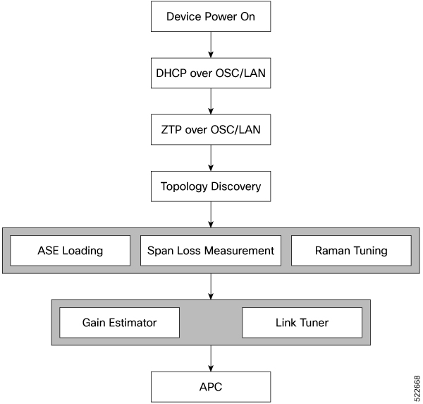
These stages describe how optical applications work during automatic link bringup.
- After you complete ZTP configuration, the NCS 1010 and NCS 1020 devices use OSPF to perform topology discovery. Each node identifies its adjacent node and learns the network topology.
- After discovering neighbor nodes, the device initiates span loss measurement.
- The device initiates Raman tuning if the span is a Raman span.
- The OLT begins ASE loading to load all the channels with noise.
-
After ASE loading, span loss measurement, and Raman tuning finish, the device begins startup gain estimation and link tuner operations.
The startup gain estimation sets the target gain and gain mode for the EDFA amplifier. The link tuner provides the target
PSDs for the channels.

Note
The startup gain estimation analyzes the span loss. It sets the gain mode of the EDFA amplifier and provides the initial target gain for the amplifier. EDFA amplifiers are present in both OLT and ILA variants of NCS 1010. These EDFA amplifiers are variable-gain optical amplifiers capable of working at two different gain ranges or modes. The modes are normal mode and extended mode. Extended mode provides higher gain than the normal mode. Changing the gain mode of an amplifier is impacting traffic. Therefore, Automatic Power Correction (APC) is unable to change the gain mode of an amplifier.
- After startup gain estimation and link tuner operations finish, the device initiates APC. APC uses the target PSDs set by the link tuner and regulates power output for all channels.
Result
The automatic link bringup process is complete. The optical link is active, and all the noise channels loaded with ASE have their target PSDs set by the link tuner.
What’s next
Create and configure optical cross-connects so that traffic runs on the link.
Enable or disable automatic link bringup
Use this task to automatically bring up the DWDM optical link without manual intervention.
Procedure
|
Use these commands to enable automatic link bringup. Example:Use the no automatic-link-bringup command to disable automatic link bringup. |
 Feedback