- Preface
- New and Changed Information
- Understanding the Carrier Packet Transport System
- Hardware
- Configuring Ethernet Virtual Circuit
- Configuring Multiprotocol Label Switching
- Configuring MPLS–Transport Profile
- Configuring Pseudowire
- Configuring Virtual Private LAN Services
- Configuring Quality of Service
- Configuring High Availability
- Configuring Resilient Ethernet Protocol
- Configuring Link Aggregation Group and Link Aggregation Control Protocol
- Configuring Span
- Configuring MAC Learning
- Configuring Multicast VLAN Registration
- Configuring IGMP Snooping
- Configuring Ethernet OAM, Connectivity Fault Management, and Y.1731
- Configuring Synchronous Ethernet
- Configuring Performance Monitoring, RMON, OTN, and Port Provisioning
- Configuring Local Authentication
- Configuring Cisco Discovery Protocol
- Alarm Troubleshooting
- SNMP
- CPT Error Messages
- Support for MSTP Cards
- Network Element Defaults
- Index
- Understanding Any Transport over MPLS
- Understanding Ethernet over MPLS
- NTP-J29 Configure Ethernet over MPLS
- DLP-J84 Configure Ethernet over MPLS in VLAN Mode Using Cisco IOS Commands
- DLP-J85 Configure Ethernet over MPLS in Port Mode Using Cisco IOS Commands
- DLP-J86 Configure Ethernet over MPLS with VLAN ID Rewrite Using Cisco IOS Commands
- DLP-J87 Configure MTU for Ethernet over MPLS Using Cisco IOS Commands
- Understanding L2VPN Pseudowire
- Supported Pseudowire Combinations
- Rewrite Operations on Pseudowire
- Static and Dynamic Multisegment Pseudowires for MPLS–TP
- NTP-J30 Create a Pseudowire Class
- DLP-J88 Create a Pseudowire Class Using Cisco IOS Commands
- DLP-J89 Create a Pseudowire Class Using CTC
- NTP-J31 Configure a Pseudowire
- DLP-J90 Create a Pseudowire Using Cisco IOS Commands
- DLP-J92 Configure L2VPN Multisegment Pseudowires Using Cisco IOS Commands
- DLP-J227 Configure Static-to-Static Multisegment Pseudowires for MPLS-TP Using Cisco IOS Commands
- DLP-J228 Configure Static-to-Dynamic Multisegment Pseudowires for MPLS-TP Using Cisco IOS Commands
- DLP-J91 Create a Pseudowire Using CTC
- DLP-J223 Edit a Pseudowire Using CTC
- DLP-J93 Perform ping mpls and trace mpls Operations on L2VPN Multisegment Pseudowires Using Cisco IOS Commands
- DLP-J94 Configure L2VPN Pseudowire Preferential Forwarding Using Cisco IOS Commands
- Understanding L2VPN Pseudowire Redundancy
- Understanding MPLS Pseudowire Status Signaling
- Understanding L2VPN Pseudowire Stitching
- Understanding Remote Ethernet Port Shutdown
- Understanding BFD Control Channel over VCCV
Configuring Pseudowire
This chapter describes static and dynamic pseudowires. This chapter also describes the configuration procedures of pseudowires.
- Understanding Any Transport over MPLS
- Understanding Ethernet over MPLS
- Understanding L2VPN Pseudowire
- Understanding L2VPN Pseudowire Redundancy
- Understanding MPLS Pseudowire Status Signaling
- Understanding L2VPN Pseudowire Stitching
- Understanding Remote Ethernet Port Shutdown
- Understanding BFD Control Channel over VCCV
Understanding Any Transport over MPLS
Any Transport over MPLS (AToM) feature provides the following capabilities:
Transport data link layer (Layer 2) packets over an MPLS backbone.
Enable service providers to connect customer sites with existing Layer 2 networks by using a single, integrated, packet–based network infrastructure — an MPLS network. Instead of using separate networks with network management environments, service providers can deliver Layer 2 connections over an MPLS backbone.
Provide a common framework to encapsulate and transport supported Layer 2 traffic types over an MPLS network core.
 Note | CPT supports only Ethernet over MPLS as the transport type under AToM in this release. |
Prerequisites
Before configuring AToM, ensure that the network is configured as follows:
Configure IP routing in the core so that the provider edge (PE) routers can reach each other via IP.
Configure MPLS in the core so that a Label Switched Path (LSP) exists between the PE routers.
Enable Cisco Express Forwarding or distributed Cisco Express Forwarding before configuring any Layer 2 circuits.
Configure a loopback interface for originating and terminating Layer 2 traffic. Ensure that the PE routers can access the loopback interface of the other router.
Restrictions
The following restrictions pertain to Ethernet over MPLS feature under AToM:
Configure the Label Distribution Protocol (LDP) router ID on all the PE routers to be a loopback address with a /32 mask. Otherwise, some configurations might not function properly.
Ethernet over MPLS supports VLAN packets that conform to the IEEE 802.1Q standard. The 802.1Q specification establishes a standard method for inserting VLAN membership information into Ethernet frames. The Inter–Switch Link (ISL) protocol is not supported between the PE and CE routers.
The AToM control word is supported. However, if the peer PE does not support a control word, the control word is disabled. This negotiation is done by LDP label binding.
Ethernet packets with hardware–level cyclic redundancy check (CRC) errors, framing errors, and runt packets are discarded on input.
Benefits
The following list explains some of the benefits of enabling Layer 2 packets to be sent in the MPLS network:
AToM adheres to the standards developed for transporting Layer 2 packets over MPLS. This benefits the service provider that wants to incorporate industry–standard methodologies in the network. Other Layer 2 solutions are proprietary, which can limit the ability of the service provider to expand the network and can force the service provider to use the equipment of only one vendor.
Upgrading to AToM is transparent to the customer. Because the service provider network is separate from the customer network, the service provider can upgrade to AToM without disruption of service to the customer. The customers assume that they are using a traditional Layer 2 backbone.
How AToM Transports Layer 2 Packets
AToM encapsulates Layer 2 frames at the ingress PE and sends them to a corresponding PE at the other end of a pseudowire, which is a connection between the two PE routers. The egress PE removes the encapsulation and sends out the Layer 2 frame.
The successful transmission of the Layer 2 frames between PE routers is due to the configuration of the PE routers. Set up the connection, called a pseudowire, between the routers. Pseudowire is the emulation of services over the MPLS network.
Specify the following information on each PE router:
The type of Layer 2 data that is transported across the pseudowire, such as Ethernet.
The IP address of the loopback interface of the peer PE router, which enables the PE routers to communicate.
A unique combination of peer PE IP address and Virtual Circuit ID (VC ID) that identifies the pseudowire.
Understanding Ethernet over MPLS
You can configure Ethernet over MPLS in the following modes:
Ethernet over MPLS in VLAN mode
Ethernet over MPLS in Port mode
Ethernet over MPLS in VLAN ID Rewrite mode
Ethernet over MPLS in VLAN Mode
A VLAN is a switched network that is logically segmented by functions, project teams, or applications regardless of the physical location of users. Ethernet over MPLS allows you to connect two VLAN networks that are in different locations. You can configure the PE routers at each end of the MPLS backbone and add a point-to-point VC. Only the two PE routers at the ingress and egress points of the MPLS backbone are aware of the VCs dedicated to transporting Layer 2 VLAN traffic. All other routers do not have table entries for those VCs. Ethernet over MPLS in VLAN mode transports Ethernet traffic from a source 802.1Q VLAN to a destination 802.1Q VLAN over a core MPLS network.
Note | You must configure Ethernet over MPLS (VLAN mode) on the Ethernet Flow Points (EFPs). |
Ethernet over MPLS in Port Mode
Port mode allows a frame coming into an interface to be packed into an MPLS packet and transported over the MPLS backbone to an egress interface. The entire Ethernet frame is transported as a single packet. You can configure port mode xconnect by using EFP mode with encapsulation default. You can then specify the destination address and the VC ID. Each interface is associated with one unique pseudowire VC label.
When configuring Ethernet over MPLS in port mode, use the following guidelines:
Ethernet over MPLS in VLAN ID Rewrite Mode
The VLAN ID rewrite mode enables you to use VLAN interfaces with different VLAN IDs at both ends of the tunnel.
- NTP-J29 Configure Ethernet over MPLS
- DLP-J84 Configure Ethernet over MPLS in VLAN Mode Using Cisco IOS Commands
- DLP-J85 Configure Ethernet over MPLS in Port Mode Using Cisco IOS Commands
- DLP-J86 Configure Ethernet over MPLS with VLAN ID Rewrite Using Cisco IOS Commands
- DLP-J87 Configure MTU for Ethernet over MPLS Using Cisco IOS Commands
NTP-J29 Configure Ethernet over MPLS
| Purpose | This procedure configures Ethernet over MPLS using Cisco IOS commands. |
| Tools/Equipment | None |
| Prerequisite Procedures | None |
| Required/As Needed | As needed |
| Onsite/Remote | Onsite or remote |
| Security Level | Provisioning or higher |
Stop. You have completed this procedure. |
DLP-J84 Configure Ethernet over MPLS in VLAN Mode Using Cisco IOS Commands
| Purpose | This procedure configures Ethernet over MPLS in VLAN mode using Cisco IOS commands. |
| Tools/Equipment | None |
| Prerequisite Procedures | None |
| Required/As Needed | As needed |
| Onsite/Remote | Onsite |
| Security Level | Provisioning or higher |
Note | You must configure Ethernet over MPLS in VLAN mode on the EFPs. |
DLP-J85 Configure Ethernet over MPLS in Port Mode Using Cisco IOS Commands
| Purpose | This procedure configures Ethernet over MPLS in port mode using Cisco IOS commands. |
| Tools/Equipment | None |
| Prerequisite Procedures | None |
| Required/As Needed | As needed |
| Onsite/Remote | Onsite |
| Security Level | Provisioning or higher |
DLP-J86 Configure Ethernet over MPLS with VLAN ID Rewrite Using Cisco IOS Commands
| Purpose | This procedure configures Ethernet over MPLS with VLAN ID rewrite using Cisco IOS commands. |
| Tools/Equipment | None |
| Prerequisite Procedures | None |
| Required/As Needed | As needed |
| Onsite/Remote | Onsite |
| Security Level | Provisioning or higher |
The VLAN ID rewrite feature enables you to use VLAN interfaces with different VLAN IDs at both ends of the tunnel.
Example: Configure Ethernet over MPLS with VLAN ID Rewrite
The following example shows how to configure VLAN ID rewrite on peer PE routers.
PE1:
interface TenGigabitEthernet4/1
encapsulation dot1Q 2
no ip directed-broadcast
no cdp enable
rewrite ingress tag push dot1q 20
xconnect 10.5.5.5 2 encapsulation mpls
PE2:
interface TenGigabitEthernet4/2
encapsulation dot1Q 3
no ip directed-broadcast
no cdp enable
rewrite ingress tag push dot1q 30
xconnect 10.3.3.3 2 encapsulation mpls
DLP-J87 Configure MTU for Ethernet over MPLS Using Cisco IOS Commands
| Purpose | This procedure configures MTU for Ethernet over MPLS using Cisco IOS commands. |
| Tools/Equipment | None |
| Prerequisite Procedures | None |
| Required/As Needed | As needed |
| Onsite/Remote | Onsite |
| Security Level | Provisioning or higher |
Understanding L2VPN Pseudowire
supports the forwarding of the Ethernet frames coming from the customer networks under AToM. The technique used to transport such a frame is called a pseudowire that is the emulation of a native service over the MPLS network.
Note | You can create static and dynamic pseudowires. The static pseudowire can carry traffic over LDP, MPLS-TE tunnels, and MPLS-TP tunnels. The dynamic pseudowire can carry traffic over LDP and MPLS–TE tunnels. |
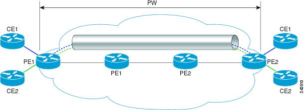
An L2VPN pseudowire is a tunnel established between the two PE routers across the core carrying the Layer 2 payload encapsulated as MPLS data, as shown in Figure 1. This helps the carriers migrate from Layer 2 networks such as Ethernet over MPLS to an MPLS core. In the L2VPN pseudowire shown in Figure 2, the pseudowires between the two PE routers are located within the same autonomous system. The routers PE1 and PE2 are called terminating PE routers (T-PEs). The attachment circuits (AC) are bound to the pseudowire on these PE routers.
Dual homed pseudowire is a pseudowire protected circuit where the destination point is split on two different nodes. In Dual home pseudowire protection, the active AC port is up and the protect AC port is down. When the active AC port goes down, the protect AC port comes up.
Understanding L2VPN Multisegment Pseudowire
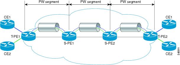
An L2VPN multisegment pseudowire is a set of two or more pseudowire segments that function as a single pseudowire. It is also known as stitched pseudowire. The multisegment pseudowires span multiple cores or autonomous systems of the same or different carrier networks. An L2VPN multisegment pseudowire can include up to 254 pseudowire segments.
The end routers are called terminating PE routers (T-PEs), and the switching routers are called S-PE routers. The S-PE router terminates the tunnels of the preceding and succeeding pseudowire segments in a multisegment pseudowire. The S-PE router can switch the control and data planes of the preceding and succeeding pseudowire segments of the multisegment pseudowire. A multisegment pseudowire is declared to be up when all the single-segment pseudowires are up.
You can create both static segments and dynamic segments for a multisegment pseudowire. When you enable the control word on one segment, ensure that the control word is enabled on the other segments as well.
See Static and Dynamic Multisegment Pseudowires for MPLS–TP for information on multisegment pseudowires for MPLS–TP.
Restrictions for L2VPN Multisegment Pseudowires
- Supported Pseudowire Combinations
- Rewrite Operations on Pseudowire
- Static and Dynamic Multisegment Pseudowires for MPLS–TP
- NTP-J30 Create a Pseudowire Class
- DLP-J88 Create a Pseudowire Class Using Cisco IOS Commands
- DLP-J89 Create a Pseudowire Class Using CTC
- NTP-J31 Configure a Pseudowire
- DLP-J90 Create a Pseudowire Using Cisco IOS Commands
- DLP-J92 Configure L2VPN Multisegment Pseudowires Using Cisco IOS Commands
- DLP-J227 Configure Static-to-Static Multisegment Pseudowires for MPLS-TP Using Cisco IOS Commands
- DLP-J228 Configure Static-to-Dynamic Multisegment Pseudowires for MPLS-TP Using Cisco IOS Commands
- DLP-J91 Create a Pseudowire Using CTC
- DLP-J223 Edit a Pseudowire Using CTC
- DLP-J93 Perform ping mpls and trace mpls Operations on L2VPN Multisegment Pseudowires Using Cisco IOS Commands
- DLP-J94 Configure L2VPN Pseudowire Preferential Forwarding Using Cisco IOS Commands
Supported Pseudowire Combinations
The following table lists the types of tunnels that are supported for static and dynamic single segment pseudowires.
| Pseudowire Type | LDP | MPLS-TE Tunnel | MPLS-TP Tunnel with IP Address | MPLS-TP Tunnel without IP Address |
|---|---|---|---|---|
| Static | Yes | Yes | Yes | Yes |
| Dynamic | Yes | Yes | No | No |
The following table lists the OAM protocols supported for static and dynamic single segment pseudowires.
| Pseudowire Type | Targeted LDP | Static OAM | BFD over VCCV | BFD over VCCV with AC Status Signaling |
|---|---|---|---|---|
| Static pseudowire over MPLS-TP | No | Yes | Yes | Yes |
| Static pseudowire over LDP | No | Yes | Yes | Yes |
| Static pseudowire over MPLS-TE | No | Yes | Yes | Yes |
| Dynamic pseudowire over LDP | Yes | No | Yes | No |
| Dynamic pseudowire over MPLS-TE | Yes | No | Yes | No |
The following table lists the OAM protocols supported for static and dynamic multisegment pseudowires.
| Pseudowire Type | Targeted LDP | Static OAM | BFD over VCCV | BFD over VCCV with AC Status Signaling |
|---|---|---|---|---|
| Static-Static | No | Yes | Yes | Yes |
| Static-Dynamic | Yes | Yes | Yes | Yes |
| Dynamic-Dynamic | Yes | Not applicable | Yes | Not applicable |
Rewrite Operations on Pseudowire
The following tables list the rewrite operations supported on pseudowire.
| EFP Encapsulation | Incoming Encapsulation Type | Ingress Rewrite Operation | Outgoing Encapsulation Type | Pseudowire Type |
|---|---|---|---|---|
| encapsulation dot1q vlan id | 0x8100 | 0x8100 | Ethernet and VLAN | |
| encapsulation dot1q vlan id | 0x8100 | 0x8100 | Ethernet | |
| encapsulation dot1q vlan id | 0x8100 | Not applicable | Ethernet and VLAN | |
| encapsulation dot1q vlan id | 0x8100 | any | Ethernet and VLAN | |
| encapsulation dot1q vlan id | 0x8100 | any | Ethernet | |
| encapsulation dot1q vlan id | 0x8100 | any | Ethernet | |
| encapsulation dot1q any | 0x8100 | Not applicable | Ethernet and VLAN | |
| encapsulation dot1q any | 0x8100 | 0x8100 | Ethernet and VLAN | |
| encapsulation dot1q any | 0x8100 | Not applicable | Ethernet | |
| encapsulation untagged | 0x8100 | 0x8100 | Ethernet and VLAN | |
| encapsulation untagged | 0x8100 | 0x8100 | Ethernet | |
| encapsulation default | Not applicable | Not applicable | Ethernet and VLAN | |
| encapsulation default | Not applicable | 0x8100 | Ethernet and VLAN | |
| encapsulation default | Not applicable | 0x8100 | Ethernet | |
| encapsulation double tagged | 0x8100 and second 0x8100 | 0x8100 | Ethernet and VLAN | |
| encapsulation double tagged | 0x8100 and second 0x8100 | 0x8100 and second 0x8100 | Ethernet and VLAN | |
| encapsulation double tagged | 0x8100 and second 0x8100 | 0x8100 | Ethernet | |
| encapsulation double tagged | 0x8100 and second 0x8100 | any | Ethernet | |
| encapsulation double tagged | 0x8100 and second 0x8100 | 0x8100 | Ethernet and VLAN | |
| encapsulation double tagged | 0x8100 and second 0x8100 | 0x8100 and second 0x8100 | Ethernet | |
| encapsulation double tagged | 0x88a8 and second 0x8100 | 0x8100 and second 0x8100 | Ethernet | |
| encapsulation double tagged | 0x8100 and second 0x8100 | 0x88a8 and second 0x8100 | Ethernet | |
| encapsulation single tagged | 0x8100 | 0x8100 and second 0x8100 | Ethernet | |
| encapsulation untagged | untagged | 0x88a8 and 0x8100 | Ethernet | |
| encapsulation untagged | untagged | 0x8100 and second 0x8100 | Ethernet | |
| encapsulation single tagged | 0x8100 | 0x8100 and second 0x8100 | Ethernet and VLAN | |
| encapsulation double tagged | 0x8100 and second 0x8100 | 0x8100 and second 0x8100 | Ethernet and VLAN | |
| encapsulation single tagged | 0x88a8 | 0x8100 and second 0x8100 | Ethernet | |
| encapsulation double tagged | 0x8100 and second 0x8100 | 0x8100 | Ethernet | |
| encapsulation double tagged | 0x88a8 and 0x8100 | 0x88a8 | Ethernet | |
| encapsulation double tagged | 0x8100 and second 0x8100 | untagged | Ethernet | |
| encapsulation double tagged | 0x88a8 and 0x8100 | untagged | Ethernet | |
| encapsulation single tagged | 0x8100 | untagged | Ethernet and VLAN | |
| encapsulation dot1q range | 0x8100 | Not applicable | Ethernet and VLAN | |
| encapsulation dot1q range | 0x8100 | 0x8100 | VLAN | |
| encapsulation dot1q range | 0x8100 | 0x8100 | Ethernet | |
| encapsulation dot1ad any/range | 0x8100 | 0x8100 | Ethernet and VLAN | |
| encapsulation dot1ad any/range | 0x8100 | any | Ethernet |
Static and Dynamic Multisegment Pseudowires for MPLS–TP
MPLS-TP supports the following combinations of static and dynamic multisegment pseudowires:
MPLS–TP: Pseudowire Redundancy for Static and Dynamic Multisegment Pseudowires
MPLS-TP supports pseudowire redundancy for the following combinations of static and dynamic pseudowires:
MPLS–TP: OAM Status for Static and Dynamic Multisegment Pseudowires
With static pseudowires, status notifications can be provided by BFD over VCCV or static pseudowire OAM protocol. However, BFD over VCCV sends only attachment circuit status code notifications. Hop-by-hop notifications of other pseudowire status codes are not supported. Therefore, static pseudowire OAM protocol is preferred. You can acquire per pseudowire OAM for attachment circuit/pseudowire notification over VCCV channel with or without the control word.
NTP-J30 Create a Pseudowire Class
| Purpose | This procedure creates a pseudowire class. |
| Tools/Equipment | None |
| Prerequisite Procedures | None |
| Required/As Needed | As needed |
| Onsite/Remote | Onsite or remote |
| Security Level | Provisioning or higher |
Stop. You have completed this procedure. |
DLP-J88 Create a Pseudowire Class Using Cisco IOS Commands
| Purpose |
This procedure creates a pseudowire class using Cisco IOS commands. |
| Tools/Equipment | None |
| Prerequisite Procedures | |
| Required/As Needed | As needed |
| Onsite/Remote | Onsite or remote |
| Security Level | Provisioning or higher |
When you create the pseudowire class, you specify the parameters of the pseudowire, such as the use of control word, preferred path, OAM class, and VCCV BFD template.
Note | To create a pseudowire for TDM SFP, pseudowire class should not has control-word, sequencing, OAM, BFDoVCC, Dynamic tunnel and Dynamic Protocol attributes. |
Example: Create a Pseudowire Class
The following example creates a pseudowire class using Cisco IOS commands:
Router> enable
Router# configure terminal
Router(config)# pseudowire-class class1
Router(config-pw-class)# encapsulation mpls
Router(config-pw-class)# control-word
Router(config-pw-class)# protocol ldp
Router(config-pw-class)# preferred-path interface tunnel 1 disable-fallback
Router(config-pw-class)# status protocol notification static oam-class1
Router(config-pw-class)# vccv bfd template bfdtemplate1 raw-bfd
Router(config-pw-class)# exit
DLP-J89 Create a Pseudowire Class Using CTC
| Purpose |
This procedure creates a pseudowire class using CTC. |
| Tools/Equipment | None |
| Prerequisite Procedures | |
| Required/As Needed | As needed |
| Onsite/Remote | Onsite or remote |
| Security Level | Provisioning or higher |
Note | You can also create a pseudowire class automatically. Refer to the DLP-J107 Create an MPLS–TP Tunnel Using CTC procedure. |
Note | To create a pseudowire for TDM SFP, pseudowire class should not has control-word, sequencing, OAM, BFDoVCC, Dynamic tunnel and Dynamic Protocol attributes. |
| Step 1 | Complete the NTP-J22 Log into CTC procedure at a node where you want to create a pseudowire class. | ||||
| Step 2 | From the View menu, choose Go to Home View. | ||||
| Step 3 | Right-click the fabric or line card and choose Open Packet Transport System View. The Packet Transport System View dialog box appears. | ||||
| Step 4 | Click the Provisioning tab. | ||||
| Step 5 | From the left pane, click Pseudowire Class. | ||||
| Step 6 | Click Create. The Create Pseudowire Class dialog box appears. | ||||
| Step 7 | Enter the name of the pseudowire class in the Name field. The encapsulation type for tunneling Layer 2 traffic over a pseudowire is set to MPLS and cannot be changed. | ||||
| Step 8 | From the
Interworking drop-down list, choose
VLAN or
Ethernet.
The
Interworking option enables the translation between the different Layer 2
encapsulations.
| ||||
| Step 9 | If unchecked, check the Control Word check box to enable the control word in a dynamic pseudowire connection. | ||||
| Step 10 | Check the Master Redundancy check box to place the pseudowire redundancy group on this node in master mode. | ||||
| Step 11 | In the Preferred
Path area, specify the MPLS–TP or MPLS–TE tunnel path that must be used by the
pseudowire.
| ||||
| Step 12 | In the Protocol
area, choose
LDP or
NONE to
specify the signaling protocol to be used to manage the pseudowires created
from this pseudowire class.
| ||||
| Step 13 | In the
Sequencing area, specify the direction in which the sequencing of packets in a
pseudowire is enabled.
| ||||
| Step 14 | In the BFDoVCCV area, enable BFD over VCCV for a pseudowire class. | ||||
| Step 15 | In the Status OAM area: | ||||
| Step 16 | Click OK to create a pseudowire class. | ||||
| Step 17 | Return to your originating procedure (NTP). |
NTP-J31 Configure a Pseudowire
| Purpose | This procedure configures a pseudowire. |
| Tools/Equipment | None |
| Prerequisite Procedures | None |
| Required/As Needed | As needed |
| Onsite/Remote | Onsite or remote |
| Security Level | Provisioning or higher |
Stop. You have completed this procedure. |
DLP-J90 Create a Pseudowire Using Cisco IOS Commands
| Purpose |
This procedure creates a static and dynamic pseudowire using Cisco IOS commands. |
| Tools/Equipment | None |
| Prerequisite Procedures | |
| Required/As Needed | As needed |
| Onsite/Remote | Onsite or remote |
| Security Level | Provisioning or higher |
The successful transmission of the Layer 2 frames between the provider edge routers is due to the configuration of the PE routers. You set up the connection, called a pseudowire, between the routers.
Note | Do not set labels to create a dynamic pseudowire. |
Note | If a VPWS is provisioned between two nodes where one node is running CPT version 9.7.0.2 and the other node is running older version. Before provisioning the pseudowire, edit the TDM SFP labels to the default values. |
| Command or Action | Purpose | |||
|---|---|---|---|---|
| Step 1 | enable
Example:Router> enable |
Enables privileged EXEC mode. | ||
| Step 2 | configure terminal
Example:Router# configure terminal |
Enters global configuration mode. | ||
| Step 3 | interface
type
number
Example:Router(config)# interface TenGigabitEthernet4/1 |
Specifies the interface to configure and enters interface configuration mode. | ||
| Step 4 | xconnect
peer-ip-address
vcid
encapsulation mpls
pw-class
pw-class-name
[sequencing {transmit |
receive |
both}]
Example:Router(config-if)# xconnect 10.131.191.252 100 encapsulation mpls pw-class class1 | Binds an attachment circuit to a pseudowire and configures a static pseudowire. | ||
| Step 5 | mpls label
local-pseudowire-label
remote-pseudowire-label
Example:Router(config-if-xconn)# mpls label 100 150 | Sets the
local and remote labels for the static pseudowire. Do not set labels to create
a dynamic pseudowire.
| ||
| Step 6 | mpls control-word
Example:Router(config-if-xconn)# no mpls control-word |
Enables the MPLS control word. If you enable inclusion of the control word, it must be enabled on both ends of the connection for the circuit to work properly. | ||
| Step 7 | exit
Example:Router(config-if-xconn)# exit |
Returns the router to interface configuration mode. | ||
| Step 8 | exit
Example:Router(config-if)# exit |
Returns the router to global configuration mode.
| ||
| Step 9 | Return to your originating procedure (NTP). |
— |
Example: Create a Pseudowire
The following example creates a static pseudowire using Cisco IOS commands:
Router> enable
Router# configure terminal
Router(config)# interface TenGigabitEthernet4/1
Router(config-if)# xconnect 10.131.191.251 100 encapsulation mpls pw-class class1
Router(config-if-xconn)# mpls label 100 150
Router(config-if-xconn)# no mpls control-word
Router(config-if-xconn)# exit
Router(config-if)# exit
DLP-J92 Configure L2VPN Multisegment Pseudowires Using Cisco IOS Commands
| Purpose | This procedure configures L2VPN multisegment pseudowires using Cisco IOS commands. |
| Tools/Equipment | None |
| Prerequisite Procedures | |
| Required/As Needed | As needed |
| Onsite/Remote | Onsite |
| Security Level | Provisioning or higher |
| Command or Action | Purpose | |||
|---|---|---|---|---|
| Step 1 | enable Example:Router> enable | Enables privileged EXEC mode. | ||
| Step 2 | configure terminal Example:Router# configure terminal | Enters global configuration mode. | ||
| Step 3 | mpls label protocol ldp Example: Router(config)# mpls label protocol ldp | Configures the use of LDP on all the interfaces. | ||
| Step 4 | mpls ldp router-id interface force Example: Router(config)# mpls ldp router-id loopback0 force | Specifies the preferred interface for determining the LDP router ID. | ||
| Step 5 | pseudowire-class name Example: Router(config)# pseudowire-class atom | Establishes a pseudowire class with a name that you specify, and enters pseudowire class configuration mode. Ensure that the interworking and control word are the same. | ||
| Step 6 | encapsulation mpls Example:Router(config-pw-class)# encapsulation mpls | Specifies the tunneling encapsulation. For MPLS L2VPNs, the encapsulation type is mpls. | ||
| Step 7 | switching tlv Example:Router(config-pw-class)# switching tlv | (Optional) Enables the advertisement of the switching point type, length, value (TLV) in label binding. This command is enabled by default. | ||
| Step 8 | exit Example:Router(config-pw-class)# exit | Exits pseudowire class configuration mode. | ||
| Step 9 | l2 vfi name point-to-point Example:Router(config)# l2 vfi atomtunnel point-to-point | Creates a point-to-point Layer 2 virtual forwarding interface (VFI) and enters VFI configuration mode. | ||
| Step 10 | description string Example:Router(config-vfi)# description segment1 | Provides a description of the switching PE router for a multisegment pseudowire. | ||
| Step 11 | neighbor ip-address vcid {encapsulation mpls | pw-class pw-class-name} Example:Router(config-vfi)# neighbor 10.0.0.1 100 pw-class mpls | Sets up an emulated VC. Specify the IP address and the VC ID of the peer router. Also, specify the pseudowire class to use for the emulated VC.
| ||
| Step 12 | exit Example:Router(config-vfi)# exit | Returns to global configuration mode. | ||
| Step 13 | Return to your originating procedure (NTP). | — |
DLP-J227 Configure Static-to-Static Multisegment Pseudowires for MPLS-TP Using Cisco IOS Commands
| Purpose | This procedure configures static-to-static multisegment pseudowires for MPLS–TP using Cisco IOS commands. |
| Tools/Equipment | None |
| Prerequisite Procedures | None |
| Required/As Needed | As needed |
| Onsite/Remote | Onsite or remote |
| Security Level | Provisioning or higher |
| Command or Action | Purpose | |||
|---|---|---|---|---|
| Step 1 | enable Example:Router> enable | Enables privileged EXEC mode. | ||
| Step 2 | configure terminal Example:Router# configure terminal | Enters global configuration mode. | ||
| Step 3 | l2 vfi name point-to-point Example: Router(config)# l2 vfi atomtunnel point-to-point | Creates a point-to-point Layer 2 virtual forwarding interface (VFI) and enters VFI configuration mode. | ||
| Step 4 | neighbor ip-address vc-id {encapsulation mpls | pw-class pw-class-name} Example: Router(config-vfi)# neighbor 10.0.0.1 100 pw-class mpls | Sets up an emulated VC. Specify the IP address and the VC ID of the peer router. Also, specify the pseudowire class to use for the emulated VC. | ||
| Step 5 | mpls label local-pseudowire-label remote-pseudowire-label Example:Router(config-vfi-neighbor)# mpls label 100 150 | Sets the local and remote labels for a static pseudowire. | ||
| Step 6 | mpls control-word Example:Router(config-vfi-neighbor)# mpls control-word | Enables the MPLS control word.
| ||
| Step 7 | exit Example:Router(config-vfi-neighbor)# exit | Exits VFI neighbor configuration mode. | ||
| Step 8 | Return to your originating procedure (NTP). Example:— |
DLP-J228 Configure Static-to-Dynamic Multisegment Pseudowires for MPLS-TP Using Cisco IOS Commands
| Purpose | This procedure configures static-to-dynamic multisegment pseudowires for MPLS–TP using Cisco IOS commands. |
| Tools/Equipment | None |
| Prerequisite Procedures | None |
| Required/As Needed | As needed |
| Onsite/Remote | Onsite or remote |
| Security Level | Provisioning or higher |
Note | When you configure static-to-dynamic pseudowires, you configure the static pseudowire class with the protocol none command. |
| Command or Action | Purpose | |
|---|---|---|
| Step 1 | Configure the static pseudowire. Example: | Configures the static pseudowire. |
| Step 2 | Configure the dynamic pseudowire. Example: | Configures the dynamic pseudowire. |
| Step 3 | enable Example:Router> enable | Enables privileged EXEC mode. Perform the following steps to configure the static-to-dynamic multisegment pseudowire. |
| Step 4 | configure terminal Example:Router# configure terminal | Enters global configuration mode. |
| Step 5 | l2 vfi name point-to-point Example: Router(config)# l2 vfi atomtunnel point-to-point | Creates a point-to-point Layer 2 virtual forwarding interface (VFI) and enters VFI configuration mode. |
| Step 6 | neighbor ip-address vc-id {encapsulation mpls | pw-class pw-class-name} Example: Router(config-vfi)# neighbor 10.0.0.1 100 pw-class mpls | Sets up an emulated VC. Specify the IP address and the VC ID of the peer router. Also, specify the pseudowire class to use for the emulated VC. |
| Step 7 | mpls label local-pseudowire-label remote-pseudowire-label Example:Router(config-vfi-neighbor)# mpls label 100 150 | Sets the local and remote labels for a static pseudowire. |
| Step 8 | mpls control-word Example:Router(config-vfi-neighbor)# mpls control-word | Enables the MPLS control word. |
| Step 9 | local interface pseudowire-type Example:Router(config-vfi-neighbor)# local interface 5 | Specifies the pseudowire type when configuring static to dynamic pseudowires. |
| Step 10 | tlv template template-name Example:Router(config-vfi-neighbor-interface)# tlv template net | Specifies a TLV template to use as part of the local interface configuration. |
| Step 11 | exit Example:Router(config-vfi-neighbor-interface)# exit | Exits VFI neighbor interface configuration mode. |
| Step 12 | Return to your originating procedure (NTP). |
Example: Configure Static-to-Dynamic Multisegment Pseudowires for MPLS-TP
The following example shows how to configure a TLV template:
Router(config)#pseudowire-tlv template tlv-template-name
Router(config-pw-tlv-template)#tlv mtu-value 1 4 dec 1500
Router(config-pw-tlv-template)#tlv vccv-flags C 4 hexstr 0108
Router(config-pw-tlv-template)#exit
The following example shows how to configure VFI at an SPE node:
Router(config)#l2 vfi vfi::1 point-to-point
Router(config-vfi)#neighbor 3.3.3.3 1 pw-class PW_LDP_VPWS
Router(config-vfi)#neighbor 1.1.1.1 1 pw-class PW_TP_1_VPWS
Router(config-vfi-neighbor)#mpls label 17 17
Router(config-vfi-neighbor)#local interface 5
Router(config-vfi-neighbor-interface)#tlv template tlv-template-name
Router(config-vfi-neighbor-interface)#exit
Router(config-vfi-neighbor)#exit
DLP-J91 Create a Pseudowire Using CTC
| Purpose |
This procedure allows you to do the following: |
| Tools/Equipment | None |
| Prerequisite Procedures | |
| Required/As Needed | As needed |
| Onsite/Remote | Onsite or remote |
| Security Level | Provisioning or higher |
The pseudowire configuration can be EVC VLAN–based or EVC port–based. CPT supports only Ethernet over MPLS as the transport type for pseudowire.
| Step 1 | Complete the NTP-J22 Log into CTC procedure at a node where you want to create a pseudowire. | ||||
| Step 2 | From the View menu, choose Go to Network View. | ||||
| Step 3 | Click the Layer2+ tab. | ||||
| Step 4 | From the left pane, click Circuits. | ||||
| Step 5 | Click the Pseudowire tab. | ||||
| Step 6 | Click Create. The Circuit Creation wizard appears. | ||||
| Step 7 | In the AC Global
Attributes area of the Circuit Attributes screen, specify the global attributes
as follows:
| ||||
| Step 8 | In the Redundancy
area of the Circuit Attributes screen, specify the following to create a
redundant pseudowire:
| ||||
| Step 9 | To choose a non
CPT source
node for the pseudowire, complete the following steps:
| ||||
| Step 10 | To choose a
CPT source
node for the pseudowire, choose the
CPT node
from the Node drop-down list. The Router ID field is automatically populated.
| ||||
| Step 11 | In the AC End
Point area of the T-PE1 screen, identify the attachment circuit (AC) with the
exact end point of the
CPT node
as follows:
The attachment circuit is the physical or virtual circuit attaching a CE to a PE. | ||||
| Step 12 | In the AC
Attributes area of the T-PE1 screen, specify the following:
| ||||
| Step 13 | In the PW
Attributes area of the T-PE1 screen, specify the following:
| ||||
| Step 14 | In the Backup PW
Attributes area of the T-PE1 screen, specify the following:
| ||||
| Step 15 | From the Node
drop-down list, choose the destination node for the pseudowire.
You can choose a CPT or non CPT node as the destination node similar to the source node. | ||||
| Step 16 | Specify all the values in the T-PE2 screen similar to the previous T-PE1 screen. | ||||
| Step 17 | If you had checked the Dual Homed Peer check box in the Circuit Attributes screen, an additional screen appears to specify the settings for T-PE3. | ||||
| Step 18 | Click
Next.
The PW Protected Circuit Path screen appears. | ||||
| Step 19 | In the PW
Protected Circuit Path screen, specify the following for Switch Provider Edge
(SPE) nodes to create a multisegment pseudowire.
| ||||
| Step 20 | Click the SPEs Backup tab and specify all the values similar to the SPEs Working tab. | ||||
| Step 21 | Click
Finish to create a pseudowire.
| ||||
| Step 22 | Return to your originating procedure (NTP). |
DLP-J223 Edit a Pseudowire Using CTC
| Purpose |
This procedure edits a pseudowire using CTC. |
| Tools/Equipment | None |
| Prerequisite Procedures | |
| Required/As Needed | As needed |
| Onsite/Remote | Onsite or remote |
| Security Level | Provisioning or higher |
| Step 1 | Complete the NTP-J22 Log into CTC procedure at a node where you want to edit a pseudowire. | ||||
| Step 2 | From the View menu, choose Go to Home View. | ||||
| Step 3 | Click the Layer2+ tab. | ||||
| Step 4 | Click Pseudo Wire. | ||||
| Step 5 | From the list of pseudowires, select a pseudowire to edit. | ||||
| Step 6 | Click Edit. The Edit Circuit screen appears. | ||||
| Step 7 | In the General tab, modify the following attributes of the pseudowire as required and click Apply: | ||||
| Step 8 | In the T-PE Nodes tab, view the details of the terminating provider edge nodes that are the end points of this pseudowire. | ||||
| Step 9 | In the State tab, complete the following: | ||||
| Step 10 | In the QoS tab, modify the table map, ingress policy, and egress policy of the pseudowire as required and click Apply. | ||||
| Step 11 | Close the
Edit Circuit
screen.
| ||||
| Step 12 | Return to your originating procedure (NTP). |
DLP-J93 Perform ping mpls and trace mpls Operations on L2VPN Multisegment Pseudowires Using Cisco IOS Commands
| Purpose | Use the ping mpls and trace mpls commands to verify that all the segments of the MPLS multisegment pseudowire are operating. |
| Tools/Equipment | None |
| Prerequisite Procedures | None |
| Required/As Needed | As needed |
| Onsite/Remote | Onsite or remote |
| Security Level | Provisioning or higher |
You can use the ping mpls command to verify connectivity at the following pseudowire points:
From one end of the pseudowire to the other
From one of the pseudowires to a specific segment
The segment between two adjacent S-PE routers
You can use the trace mpls command to verify connectivity at the following pseudowire points:
From one end of the pseudowire to the other
From one of the pseudowires to a specific segment
The segment between two adjacent S-PE routers
A range of segments
Note | Enable l2 router-id IP address command for static pseudowire ping operation to work. It is recommended to set up the router-id to the loopback0 IP address. This IP address must be the same IP address that is used in the mpls ldp router-id LDP command. |
Note | The ping and trace operation for multisegment pseudowires that have one or more static pseudowire segments is not supported. |
| Command or Action | Purpose | |
|---|---|---|
| Step 1 | ping mpls pseudowire destination-address vc-id [segment segment-number] Example:Router# ping mpls pseudowire 10.10.10.9 220 segment 2 | Performs a ping operation. |
| Step 2 | trace mpls pseudowire destination-address vc-id segment segment-number [segment-number] Example:Router# trace mpls pseudowire 10.10.10.9 220 segment 1 | Performs a trace operation.
|
| Step 3 | Return to your originating procedure (NTP). | — |
DLP-J94 Configure L2VPN Pseudowire Preferential Forwarding Using Cisco IOS Commands
| Purpose | This procedure configures L2VPN pseudowire preferential forwarding using Cisco IOS commands. |
| Tools/Equipment | None |
| Prerequisite Procedures | None |
| Required/As Needed | As needed |
| Onsite/Remote | Onsite or remote |
| Security Level | Provisioning or higher |
| Command or Action | Purpose | |||
|---|---|---|---|---|
| Step 1 | enable Example:Router> enable | Enables privileged EXEC mode. | ||
| Step 2 | configure terminal Example:Router# configure terminal | Enters global configuration mode. | ||
| Step 3 | pseudowire-class class-name Example:Router(config)# pseudowire-class atom | Establishes a pseudowire class with a name that you specify, and enters pseudowire class configuration mode. | ||
| Step 4 | encapsulation mpls Example: Router(config-pw)# encapsulation mpls | Specifies the tunneling encapsulation. For AToM, the encapsulation type is mpls. | ||
| Step 5 | status redundancy {master | slave} Example:Router(config-pw)# status redundancy master | Specifies the pseudowire as the master or slave. This enables the L2VPN Pseudowire Preferential Forwarding feature to display the status of the active and backup pseudowires. By default, the PE router is in slave mode.
| ||
| Step 6 | interworking {ethernet | vlan} Example:Router(config-pw)# interworking vlan | (Optional) Enables the translation between the different Layer 2 encapsulations. | ||
| Step 7 | exit Example:Router(config-pw)# exit | Returns to global configuration mode. | ||
| Step 8 | Return to your originating procedure (NTP). | — |
Example: Configure L2VPN Pseudowire Preferential Forwarding
The following example shows how to configure a PE router with the L2VPN Pseudowire Preferential Forwarding feature:
mpls ldp graceful-restart
mpls ip
mpls label protocol ldp
mpls ldp router-id Loopback0 force
mpls ldp advertise-labels
!
pseudowire-class mpls
 encapsulation mpls
 status redundancy master

interface TenGigabitEthernet4/1
 service instance 1 ethernet
 encapsulation dot1q 10
  xconnect 1.1.1.1 123 encapsulation mpls
   backup peer 1.1.1.2 123
end
Understanding L2VPN Pseudowire Redundancy
The L2VPN Pseudowire Redundancy feature enables you to set up backup pseudowires.
The L2VPN Pseudowire Redundancy feature lets you configure the network to detect a failure in the network and reroute the Layer 2 (L2) service to another end point that can continue to provide the service. This feature provides the ability to recover from a failure either of the remote PE router or of the link between the PE and CE routers.
The L2VPN Pseudowire Redundancy feature enables you to configure a backup pseudowire if the primary pseudowire fails. When the primary pseudowire fails, the PE router can switch to the backup pseudowire. You can have the primary pseudowire resume operation after it comes up.
Note | The static pseudowire can be backed up by the dynamic pseudowire and vice versa. |
Prerequisites
The L2VPN Pseudowire Redundancy feature requires the following mechanisms to detect a failure in the network:
Restrictions
The primary and backup pseudowires must run the same type of transport service. The primary and backup pseudowires must be configured with AToM.
Only static, on-box provisioning is supported.
If you use L2VPN Pseudowire Redundancy with L2VPN Interworking, the interworking method must be the same for the primary and backup pseudowires.
Setting the experimental (EXP) bit on the MPLS pseudowire is supported.
Different pseudowire encapsulation types on the MPLS pseudowire are not supported.
The ability to have the backup pseudowire fully operational at the same time that the primary pseudowire is operational is not supported. The backup pseudowire becomes active only after the primary pseudowire fails.
The AToM VCCV feature is supported only on the active pseudowire. The AToM VCCV feature is used for fault detection, isolation, and verification at both ends of the pseudowire.
More than one backup pseudowire is not supported.
Pseudowire Redundancy
L2VPNs can provide pseudowire resiliency through their routing protocols. When connectivity between end-to-end PE routers fails, an alternative path to the directed LDP session and the user data can take over. However, there are some parts of the network where this rerouting mechanism does not protect against interruptions in service. Figure 1 shows those parts of the network that are vulnerable to an interruption in service.
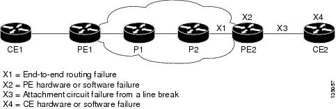
The L2VPN Pseudowire Redundancy feature provides the ability to ensure that the CE2 router in Figure 1 can always maintain network connectivity, even if one or all the failures in the figure occur.
Note | In this release, a pseudowire can be protected by only one backup pseudowire. |
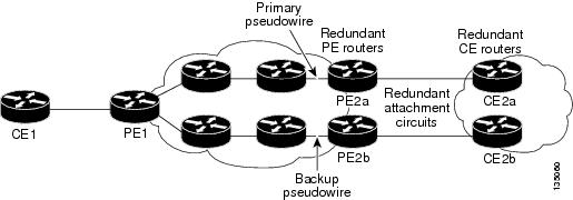
You can configure the network with redundant pseudowires and redundant network elements, which are shown in Figure 2, Figure 3, and Figure 4.
Figure 2 shows a network with redundant pseudowires and redundant attachment circuits.
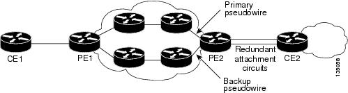
Figure 3 shows a network with redundant pseudowires, attachment circuits, and CE routers.
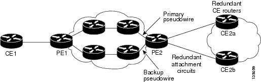
Figure 4 shows a network with redundant pseudowires, attachment circuits, CE routers, and PE routers.
NTP-J32 Configure the Pseudowire Redundancy Using Cisco IOS Commands
| Purpose | This procedure configures the L2VPN pseudowire redundancy feature using Cisco IOS commands. |
| Tools/Equipment | None |
| Prerequisite Procedures | None |
| Required/As Needed | As needed |
| Onsite/Remote | Onsite |
| Security Level | Provisioning or higher |
| Command or Action | Purpose | |
|---|---|---|
| Step 1 | enable Example:Router> enable | Enables privileged EXEC mode. |
| Step 2 | configure terminal Example:Router# configure terminal | Enters global configuration mode. |
| Step 3 | interface type number Example:Router(config)# interface TenGigabitEthernet4/1 | Specifies the interface to configure and enters interface configuration mode. |
| Step 4 | service instance serviceinstanceid ethernet Example:Router(config-if)# service instance 100 ethernet | Specifies the service instance and enters service instance configuration mode. Ensure that the EFP on the adjoining CE router is on the same VLAN as this PE router. |
| Step 5 | encapsulation dot1q vlan-id Example:Router(config-if-srv)# encapsulation dot1q 100 | Enables the EFP to accept 802.1Q VLAN packets. The EFPs between the CE and PE routers that are running Ethernet over MPLS must be in the same subnet. |
| Step 6 | xconnect peer-router-id vcid {encapsulation mpls | pw-class pw-class-name} Example:Router(config-if-srv)# xconnect 10.0.0.1 123 pw-class atom | Binds the attachment circuit to a pseudowire VC and enters xconnect configuration mode. |
| Step 7 | backup peer peer-router-ip-addr vcid [pw-class pw-class-name] Example:Router(config-if-srv-xconn)# backup peer 10.0.0.3 125 pw-class atom | Specifies a redundant peer for the pseudowire VC. The pseudowire class name must match the name you specified when you created the pseudowire class, but you can use a different pw-class in the backup peer command than the name that you used in the primary xconnect command. |
| Step 8 | backup delay enable-delay {disable-delay | never} Example:Router(config-if-srv-xconn)# backup delay 5 never | Specifies the period, in seconds, the backup pseudowire VC must wait to take over after the primary pseudowire VC goes down. The range is from 0 to 180 seconds. If you specify the never keyword, the primary pseudowire VC never takes over from the backup pseudowire VC. |
| Step 9 | exit Example:Router(config-if-srv-xconn)# exit | Returns to service instance configuration mode. |
| Step 10 | exit Example:Router(config-if-srv)# exit | Returns to global configuration mode. |
| Step 11 | Return to your originating procedure (NTP). | — |
Examples
The following example shows an Ethernet attachment circuit cross-connect with L2VPN IP interworking and a backup pseudowire:
Router> enable
Router# configure terminal
Router(config)# interface TenGigabitEthernet4/1
Router(config-if)# service instance 100 ethernet
Router(config-if-srv)# encapsulation dot1q 100
Router(config-if-srv)# xconnect 10.0.0.1 123 pw-class mpls-ip
Router(config-if-srv-xconn)# backup peer 10.0.0.3 125 pw-class mpls-ip
Understanding MPLS Pseudowire Status Signaling
The MPLS Pseudowire Status Signaling feature enables you to configure the router to send the pseudowire status to a peer router, even when the attachment circuit (AC) is down. The MPLS Pseudowire Status Signaling feature enables the AC status to be sent to the peer through LDP. The pseudowire status messages are sent in label advertisement and label notification messages if the peer router also supports the MPLS Pseudowire Status Signaling feature.
Restrictions
Both peer routers must support the ability to send and receive pseudowire status messages in label advertisement and label notification messages. If both peer routers do not support pseudowire status messages, it is recommended that you disable the messages with the no status command.
This feature is not integrated with AToM Virtual Circuit Connection Verification (VCCV).
NTP-J33 Configure MPLS Pseudowire Status Signaling Using Cisco IOS Commands
| Purpose | This procedure configures MPLS pseudowire status signaling using Cisco IOS commands. |
| Tools/Equipment | None |
| Prerequisite Procedures | None |
| Required/As Needed | As needed |
| Onsite/Remote | Onsite |
| Security Level | Provisioning or higher |
Use this procedure to enable the router to send pseudowire status to a peer router even when the attachment circuit is down. If both routers do not support pseudowire status messages, then disable the messages with the no status command.
| Command or Action | Purpose | |
|---|---|---|
| Step 1 | enable Example:Router> enable | Enables privileged EXEC mode. |
| Step 2 | configure terminal Example:Router# configure terminal | Enters global configuration mode. |
| Step 3 | pseudowire-class class-name Example:Router(config)# pseudowire-class atom | Establishes a pseudowire class with a name that you specify and enters pseudowire class configuration mode. |
| Step 4 | status Example:Router(config-pw)# status | (Optional) Enables the router to send pseudowire status messages to the peer router through label advertisement and label notification messages. By default, the status messages are enabled. This step is included only if status messages have been disabled. If both routers do not support pseudowire status messages, then disable the messages with the no status command. |
| Step 5 | encapsulation mpls Example:Router(config-pw)# encapsulation mpls | Specifies the tunneling encapsulation. |
| Step 6 | exit Example:Router(config-pw)# exit | Exits pseudowire class configuration mode. |
| Step 7 | exit Example:Router(config)# exit | Exits global configuration mode. |
| Step 8 | show mpls l2transport vc detail Example:Router# show mpls l2transport vc detail | Validates that pseudowire messages can be sent and received. |
| Step 9 | Return to your originating procedure (NTP). | — |
Example: Configure MPLS Pseudowire Status Signaling
The following example shows how to configure the MPLS Pseudowire Status Signaling feature using Cisco IOS commands:
Router> enable
Router# configure terminal
Router(config)# pseudowire-class atom
Router(config-pw)# status
Router(config-pw)# encapsulation mpls
Router(config-pw)# exit
Router(config)# exit
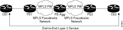
Understanding L2VPN Pseudowire Stitching
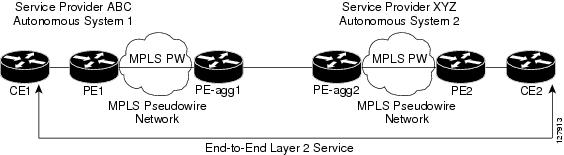
L2VPN Pseudowire Stitching defines a static or dynamically configured set of two or more pseudowire segments that behave and function as a single point-to-point pseudowire. L2VPN Pseudowire Stitching enables L2VPN pseudowires to extend across two separate MPLS networks or across an inter-AS boundary, as shown in Figure 1 and Figure 2.
L2VPN Pseudowire Stitching connects two or more contiguous pseudowire segments to form an end-to-end multihop pseudowire. This end-to-end pseudowire functions as a single point-to-point pseudowire.
As shown in Figure 2, L2VPN Pseudowire Stitching enables you to keep the IP addresses of the edge PE routers private across inter-AS boundaries. You can use the IP address of the Autonomous System Boundary Routers (ASBRs) and treat them as pseudowire aggregation (PE-agg) routers. The ASBRs join the pseudowires of the two domains.
Restrictions for L2VPN Pseudowire Stitching
L2VPN Pseudowire Stitching is supported with AToM.
Only static, on-box provisioning is supported.
Sequencing numbers in AToM packets are not processed by L2VPN Pseudowire Stitching. The feature passes the sequencing data through the cross-connect packet paths, a process that is called transparent sequencing. The end point PE to CE connections enforce the sequencing.
You can ping the adjacent next-hop PE router. End-to-end LSP pings are not supported.
Do not configure IP or Ethernet interworking on a router where L2VPN Pseudowire Stitching is enabled. Instead, configure interworking on the routers at the edge PEs of the network.
The control word negotiation results must match. If either segment does not negotiate the control word, the control word is disabled for both segments.
AToM Graceful Restart is negotiated independently on each pseudowire segment. If there is a transient loss of the LDP session between two AToM PE routers, packets continue to flow.
Per-pseudowire QoS is not supported. The TE tunnel selection is supported.
Attachment circuit interworking is not supported.
NTP-J34 Configure the Pseudowire Stitching Using Cisco IOS Commands
| Purpose | This procedure configures L2VPN Pseudowire Stitching on each of the PE routers. |
| Tools/Equipment | None |
| Prerequisite Procedures | None |
| Required/As Needed | As needed |
| Onsite/Remote | Onsite |
| Security Level | Provisioning or higher |
This procedure assumes that you have configured the basic AToM L2VPNs.
| Command or Action | Purpose | |||
|---|---|---|---|---|
| Step 1 | enable Example:Router> enable | Enables privileged EXEC mode. | ||
| Step 2 | configure terminal Example:Router# configure terminal | Enters global configuration mode. | ||
| Step 3 | l2 vfi name point-to-point Example: Router(config)# l2 vfi atomtunnel point-to-point | Creates a point-to-point Layer 2 VFI and enters VFI configuration mode. | ||
| Step 4 | neighbor ip-address vcid [encapsulation mpls | pw-class pw-class-name] Example:Router(config-vfi)# neighbor 10.0.0.1 100 pw-class mpls | Configures an emulated VC.
| ||
| Step 5 | exit Example:Router(config-vfi)# exit | Exits VFI configuration mode. | ||
| Step 6 | exit Example:Router(config)# exit | Exits global configuration mode. | ||
| Step 7 | show mpls l2transport vc [vcid [vc-id | vc-id-min vc-id-max]] [interface name [local-circuit-id]] [destination ip-address | name] [detail] Example: Router# show mpls l2transport vc | Verifies that the L2VPN Pseudowire Stitching session has been established. | ||
| Step 8 | show vfi [vfi-name] Example:Router# show vfi atomtunnel | Verifies that a point-to-point VFI has been established. | ||
| Step 9 | ping [protocol] [tag] {host-name | system-address} Example: Router# ping 10.1.1.1 | Verifies end-to-end connectivity when this command is issued from the CE routers. | ||
| Step 10 | Return to your originating procedure (NTP). | — |
Understanding Remote Ethernet Port Shutdown
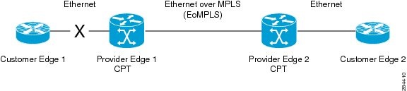
The Remote Ethernet Port Shutdown feature allows a service provider edge router on the local end of an Ethernet over MPLS (EoMPLS) pseudowire to detect a remote link failure and cause the shutdown of the Ethernet port on the local customer edge router. Shutting down the Ethernet port on the local customer edge router prevents or mitigates a condition where that router would otherwise lose data by forwarding traffic continuously to the remote failed link, especially if the link was configured as a static IP route.
The Remote Ethernet Port Shutdown feature is available for both GE and 10GE UNIs (User Network Interfaces). If a UNI port connected to a pseudowire detects the failure, then the opposite UNI port connected to the same pseudowire performs a laser shutdown. If both the working or protect LSPs go down, then both the UNI ports connected to the Multiprotocol Label Switching – Traffic Engineering (MPLS-TE) or Multiprotocol Label Switching – Transport Profile (MPLS-TP) tunnel perform a laser shutdown.
The following figure illustrates a condition in an EoMPLS network, with a down Layer 2 tunnel link between a customer edge router (Customer Edge 1) and the service provider edge (Provider Edge 1). A customer edge router on the far side of the Layer 2 tunnel (Customer Edge 2), continues to forward traffic to Customer Edge 1 through the L2 tunnel.
Prior to this feature, the Provider Edge 2 router could not detect a failed remote link. The traffic forwarded from Customer Edge 2 to Customer Edge 1 would be lost.
With the Remote Ethernet Port Shutdown feature, the Provider Edge 2 router detects the remote link failure and causes a shutdown of the local Customer Edge 2 Ethernet port. When the remote L2 tunnel link is restored, the local interface is automatically restored as well. The possibility of data loss is thus diminished.
With reference to the above figure, the Remote Ethernet Port Shutdown sequence is generally described as follows:
The remote link between Customer Edge 1 and Provider Edge 1 fails.
The Provider Edge 2 running Cisco CPT detects the remote link failure and disables the transmit laser on the card interface connected to Customer Edge 2.
A remote alarm or local fault alarm is received by Customer Edge 2 causing Customer Edge 2 to bring down the interface.
Provider Edge 2 maintains its interface with Customer Edge 2 in an Up state.
When the remote link and EoMPLS connection is restored, the Provider Edge 2 router enables the transmit laser.
The Customer Edge 2 router brings up its interface.
The Remote Ethernet Port Shutdown feature is enabled by default for EoMPLS, and can be disabled using no remote link failure notification command in the xconnect sub–mode. Use the show ip interface brief command in privileged EXEC mode to display the status of all remote Layer 2 tunnel links. Use the show interface command in privileged EXEC mode to show the status of the Layer 2 tunnel on a specific interface.
Note | The no remote link failure notification command does not notify clients when the remote attachment circuit status is down. |
Restrictions
The following restrictions apply to the Remote Ethernet Port Shutdown feature:
- Applies only to xconnect that is configured under default encapsulation Ethernet Flow Point (EFP).
- Applies only to Virtual Private Wired Service (VPWS) and not Virtual Private LAN Service (VPLS) circuits.
- Applies to attachment circuit failures only on VPWS port-based pseudowire; VLAN-based pseudowires do not support this feature.
- Supports only when the pseudowire class type is Ethernet.
- Requires fault detection protocol like LDP or BFD to be enabled for static or dynamic pseudowire.
- Requires OAM, BFD over VCCV, or BFD over VCCV AC signaling to be enabled if the pseudowire is configured over the MPLS–TP tunnel.
Soak Time
The soak time is the duration when the interface that failed does not restore operation even when the failure is rectified. Soak time can be configured even if the Remote Ethernet Port Shutdown feature is disabled. The soak time will be effective only when the Remote Ethernet Port Shutdown feature is enabled. The default value of soak time is 10 seconds. The range is from 0 to 300 seconds.
The soak time applies only to the individual ports. The soak time does not apply to the ports of a channel group if the channel group is configured as an attachment circuit.
- DLP-J325 Configure Remote Ethernet Port Shutdown for Ports Using Cisco IOS Commands
- DLP-J326 Configure Remote Ethernet Port Shutdown for Ports Using CTC
DLP-J325 Configure Remote Ethernet Port Shutdown for Ports Using Cisco IOS Commands
| Purpose | This procedure configures Remote Ethernet Port Shutdown for ports using Cisco IOS commands. |
| Tools/Equipment | None |
| Prerequisite Procedures | DLP-J90 Create a Pseudowire Using Cisco IOS Commands |
| Required/As Needed | As needed |
| Onsite/Remote | Onsite |
| Security Level | Provisioning or higher |
| Command or Action | Purpose | |
|---|---|---|
| Step 1 | enable Example:Router> enable | Enables privileged EXEC mode. |
| Step 2 | configure terminal Example:Router# configure terminal | Enters global configuration mode. |
| Step 3 | interface type number Example:Router(config)# interface TenGigabitEthernet4/1 | Specifies the interface to configure and enters interface configuration mode. |
| Step 4 | local link notification soak-duration duration Example:Router(config-if)# local link notification soak-duration 30 | Specifies the soak time for this interface in seconds. The default value of soak time is 10 seconds. The range is from 0 to 300 seconds. |
| Step 5 | service instance serviceinstanceid ethernet Example:Router(config-if)# service instance 100 ethernet | Specifies the Ethernet service instance and enters service instance configuration mode. |
| Step 6 | encapsulation default Example:Router(config-if-srv)# encapsulation default | Enables the EFP to accept all the packets (tagged and untagged). |
| Step 7 | xconnect peer-ip-address vcid encapsulation mpls pw-class pw-class-name [sequencing {transmit | receive | both}] Example:Router(config-if-srv)# xconnect 10.131.191.252 100 encapsulation mpls pw-class class1 | Binds an attachment circuit to a pseudowire VC. |
| Step 8 | remote link failure notification Example:Router(config-if-ether-vc-xconn)# remote link failure notification | Enables Remote Ethernet Port Shutdown on this interface. The no version of this command disables Remote Ethernet Port Shutdown on this interface. |
| Step 9 | exit Example:Router(config-if-ether-vc-xconn)# exit | Exits xconnect configuration mode. |
| Step 10 | exit Example:Router(config-if-srv)# exit | Exits service instance configuration mode. |
| Step 11 | exit Example:Router(config-if)# exit | Exits interface configuration mode. |
| Step 12 | Return to your originating procedure (NTP). | — |
DLP-J326 Configure Remote Ethernet Port Shutdown for Ports Using CTC
| Purpose | This procedure configures Remote Ethernet Port Shutdown for ports using CTC. |
| Tools/Equipment | None |
| Prerequisite Procedures | DLP-J91 Create a Pseudowire Using CTC |
| Required/As Needed | As needed |
| Onsite/Remote | Onsite or remote |
| Security Level | Provisioning or higher |
| Step 1 | Complete the NTP-J22 Log into CTC procedure at a node where you want to configure Remote Ethernet Port Shutdown for ports. | ||
| Step 2 | Right-click the fabric or line card and choose Open Packet Transport System View. The Packet Transport System View dialog box appears. | ||
| Step 3 | Click the Provisioning tab. | ||
| Step 4 | In the left pane, click Port Configuration. | ||
| Step 5 | In the Port Configurations area, expand the slot of the fabric card or line card, or the FOG of the CPT 50 panel to view the port configurations. | ||
| Step 6 | Check the Remote Link Failure Notification Enable check box against the ports to enable Remote Ethernet Port Shutdown for the ports.
| ||
| Step 7 | Enter the soak duration in the Soak Time field for each port. The default value of Soak Time is 10 seconds. The range is from 0 to 300 seconds. | ||
| Step 8 | Click Apply. | ||
| Step 9 | Return to your originating procedure (NTP). |
Understanding BFD Control Channel over VCCV
MPLS pseudowires enable Layer 2 traffic to be carried over an IP/MPLS core network. The Bidirectional Forwarding Detection (BFD) control channel over Virtual Circuit Connection Verification (VCCV) feature provides OAM functions for MPLS pseudowires.
You can enable BFD control channel over VCCV feature using the NTP-J35 Configure BFD Control Channel over VCCV Using Cisco IOS Commands or DLP-J89 Create a Pseudowire Class Using CTC.
Note | This feature provides support only for VCCV type 1. VCCV type 1 is in-band VCCV and can be used only for MPLS pseudowires that use a control word. |
The BFD protocol can be used to provide OAM functionality to the MPLS protocol. The VCCV provides a control channel associated with the pseudowire to provide OAM functions over that pseudowire. BFD can use the VCCV control channel as a pseudowire fault mechanism to detect data plane failures. BFD can also use the VCCV control channel to carry the fault status of an attachment circuit (AC).
MPLS pseudowires can dynamically signal or statically configure virtual circuit (VC) labels. In dynamically signaled pseudowires, the control channel (CC) types and connection verification (CV) types are also signaled. In statically configured pseudowires, the CC and CV types must be configured on both ends of the pseudowire.
The CC types define whether VCCV packets are in-band or out-of-band for the pseudowire. The CV types define whether BFD monitoring is required for the pseudowire. If BFD monitoring is required for the pseudowire, the CV types also define how the BFD packets are encapsulated and whether BFD provides status signaling functionality.
Any protocol that requires BFD monitoring must register with BFD as a client. For example, the the Xconnect protocol registers as a BFD client, and BFD assigns a client ID to Xconnect. The Xconnect uses this client ID to create the BFD sessions that monitor the pseudowire.
BFD can detect forwarding failures (end-to-end) in the pseudowire path. When BFD detects a failure in the pseudowire forwarding path, it notifies the Xconnect client that created the session. In addition, BFD can signal the status in any concatenated path or AC, to the remote device where the BFD session is terminated.
Restrictions of BFD Control Channel over VCCV
The BFD Control Channel over VCCV feature supports only VCCV type 1 without IP/User Datagram Protocol (UDP) encapsulation.
Any Transport over Multiprotocol Label Switching (AToM) is the only transport protocol supported by the BFD Control Channel over VCCV.
Layer 2 Transport Protocol version 3 (L2TPv3) is not supported.
Pseudowire redundancy is not supported.
NTP-J35 Configure BFD Control Channel over VCCV Using Cisco IOS Commands
| Purpose | This procedure configures VCCV BFD to run on pseudowires. |
| Tools/Equipment | None |
| Prerequisite Procedures | |
| Required/As Needed | As needed |
| Onsite/Remote | Onsite or remote |
| Security Level | Provisioning or higher |
| Command or Action | Purpose | |
|---|---|---|
| Step 1 | enable Example:Router> enable | Enables privileged EXEC mode. |
| Step 2 | configure terminal Example:Router# configure terminal | Enters global configuration mode. |
| Step 3 | pseudowire-class name Example: Router(config)# pseudowire-class vccv-bfd1 | Specifies the name of the pseudowire class and enters pseudowire class configuration mode. |
| Step 4 | encapsulation mpls Example:Router(config-pw-class)# encapsulation mpls | Specifies that the MPLS is used as the data encapsulation method for tunneling Layer 2 traffic over the pseudowire. You must specify MPLS encapsulation as part of the xconnect command or as part of a pseudowire class for the virtual circuits to work properly. |
| Step 5 | protocol {ldp | none} Example:Router(config-pw-class)# protocol none | Specifies that no signaling is configured and that manually configured sessions are used. To configure static pseudowires, you must specify the none keyword. |
| Step 6 | vccv {control-word | router-alert | ttl} Example:Router(config-pw-class)# vccv control-word | Sets the MPLS pseudowire control channel (CC) type. For MPLS pseudowires that use a connection verification (CV) type that does not include IP/UDP headers, you must set the CC type to CC type 1: pseudowire control word. |
| Step 7 | vccv bfd template name {udp | raw-bfd} Example:Router(config-pw-class)# vccv bfd template bfdtemplate1 raw-bfd | Enables BFD over VCCV for the pseudowire class. |
| Step 8 | vccv bfd status signaling Example:Router(config-pw-class)# vccv bfd status signaling | Enables status signaling for BFD over VCCV. |
| Step 9 | exit Example:Router(config-pw-class)# exit | Exits pseudowire class configuration mode and returns to global configuration mode. |
| Step 10 | interface type number Example:Router(config)# interface TenGigabitEthernet4/1 | Specifies the interface to configure and enters interface configuration mode. |
| Step 11 | service instance serviceinstanceid ethernet Example:Router(config-if)# service instance 100 ethernet | Specifies the service instance and enters service instance configuration mode. |
| Step 12 | encapsulation dot1q vlan-id Example:Router(config-if-srv)# encapsulation dot1q 100 | Enables the Ethernet Flow Point (EFP) to accept 802.1Q VLAN packets. |
| Step 13 | xconnect peer-ip-address vc-id {encapsulation mpls [manual] | pw-class pw-class-name } [pw-class pw-class-name] [sequencing {transmit | receive | both}] Example:Router(config-if-srv)# xconnect 10.0.0.7 100 pw-class vccv-bfd1 | Binds an attachment circuit (AC) to a pseudowire, configures a static pseudowire, and specifies the pseudowire class. |
| Step 14 | Return to your originating procedure (NTP). Example:— |
 Feedback