Configuring Ethernet OAM, Connectivity Fault Management, and Y.1731

This chapter describes Ethernet OAM, Connectivity Fault Management (CFM), and Y.1731 features. This chapter also describes procedures to configure Ethernet OAM, CFM, and Y.1731.

This chapter includes the following topics:

Ethernet Link OAM Overview

Ethernet Link Operations, Administration, and Maintenance (OAM) is a protocol for installing, monitoring, and troubleshooting Ethernet metropolitan-area networks (MANs) and Ethernet WANs. It relies on an optional sublayer in the data link layer of the Open Systems Interconnection (OSI) model, as specified in IEEE 802.3ah-2004 Clause 57.

Ethernet Link OAM enables service providers to monitor and troubleshoot a single physical (or emulated) Ethernet link. It supports link level verification, monitoring, and troubleshooting between two Ethernet devices. It is particularly valuable in the 'first mile' connection to the customer demarcation.

Understanding Ethernet Link OAM

Ethernet link OAM can be implemented on any full-duplex point-to-point or emulated point-to-point Ethernet link. A system-wide implementation is not required; OAM can be deployed for part of a system; that is, on specific interfaces.

Normal link operation does not require Ethernet link OAM. OAM frames, called OAM protocol data units (PDUs), use the slow protocol destination MAC address 0180.c200.0002. They are intercepted by the MAC sublayer and cannot propagate beyond a single hop within an Ethernet network.

Ethernet link OAM is a relatively slow protocol with modest bandwidth requirements. The frame transmission rate is limited to a maximum of 10 frames per second; therefore, the impact of OAM on normal operations is negligible. However, when link monitoring is enabled, the CPU must poll error counters frequently. In this case, the required CPU cycles will be proportional to the number of interfaces that have to be polled.

Two major components, the OAM client and the OAM sublayer, make up Ethernet Link OAM. The following two sections describe these components.

OAM Client

The OAM client is responsible for establishing and managing Ethernet link OAM on a link. It also enables and configures the OAM sublayer. During the OAM discovery phase, the OAM client monitors OAM PDUs received from the remote peer and enables OAM functionality on the link based on the local and remote state as well as configuration settings. After the discovery phase (at steady state), the OAM client is also responsible for managing the rules of response to OAM PDUs and the OAM remote loopback mode.

OAM Sublayer

The OAM sublayer presents two standard IEEE 802.3 MAC service interfaces: one facing the superior sublayers, which include the MAC client (or link aggregation), and the other interface facing the subordinate MAC control sublayer. The OAM sublayer provides a dedicated interface for passing OAM control information and OAM PDUs to and from a client. The OAM sublayer is made up of three components: control block, multiplexer, and packet parser (p-parser).

The control block provides the interface between the OAM client and other blocks internal to the OAM sublayer. The control block runs the discovery process, which detects the existence and capabilities of remote OAM peers. It also includes the transmit process that governs the transmission of OAM PDUs to the multiplexer and a set of rules that govern the receipt of OAM PDUs from the p-parser.

The multiplexer manages frames generated (or relayed) from the MAC client, control block, and p-parser. The multiplexer passes through frames generated by the MAC client untouched. It passes OAM PDUs generated by the control block to the subordinate sublayer; such as the MAC sublayer. Similarly, the multiplexer passes loopback frames from the p-parser to the same subordinate sublayer when the interface is in OAM remote loopback mode.

The p-parser classifies frames as OAM PDUs, MAC client frames, or loopback frames and then dispatches each class to the appropriate entity. OAM PDUs are sent to the control block; MAC client frames are passed to the superior sublayer; and loopback frames are dispatched to the multiplexer.

Benefits of Ethernet Link OAM

Ethernet Link OAM provides the following benefits:

  • Competitive advantage for service providers.

  • Standardized mechanism to monitor the health of a link and perform diagnostics.

NTP-J114 Configure EFM Using Cisco IOS Commands

Purpose

This procedure configures EFM using Cisco IOS commands.

Tools/Equipment None
Prerequisite Procedures None
Required/As Needed As needed
Onsite/Remote Onsite or remote
Security Level Provisioning or higher
Procedure
Perform any of the following procedures as needed:

Stop. You have completed this procedure.


NTP-J115 Configure EFM Using CTC

Purpose

This procedure configures EFM using CTC.

Tools/Equipment None
Prerequisite Procedures None
Required/As Needed As needed
Onsite/Remote Onsite or remote
Security Level Provisioning or higher
Procedure
Perform any of the following procedures as needed:

Stop. You have completed this procedure.


DLP-J320 Enable or Disable Ethernet Link OAM on an Interface Using Cisco IOS Commands

Purpose

This procedure enables or disables Ethernet Link OAM on an interface using Cisco IOS commands.

Tools/Equipment None
Prerequisite Procedures None
Required/As Needed As needed
Onsite/Remote Onsite or remote
Security Level Provisioning or higher
Procedure
     Command or ActionPurpose
    Step 1enable


    Example:Router> enable 

    Enables privileged EXEC mode.

    • Enter your password if prompted.

     
    Step 2configure terminal


    Example:Router# configure terminal 

    Enters global configuration mode.

     
    Step 3interface type number


    Example: Router(config)# interface TenGigabitEthernet4/1 

    Specifies the interface to configure and enters interface configuration mode.

     
    Step 4 ethernet oam [max-rate oampdus | min-rate num-seconds| mode {active | passive} | timeout seconds]

    Example: Router(config-if)# ethernet oam 

    Enables Ethernet Link OAM on the interface.

    The no form of this command disables Ethernet Link OAM on the interface.

     
    Step 5exit


    Example:Router(config-if)# exit 

    Exits interface configuration mode and returns to global configuration mode.

     
    Step 6Return to your originating procedure (NTP).   

    DLP-J314 Enable or Disable Ethernet Link OAM on a Port Using CTC

    Purpose

    This procedure enables or disables Ethernet link OAM on a port using CTC.

    Tools/Equipment None
    Prerequisite Procedures None
    Required/As Needed As needed
    Onsite/Remote Onsite or remote
    Security Level Provisioning or higher
    Procedure
      Step 1   Complete the NTP-J22 Log into CTC procedure at a node where you want to enable or disable Ethernet link OAM on a port.
      Step 2   Right-click the fabric or line card and choose Open Packet Transport System View.
      Step 3   The Packet Transport System View dialog box appears. Click the Provisioning > EFM > Configuration tabs.
      Step 4   In the Configuration area, expand the appropriate slot and select the port where you want to enable the Ethernet link OAM.
      Step 5   From the EFM State drop-down list, choose Enabled to enable Ethernet link OAM on the selected port.

      Choose Disabled to disable Ethernet link OAM on the selected port.

      Note    Ethernet link OAM is disabled by default on a port.
      Step 6   In the Configuration area, expand the appropriate slot and modify any of the parameters as described in the following table.
      Table 1 Ethernet Link OAM Parameters
      Parameter Description Options
      Port (Display only) Displays the port number (n-n) and rate.
      Mode (Optional) Sets the OAM client mode on the interface.
      • Active—Sets the OAM client mode to active on the interface which was previously in passive mode. Active is the default mode.

      • Passive—Sets the OAM client mode to passive on the interface. In passive mode, a device cannot initiate discovery, inquire about variables, or set loopback mode.

      Transmission Rate Minimum (Optional) Sets the minimum rate, in seconds, at which OAM PDUs are transmitted. That is, the number of seconds during which at least one OAM PDU must be transmitted. The valid values range from 1 to 10 seconds.
      Transmission Rate Maximum (Optional) Sets the maximum rate, in seconds, at which OAM PDUs are transmitted. That is, the number of seconds during which OAM PDUs must be transmitted. The valid values range from 1 to 10 seconds.The default is 10 seconds.
      Session Timer (Optional) Specifies the amount of time, in seconds, after which a device declares its OAM peer to be nonoperational and resets its state machine. That is, the number of seconds a device waits for its OAM peer to respond. The valid values range from 2 to 30 seconds.The default is 5 seconds.
      Step 7   Return to your originating procedure (NTP).

      Ethernet Link OAM Features

      The Cisco CPT supports the following Ethernet link OAM features:

      Discovery

      Discovery is the first phase of Ethernet link OAM where it identifies the devices in the network and their OAM capabilities. Discovery uses information OAM PDUs. During the discovery phase, the following information is advertised within periodic information OAM PDUs:

      • OAM mode—Conveyed to the remote OAM entity. The mode can be either active or passive and can be used to determine device functionality.

      • OAM configuration (capabilities)—Advertises the capabilities of the local OAM entity. With this information a peer can determine what functions are supported and accessible; for example, loopback capability.

      • OAM PDU configuration—Includes the maximum OAM PDU size for receipt and delivery. This information along with the rate limiting of 10 frames per second can be used to limit the bandwidth allocated to the OAM traffic.

      • Platform identity—Specifies a combination of an organization unique identifier (OUI) and 32-bits of vendor-specific information. OUI allocation, controlled by the IEEE, is typically the first three bytes of a MAC address.

      Discovery includes an optional phase in which the local station can accept or reject the configuration of the peer OAM entity. For example, a node may require its partner support loopback capability to be accepted in the management network. These policy decisions may be implemented as vendor-specific extensions.

      Link Monitoring

      Link monitoring in Ethernet Link OAM detects and indicates link faults under a variety of conditions. Link monitoring uses the event notification OAM PDU and sends events to the remote OAM entity when there are problems detected on the link. The error events include the following:

      • Error Frame (error frames per second)—The number of frame errors detected during a specified period that exceed a threshold.

      • Error Frame Period (error frames per n frames)—The number of frame errors within the last n frames that exceed a threshold.

      • Error Frame Seconds Summary (error seconds per m seconds)—The number of error seconds (1-second intervals with at least one frame error) within the last m seconds that exceed a threshold.

      Because IEEE 802.3ah OAM does not provide a guaranteed delivery of any OAM PDU, the event notification OAM PDU may be sent multiple times to reduce the probability of a lost notification. A sequence number is used to recognize duplicate events.

      DLP-J321 Enable or Disable Link Monitoring Support on an Interface Using Cisco IOS Commands

      Purpose

      This procedure enables or disables link monitoring support on an interface using Cisco IOS Commands.

      Tools/Equipment None
      Prerequisite Procedures None
      Required/As Needed As needed
      Onsite/Remote Onsite or remote
      Security Level Provisioning or higher
      Procedure
         Command or ActionPurpose
        Step 1enable


        Example:Router> enable 

        Enables privileged EXEC mode.

        • Enter your password if prompted.

         
        Step 2configure terminal


        Example:Router# configure terminal 

        Enters global configuration mode.

         
        Step 3interface type number


        Example: Router(config)# interface TenGigabitEthernet4/1 

        Specifies the interface to configure and enters interface configuration mode.

         
        Step 4 ethernet oam link-monitor supported


        Example: Router(config-if)# ethernet oam link-monitor supported 

        Enables link monitoring support on the interface.

        The no form of this command disables link monitoring support on the interface.

         
        Step 5exit


        Example:Router(config-if)# exit 

        Exits interface configuration mode and returns to global configuration mode.


        DLP-J315 Enable or Disable Link Monitoring Support on an Interface Using CTC

        Purpose

        This procedure enables or disables support for link monitoring on an interface using CTC.

        This procedure helps establish an OAM session for performing OAM functions, such as remote loopback. For example, if the device is connected to a third-party device that does not support link monitoring, then link monitoring support must be disabled on the device to establish an OAM session with the third-party device.

        Tools/Equipment None
        Prerequisite Procedures None
        Required/As Needed As needed
        Onsite/Remote Onsite or remote
        Security Level Provisioning or higher
        Procedure
          Step 1   Complete the NTP-J22 Log into CTC procedure at a node where you want to enable or disable link monitoring support on an interface.
          Step 2   Right-click the fabric or line card and choose Open Packet Transport System View.
          Step 3   The Packet Transport System View dialog box appears. Click the Provisioning > EFM > Link Monitoring tabs
          Step 4   In the Link Monitoring area, expand the appropriate slot and select the port where you want to enable link monitoring.
          Step 5   From the Support drop-down list, choose Support to enable link monitoring support or choose No support to disable link monitoring support on the interface.
          Step 6   Return to your originating procedure (NTP).

          DLP-J322 Enable or Disable Link Monitoring on an Interface Using Cisco IOS Commands

          Purpose

          This procedure enables or disables link monitoring on an interface using Cisco IOS commands.

          Tools/Equipment None
          Prerequisite Procedures None
          Required/As Needed As needed
          Onsite/Remote Onsite or remote
          Security Level Provisioning or higher
          Procedure
             Command or ActionPurpose
            Step 1enable


            Example:Router> enable 

            Enables privileged EXEC mode.

            • Enter your password if prompted.

             
            Step 2configure terminal


            Example:Router# configure terminal 

            Enters global configuration mode.

             
            Step 3interface type number


            Example: Router(config)# interface TenGigabitEthernet4/1 

            Specifies the interface to configure and enters interface configuration mode.

             
            Step 4 ethernet oam [max-rate oampdus | min-rate num-seconds| mode {active | passive} | timeout seconds]

            Example: Router(config-if)# ethernet oam 

            Enables Ethernet OAM on the interface.

             
            Step 5 ethernet oam link-monitor on


            Example: Router(config-if)# ethernet oam link-monitor on 

            Enables link monitoring on the interface.

            The no form of this command disables link monitoring on the interface.

             
            Step 6exit


            Example:Router(config-if)# exit 

            Exits interface configuration mode and returns to global configuration mode.


            DLP-J316 Enable or Disable Link Monitoring on an Interface Using CTC

            Purpose

            This procedure enables or disables link monitoring on an interface using CTC.

            Tools/Equipment None
            Prerequisite Procedures None
            Required/As Needed As needed
            Onsite/Remote Onsite or remote
            Security Level Provisioning or higher

            Note


            Link monitoring is enabled by default when Ethernet Link OAM is enabled on a interface.


            When link monitoring is enabled, the interface sends event OAM PDUs when errors occur and interprets event OAM PDUs from the remote peer. Link monitoring can be effective only if both the local client and remote peer agree to support it.

            Procedure
              Step 1   Complete the NTP-J22 Log into CTC procedure at a node where you want to enable or disable link monitoring on an interface.
              Step 2   Right-click the fabric or line card and choose Open Packet Transport System View.
              Step 3   The Packet Transport System View dialog box appears. Click the Provisioning > EFM > Link Monitoring tabs
              Step 4   In the Link Monitoring area, expand the appropriate slot and select the port where you want to enable link monitoring.
              Step 5   From the Enable drop-down list, choose Enable to enable link monitoring or choose Disable to disable link monitoring on the interface.
              Step 6   Return to your originating procedure (NTP).

              DLP-J323 Configure Link Monitoring Parameters on an Interface Using Cisco IOS Commands

              Purpose

              This procedure configures link monitoring parameters on an interface using Cisco IOS Commands.

              Note    Perform this optional task to specify link monitoring parameters. Steps 4 through 11 can be performed in any sequence.
              Tools/Equipment None
              Prerequisite Procedures None
              Required/As Needed As needed
              Onsite/Remote Onsite or remote
              Security Level Provisioning or higher
              Procedure
                 Command or ActionPurpose
                Step 1enable


                Example:Router> enable 

                Enables privileged EXEC mode.

                • Enter your password if prompted.

                 
                Step 2configure terminal


                Example:Router# configure terminal 

                Enters global configuration mode.

                 
                Step 3interface type number


                Example: Router(config)# interface TenGigabitEthernet4/1 

                Specifies the interface to configure and enters interface configuration mode.

                 
                Step 4 ethernet oam [max-rate oampdus | min-rate num-seconds| mode {active | passive} | timeout seconds]

                Example: Router(config-if)# ethernet oam 

                Enables Ethernet link OAM on the interface.

                 
                Step 5 ethernet oam link-monitor high-threshold action error-disable-interface


                Example: Router(config-if)# ethernet oam link-monitor high-threshold action error-disable-interface 

                Sets the interface to the blocking or disabled state when a high threshold for an error is exceeded.

                 
                Step 6 ethernet oam link-monitor frame {threshold {high { none | high-frames} | low low-frames} | window milliseconds}

                Example: Router(config-if)# ethernet oam link-monitor frame window 399 

                Configures, in milliseconds, the number for error frames that trigger an action when reached.

                 
                Step 7 ethernet oam link-monitor frame-period {threshold {high {none | high-frames} | low low-frames} | window frames}


                Example: Router(config-if)# ethernet oam link-monitor frame-period threshold high 599 

                Configures the number of frames to be polled. The frame period is a user-defined parameter.

                 
                Step 8 ethernet oam link-monitor frame-seconds {threshold {high {none | high-frames} | low low-frames} | window milliseconds}

                Example: Router(config-if)# ethernet oam link-monitor frame-seconds window 699 

                Configures a period of time, in milliseconds, during which error frames are counted.

                 
                Step 9 ethernet oam link-monitor receive-crc {threshold {high {none | high-frames} | low low-frames} | window milliseconds}

                Example: Router(config-if)# ethernet oam link-monitor receive-crc window 99 

                Configures an Ethernet OAM interface to monitor ingress frames with cyclic redundancy check (CRC) errors for a period of time.

                 
                Step 10 ethernet oam link-monitor transmit-crc {threshold {high {none | high-frames} | low low-frames} | window milliseconds}

                Example: Router(config-if)# ethernet oam link-monitor transmit-crc threshold low 199 

                Configures an Ethernet OAM interface to monitor egress frames with CRC errors for a period of time (in milliseconds).

                 
                Step 11 ethernet oam link-monitor symbol-period {threshold {high {none | high-symbols} | low low-symbols} | window symbols}

                Example: Router(config-if)# ethernet oam link-monitor symbol-period threshold high 299 

                Configures a threshold or window for error symbols, in number of symbols.

                 
                Step 12exit


                Example:Router(config-if)# exit 

                Exits interface configuration mode and returns to global configuration mode.


                DLP-J317 Configure Link Monitoring Parameters on an Interface Using CTC

                Purpose

                This procedure configures the link monitoring parameters on an interface using CTC.

                Tools/Equipment None
                Prerequisite Procedures None
                Required/As Needed As needed
                Onsite/Remote Onsite or remote
                Security Level Provisioning or higher
                Procedure
                  Step 1   Complete the NTP-J22 Log into CTC procedure at a node where you want to configure link monitoring parameters on an interface.
                  Step 2   Right-click the fabric or line card and choose Open Packet Transport System View.
                  Step 3   The Packet Transport System View dialog box appears. Click the Provisioning > EFM > Link Monitoring tabs
                  Step 4   In the Link Monitoring area, expand the appropriate slot and modify any of the parameters as described in the following table.
                  Table 2 Link Monitoring Parameters
                  Parameter Description Options
                  Port (Display only) Displays the port number (n-n) and rate.
                  FT Min Frame Threshold Minimum–Sets a low error frame threshold in number of frames. The valid values range from 0 to 65535 seconds or frames per second. The default is 1 second.
                  FT Max Frame Threshold Maximum–Sets a high error frame threshold in number of frames. Integer in the range of 1 to 65535 that is the high threshold in number of frames.
                  Frame Window Sets a window and period of time during which error frames are counted. Sets a window and period of time during which error frames are counted. Integer in the range of 10 to 600 that represents a number of milliseconds in a multiple of 100. The default is 100.
                  FPT Min Frame Period Threshold Minimum–Sets a low threshold for the error frame period in number of frames. Integer in the range of 0 to 65535 that is the low threshold in number of frames. The default is 1.
                  FPT Max Frame Period Threshold Maximum–Sets a high threshold for the error frame period in number of frames. Integer in the range of 1 to 65535 that is the high threshold in number of frames. There is no default. The high threshold must be configured.
                  FP Window Frame Period Window–Sets a polling window and window size. Integer in the range of 1 to 65535 that is the window size in number of frames. Each value is a multiple of 10000. The default is 1000.
                  FST Min Frame Seconds Threshold Minimum–Sets a low error frame-seconds threshold in number of seconds. Integer in the range of 1 to 900 that sets the low threshold in number of frames. The default is 1.
                  FST Max Frame Seconds Threshold Maximum–Sets a high error frame-seconds threshold in number of seconds. Integer in the range of 1 to 900 that is the high threshold in number of frames. There is no default. The high threshold must be configured.
                  FS Window Frame Seconds Window–Sets a polling window during which error frames are counted. Integer in the range of 100 to 9000 that represents a number of milliseconds in a multiple of 100. The default is 1000.
                  SPT Min Symbol Period Threshold Minimum–Sets a low threshold for the period in number of error symbols. Integer in the range of 0 to 65535 that is the low threshold in number of symbols.
                  SPT Max Symbol Period Threshold Maximum–Sets a high threshold for the period in number of error symbols. Integer in the range of 1 to 65535 that is the high threshold in number of symbols. There is no default. The high threshold must be configured.
                  SP Window Symbol Period Window-Sets a window and window size. Integer in the range of 1 to 65535 that is the window size in number of symbols. Each value represents one million.
                  RCRCT Min Receive CRC Threshold Minimum–Sets a low threshold. Integer in the range of 0 to 65535 that sets the low threshold in number of frames. The default is 10.
                  RCRCT Max Receive CRC Threshold Maximum–Sets a high threshold in number of frames. Integer in the range of 1 to 65535 that is the high threshold in number of frames.
                  RCRC Window Receive CRC Window–Sets a window and period of time during which frames with CRC errors are counted. Integer in the range of 10 to 1800 that represents a number of milliseconds in a multiple of 100. The default is 1000.
                  TCRCT Min Transmit CRC Threshold Minimum–Sets a low threshold. Integer in the range of 0 to 65535 that sets the low threshold in number of frames. The default is 10.
                  TCRCT Max Transmit CRC Threshold Maximum-Sets a high threshold in number of frames. Integer in the range of 1 to 65535 that is the high threshold in number of frames.
                  TCRC Window Transmit CRC Window-Sets a window and period of time during which frames with transmit CRC errors are counted. Integer in the range of 10 to 1800 that represents a number of milliseconds in a multiple of 100. The default is 100.
                  HT Action High Threshold Action–Provides an automatic failover of traffic from one port in an EtherChannel to another port in the same EtherChannel when one of the ports in the channel exceeds the high threshold for an error within the specified interval. The port failover occurs only if at least one operational port is in the EtherChannel. If the failed port is the last port in the EtherChannel, the port is moved into error-disable state and continues to pass traffic regardless of the types of errors received.
                  • NONE

                  • Error Disable

                  Step 5   Return to your originating procedure (NTP).

                  Remote Failure Indication

                  Faults in Ethernet connectivity that are caused by slowly deteriorating quality are difficult to detect. Ethernet Link OAM provides a mechanism for an OAM entity to convey these failure conditions to its peer via specific flags in the OAM PDU. The following failure conditions can be communicated:

                  • Link Fault–Loss of signal is detected by the receiver. A link fault is sent every second in the information OAM PDU. Link fault applies only when the physical sublayer is capable of independently transmitting and receiving signals.

                  • Dying Gasp–An unrecoverable condition has occurred; for example, a power failure. This type of condition is vendor specific. A notification about the condition may be sent immediately and continuously.

                  • Critical Event–An unspecified critical event has occurred. This type of event is vendor specific. A critical event may be sent immediately and continuously.

                  DLP-J325 Configure the Port for Remote Link Failure Indication Using Cisco IOS Commands

                  Purpose

                  This procedure configures the port for remote link failure indication using Cisco IOS commands.

                  Tools/Equipment None
                  Prerequisite Procedures None
                  Required/As Needed As needed
                  Onsite/Remote Onsite or remote
                  Security Level Provisioning or higher
                  Procedure
                     Command or ActionPurpose
                    Step 1enable


                    Example:Router> enable 

                    Enables privileged EXEC mode.

                    • Enter your password if prompted.

                     
                    Step 2configure terminal


                    Example:Router# configure terminal 

                    Enters global configuration mode.

                     
                    Step 3interface type number


                    Example: Router(config)# interface TenGigabitEthernet4/1 

                    Specifies the interface to configure and enters interface configuration mode.

                     
                    Step 4 ethernet oam remote-failure {critical-event | dying-gasp | link-fault} action {error-block-interface | error-disable-interface}

                    Example: Router(config-if)# ethernet oam remote-failure critical-event action error-block-interface 

                    Sets the interface to the blocking state when a critical event occurs.

                     
                    Step 5exit


                    Example:Router(config-if)# exit 

                    Exits interface configuration mode and returns to global configuration mode.


                    DLP-J319 Configure the Port for Remote Link Failure Indication Using CTC

                    Purpose

                    This procedure configures the port for remote link failure indication using CTC.

                    Tools/Equipment None
                    Prerequisite Procedures None
                    Required/As Needed As needed
                    Onsite/Remote Onsite or remote
                    Security Level Provisioning or higher
                    Procedure
                      Step 1   Complete the NTP-J22 Log into CTC procedure at a node where you want to configure the port for remote link failure indication.
                      Step 2   Right-click the fabric or line card and choose Open Packet Transport System View.
                      Step 3   The Packet Transport System View dialog box appears. Click the Provisioning > EFM > Configuration tabs
                      Step 4   In the Configuration area, expand the appropriate slot and modify any of the parameters as described in the following table.
                      Table 3 Remote Link Failure Indication Parameters
                      Parameter Description Options
                      Link Fault Detects the loss of signal by the receiver.
                      • None
                      • Error Block
                      • Error Disable
                      Critical Event Sends the critical event notification when an unspecified critical event has occurred.
                      • None
                      • Error Disable
                      Dying Gasp Sends the notification when an unrecoverable condition has occurred; for example, a power failure.
                      • None
                      • Error Block
                      • Error Disable
                      Step 5   Return to your originating procedure (NTP).

                      Remote Loopback

                      An OAM entity can put its remote peer into loopback mode using the loopback control OAM PDU. Loopback mode helps an administrator ensure the quality of links during installation or when troubleshooting. In loopback mode, every frame received is transmitted back on the same port except for OAM PDUs and pause frames. The periodic exchange of OAM PDUs must continue during the loopback state to maintain the OAM session.

                      The loopback command is acknowledged by responding with an information OAM PDU with the loopback state indicated in the State field. This acknowledgement allows an administrator, for example, to estimate if a network segment can satisfy a service-level agreement. Acknowledgement makes it possible to test delay, jitter, and throughput.

                      When an interface is set to the remote loopback mode the interface no longer participates in any other Layer 2 or Layer 3 protocols; for example Spanning Tree Protocol (STP) or Open Shortest Path First (OSPF). This is because when two connected ports are in a loopback session, no frames other than the OAM PDUs are sent to the CPU for software processing. The non-OAM PDU frames are either looped back at the MAC level or discarded at the MAC level.

                      From a user perspective, an interface in a loopback mode is in a link-up state.

                      DLP-J367 Set Up Remote Loopback Timeout Period on an Interface Using Cisco IOS Commands

                      Purpose

                      This procedure sets up remote loopback timeout period on an interface using Cisco IOS commands.

                      Tools/Equipment None
                      Prerequisite Procedures None
                      Required/As Needed As needed
                      Onsite/Remote Onsite or remote
                      Security Level Provisioning or higher
                      Procedure
                         Command or ActionPurpose
                        Step 1enable


                        Example:Router> enable 

                        Enables privileged EXEC mode.

                        • Enter your password if prompted.

                         
                        Step 2configure terminal


                        Example:Router# configure terminal 

                        Enters global configuration mode.

                         
                        Step 3interface type number


                        Example:Router(config)# interface TenGigabitEthernet 4/1 

                        Specifies the interface to configure and enters interface configuration mode.

                         
                        Step 4 ethernet oam remote-loopback {supported | timeout seconds}


                        Example: Router(config-if)# ethernet oam remote-loopback supported 

                        Sets a remote loopback timeout period, in seconds, on an interface.

                         
                        Step 5exit


                        Example:Router(config-if)# exit 

                        Exits interface configuration mode and returns to global configuration mode.


                        DLP-J324 Enable Remote Loopback on an Interface Using Cisco IOS Commands

                        Purpose

                        This procedure enables remote loopback on an interface using Cisco IOS commands.

                        Tools/Equipment None
                        Prerequisite Procedures DLP-J367 Set Up Remote Loopback Timeout Period on an Interface Using Cisco IOS Commands
                        Required/As Needed As needed
                        Onsite/Remote Onsite or remote
                        Security Level Provisioning or higher
                        Procedure
                           Command or ActionPurpose
                          Step 1enable


                          Example:Router> enable 

                          Enables privileged EXEC mode.

                          • Enter your password if prompted.

                           
                          Step 2configure terminal


                          Example:Router# configure terminal 

                          Enters global configuration mode.

                           
                          Step 3 ethernet oam remote-loopback {start | stop} {interface type number}

                          Example: Router# ethernet oam remote-loopback start interface TenGigabitEthernet4/1 

                          Enables remote loopback on an interface.

                           
                          Step 4exit


                          Example:Router(config-if)# exit 

                          Exits interface configuration mode and returns to EXEC mode.


                          DLP-J318 Enable Remote Loopback on an Interface Using CTC

                          Purpose

                          This procedure enables remote loopback on an interface using CTC.

                          Tools/Equipment None
                          Prerequisite Procedures None
                          Required/As Needed As needed
                          Onsite/Remote Onsite or remote
                          Security Level Provisioning or higher
                          Procedure
                            Step 1   Complete the NTP-J22 Log into CTC procedure at a node where you want to enable remote loopback on an interface.
                            Step 2   Right-click the fabric or line card and choose Open Packet Transport System View.
                            Step 3   The Packet Transport System View dialog box appears. Click the Provisioning > EFM > Remote Loopback tabs
                            Step 4   In the Remote Loopback area, expand the appropriate slot and modify any of the parameters as described in the following table.
                            Table 4 Remote Loopback Parameters
                            Parameter Description Options
                            Port (Display only) Displays the port number (n-n) and rate.
                            Remote Loopback Type Sets the remote loopback type.
                            • None

                            • Remote Loopback

                            Execution Turns on or off the remote loopback operation.

                            In CTC, the reason for the failure of remote loopback is not notified. It is not notified whether Start/Stop remote loopback is functional at the remote end. This occurs when the Ethernet Link OAM or remote loopback support (at remote end) is not enabled. Whereas in Cisco IOS, the reason for the failure of remote loopback is notified appropriately.

                            • Start—Starts the remote loopback operation.

                            • Stop—Stops the remote loopback operation.

                            Timeout Sets a master loopback timeout setting. The valid timeout period ranges from 1 to 10 seconds.

                            Understanding Ethernet OAM Messages

                            Ethernet OAM messages or OAM PDUs are standard length, untagged Ethernet frames within the normal frame length bounds of 64 to 1518 bytes. The maximum OAM PDU frame size exchanged between two peers is negotiated during the discovery phase.

                            OAM PDUs always have the destination address of slow protocols (0180.c200.0002) and an Ethertype of 8809. OAM PDUs do not go beyond a single hop and have a hard-set maximum transmission rate of 10 OAM PDUs per second. Some OAM PDU types may be transmitted multiple times to increase the likelihood that they will be successfully received on a deteriorating link.

                            Four types of OAM messages are supported:

                            • Information OAM PDU—A variable-length OAM PDU that is used for discovery. This OAM PDU includes local, remote, and organization-specific information.

                            • Event notification OAM PDU—A variable-length OAM PDU that is used for link monitoring. This type of OAM PDU may be transmitted multiple times to increase the chance of a successful receipt; for example, in the case of high-bit errors. Event notification OAM PDUs also may include a time stamp when generated.

                            • Loopback control OAM PDU—An OAM PDU fixed at 64 bytes in length that is used to enable or disable the remote loopback command.

                            • Vendor-specific OAM PDU—A variable-length OAM PDU that allows the addition of vendor-specific extensions to OAM.

                            Understanding Connectivity Fault Management

                            Ethernet Connectivity Fault Management (CFM) is an end-to-end per-service Ethernet layer operations, administration, and maintenance (OAM) protocol. It includes proactive connectivity monitoring, fault verification, and fault isolation for large Ethernet metropolitan-area networks (MANs) and WANs.

                            CPT supports the IEEE 802.1ag standard implementation of CFM. It supports CFM over the following:

                            • Point–to–multipoint bridge domain associated with Ethernet Flow Points (EFP)

                            • Xconnect

                            • Port Maintenance End Point (MEP)

                            All the CFM configurations specific to point–to–multipoint EFPs also apply to Xconnect.

                            Understanding IEEE CFM

                            IEEE CFM is an end-to-end per-service Ethernet layer OAM protocol that supports provider edge-to-provider edge (PE-to-PE) and customer edge-to-customer edge (CE-to-CE) services. A service is identified as an Ethernet virtual circuit (EVC) service.

                            Troubleshooting carrier networks offering Ethernet Layer 2 services is challenging. Customers contract with service providers for end-to-end Ethernet service and service providers may subcontract with operators to provide equipment and networks. Compared to enterprise networks, where Ethernet traditionally has been implemented, these constituent networks belong to distinct organizations or departments, are substantially larger and more complex, and have a wider user base. Ethernet CFM provides a competitive advantage to service providers for which the operational management of link uptime and timeliness in isolating and responding to failures is crucial to daily operations.

                            Benefits of IEEE CFM

                            • End-to-end service-level OAM technology.

                            • Reduced operating expense for service provider Ethernet networks.

                            • Competitive advantage for service providers.

                            • Support for both distribution and access network environments with Down (toward the wire) MEPs.

                            CFM Limitations and Restrictions in CPT

                            • CFM over the point–to–point bridge domain is not supported.

                            • CFM over Virtual Private LAN Service (VPLS) is not supported.

                            • Maximum number of Maintenance End Points (MEPs) supported on a CPT system is 16000 depending on the Continuity Check (CC) interval.

                            • Maximum number of Maintenance Intermediate Points (MIPs) supported on a CPT system is 16000.

                            • CFM alarms in CTC is not supported.

                            • CFM over VLAN based forwarding is not supported.

                            • CFM is not supported on a bridge domain that has the split horizon configured.

                            • CFM handles blocked ports only for tagged packets as REP operates only on tagged packets.

                            The following table specifies the number of supported remote and local MEPs depending on the configured CC interval.

                            Table 5 Supported Remote and Local MEPs
                            CC Interval Number of Remote MEPS Number of Local MEPs
                            100 milliseconds 100 100
                            1 second 1000 1000
                            10 seconds 8000 8000
                            1 minute 16000 16000
                            10 minutes 16000 16000

                            NTP-J106 Configure CFM Using Cisco IOS Commands

                            Purpose

                            This procedure configures CFM using Cisco IOS commands.

                            Tools/Equipment None
                            Prerequisite Procedures None
                            Required/As Needed As needed
                            Onsite/Remote Onsite or remote
                            Security Level Provisioning or higher
                            Procedure
                            Perform any of the following procedures as needed:

                            Stop. You have completed this procedure.


                            NTP-J105 Configure CFM Using CTC

                            Purpose

                            This procedure configures CFM using CTC.

                            Tools/Equipment None
                            Prerequisite Procedures None
                            Required/As Needed As needed
                            Onsite/Remote Onsite or remote
                            Security Level Provisioning or higher
                            Procedure
                            Perform any of the following procedures as needed:

                            Stop. You have completed this procedure.


                            DLP-J305 Enable or Disable CFM on the CPT System Using Cisco IOS Commands

                            Purpose This procedure enables or disables Ethernet CFM globally on the CPT system using Cisco IOS commands.
                            Tools/Equipment None
                            Prerequisite Procedures None
                            Required/As Needed As needed
                            Onsite/Remote Onsite or remote
                            Security Level Provisioning or higher
                            Procedure
                               Command or ActionPurpose
                              Step 1enable


                              Example:Router> enable 

                              Enables privileged EXEC mode.

                              • Enter your password if prompted.

                               
                              Step 2configure terminal


                              Example:Router# configure terminal 

                              Enters global configuration mode.

                               
                              Step 3ethernet cfm global


                              Example:Router(config)# ethernet cfm global 

                              Enables Ethernet CFM globally on the system.

                              The no form of this command disables Ethernet CFM globally on the system.

                               
                              Step 4end


                              Example:Router(config)# end 

                              Returns to privileged EXEC mode.

                               
                              Step 5Return to your originating procedure (NTP). 


                              Example: Enable or Disable CFM on the System

                              The following example shows how to enable CFM on the system using Cisco IOS commands:

                              Router> enable
                              Router# configure terminal
                              Router(config)# ethernet cfm global
                              

                              The following example shows how to disable CFM on the system using Cisco IOS commands:

                              Router> enable
                              Router# configure terminal
                              Router(config)# no ethernet cfm global
                              

                              DLP-J299 Enable or Disable CFM on the CPT System Using CTC

                              Purpose This procedure enables or disables CFM on the CPT system using CTC.
                              Tools/Equipment None
                              Prerequisite Procedures None
                              Required/As Needed As needed
                              Onsite/Remote Onsite or remote
                              Security Level Provisioning or higher

                              Note


                              CFM is disabled globally on the system by default. This indicates that the CFM frames are transparently forwarded in the system.


                              Procedure
                                Step 1   Complete the NTP-J22 Log into CTC procedure at a node where you want to enable or disable CFM on the CPT system.
                                Step 2   Right-click the fabric or line card and choose Open Packet Transport System View. The Packet Transport System View dialog box appears.
                                Step 3   Click the Provisioning tab.
                                Step 4   In the left pane, click CFM.
                                Step 5   Click the Global Settings tab.
                                Step 6   In the Global Settings area, check the Enable CFM check box to enable CFM on the CPT system.

                                Uncheck the Enable CFM check box to disable CFM on the CPT system.

                                Step 7   Check the MIP Filter Enable check box to configure a CFM MIP filter that drops all the CFM frames at a lower level irrespective of whether they originate from the wire or the bridge relay.
                                Step 8   Enter a value in the MEP Cross Check Delay field to specify the number of seconds a device waits for remote MEPs to come up before the cross-check starts. The default value is 30. The range is from 1 to 65535.
                                Step 9   Click Apply.
                                Step 10   Return to your originating procedure (NTP).

                                DLP-J308 Enable or Disable CFM on an Interface Using Cisco IOS Commands

                                Purpose This procedure enables or disables CFM on an interface using Cisco IOS commands.
                                Tools/Equipment None
                                Prerequisite Procedures None
                                Required/As Needed As needed
                                Onsite/Remote Onsite or remote
                                Security Level Provisioning or higher
                                Procedure
                                   Command or ActionPurpose
                                  Step 1enable


                                  Example:Router> enable 

                                  Enables privileged EXEC mode.

                                  • Enter your password if prompted.

                                   
                                  Step 2configure terminal


                                  Example:Router# configure terminal 

                                  Enters global configuration mode.

                                   
                                  Step 3interface type number


                                  Example:Router(config)# interface TenGigabitEthernet 4/1 

                                  Specifies the interface to configure and enters interface configuration mode.

                                   
                                  Step 4ethernet cfm interface


                                  Example:Router(config-if)# ethernet cfm interface 

                                  Enables the Ethernet CFM processing on the interface.

                                  The no form of this command disables Ethernet CFM processing on the interface.

                                   
                                  Step 5exit


                                  Example:Router(config-if)# exit 

                                  Returns to global configuration mode.

                                   
                                  Step 6end


                                  Example:Router(config)# end 

                                  Returns to privileged EXEC mode.

                                   
                                  Step 7Return to your originating procedure (NTP). 


                                  Example: Enable or Disable CFM on an Interface

                                  The following example shows how to enable CFM on an interface using Cisco IOS commands:

                                  Router> enable
                                  Router# configure terminal
                                  Router(config)# interface TenGigabitEthernet 4/1
                                  Router(config-if)# ethernet cfm interface
                                  

                                  The following example shows how to disable CFM on an interface using Cisco IOS commands:

                                  Router> enable
                                  Router# configure terminal
                                  Router(config)# interface TenGigabitEthernet 4/1
                                  Router(config-if)# no ethernet cfm interface

                                  DLP-J300 Enable or Disable CFM for Each Port or Channel Group Using CTC

                                  Purpose This procedure enables or disables CFM for each port or channel group using CTC.
                                  Tools/Equipment None
                                  Prerequisite Procedures None
                                  Required/As Needed As needed
                                  Onsite/Remote Onsite or remote
                                  Security Level Provisioning or higher

                                  Note


                                  CFM is enabled on each port by default. If CFM is disabled on a port, the CFM packets on that port are dropped.


                                  Procedure
                                    Step 1   Complete the NTP-J22 Log into CTC procedure at a node where you want to enable or disable CFM for each port or channel group.
                                    Step 2   Right-click the fabric or line card and choose Open Packet Transport System View. The Packet Transport System View dialog box appears.
                                    Step 3   Click the Provisioning tab.
                                    Step 4   In the left pane, click CFM.
                                    Step 5   Click the Global Settings tab.
                                    Step 6   In the Ethernet Interfaces area, expand the slot of the fabric card or the line card or the Fan–Out–Group (FOG) of the CPT 50 panel.
                                    Step 7   If you want to enable CFM on a specific port, check the Enable CFM check box against that port.

                                    Uncheck the Enable CFM check box against the port to disable CFM on the port.

                                    Step 8   In the Channel Groups area, if you want to enable CFM on a specific channel group, check the Enable check box against that channel group.
                                    Step 9   Click Apply to enable CFM on the port or the channel group.
                                    Step 10   Return to your originating procedure (NTP).

                                    DLP-J312 Enable Caching of CFM Data Using Cisco IOS Commands

                                    Purpose This procedure enables caching of CFM data using Cisco IOS commands.
                                    Tools/Equipment None
                                    Prerequisite Procedures None
                                    Required/As Needed As needed
                                    Onsite/Remote Onsite or remote
                                    Security Level Provisioning or higher
                                    Procedure
                                       Command or ActionPurpose
                                      Step 1enable


                                      Example:Router> enable 

                                      Enables privileged EXEC mode.

                                      • Enter your password if prompted.

                                       
                                      Step 2configure terminal


                                      Example:Router# configure terminal 

                                      Enters global configuration mode.

                                       
                                      Step 3ethernet cfm traceroute cache


                                      Example:Router(config)# ethernet cfm traceroute cache 

                                      Enables caching of CFM data learned through traceroute messages.

                                       
                                      Step 4ethernet cfm traceroute cache size entries


                                      Example:Router(config)# ethernet cfm traceroute cache size 200 

                                      Sets the size for the CFM traceroute cache table. The default value is 100 entries. The range is from 1 to 4095 entries.

                                       
                                      Step 5ethernet cfm traceroute cache hold-time minutes


                                      Example:Router(config)# ethernet cfm traceroute cache holdtime 60 

                                      Sets the amount of time (in minutes) that CFM traceroute cache entries are retained. The default value is 100 minutes. The range is from 1 to 65535 minutes.

                                       
                                      Step 6end


                                      Example:Router(config)# end 

                                      Returns to privileged EXEC mode.

                                       
                                      Step 7Return to your originating procedure (NTP). 


                                      Example: Enable Caching of CFM Data

                                      The following example shows how to set the maximum number of entries in the CFM traceroute cache table to 2500 using Cisco IOS commands:

                                      Router> enable
                                      Router# configure terminal
                                      Router(config)# ethernet cfm traceroute cache size 2500
                                      

                                      The following example shows how to set the retention time for entries in the CFM traceroute cache table to 5 minutes using Cisco IOS commands:

                                      Router> enable
                                      Router# configure terminal
                                      Router(config)# ethernet cfm traceroute cache hold-time 5
                                      

                                      DLP-J313 Enable Caching of CFM Data Using CTC

                                      Purpose

                                      This procedure enables caching of CFM data using CTC.

                                      Tools/Equipment None
                                      Prerequisite Procedures None
                                      Required/As Needed As needed
                                      Onsite/Remote Onsite or remote
                                      Security Level Provisioning or higher
                                      Procedure
                                        Step 1   Complete the NTP-J22 Log into CTC procedure at a node where you want to enable caching of CFM data.
                                        Step 2   Right-click the fabric or line card and choose Open Packet Transport System View. The Packet Transport System View dialog box appears.
                                        Step 3   Click the Provisioning tab.
                                        Step 4   In the left pane, click CFM.
                                        Step 5   Click the Global Settings tab.
                                        Step 6   In the Cache Configuration area, check the Enable check box to enable caching of CFM data learned through traceroute messages.
                                        Step 7   Enter the time in minutes in the HoldTime field to set the amount of time that CFM traceroute cache entries are retained. The default value is 100 minutes. The range is from 1 to 65535 minutes.
                                        Step 8   Enter the cache size in the Size field to set the maximum size for the CFM traceroute cache table. The default value is 100. The range is from 1 to 4095.
                                        Step 9   Click Apply to enable caching of CFM data.
                                        Step 10   Return to your originating procedure (NTP).

                                        Understanding Maintenance Domain

                                        A maintenance domain is an administrative domain for managing and administering a network. The maintenance domain allows CFM to support multiple independent operators, each supporting service instances from multiple independent customers.

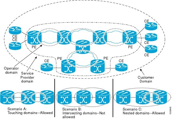
                                        A unique maintenance level in the range of 0 to 7 is assigned to each maintenance domain by a network administrator. Maintenance levels and domain names are useful for defining the hierarchical relationship that exists among domains. The hierarchical relationship of domains parallels the structure of customer, service provider, and operator. The higher the domain level, the broader the scope of the domain. For example, a customer domain would be larger than an operator domain. The customer domain may have a maintenance level of 7 and the operator domain may have a maintenance level of 0. Typically, operators would have the smallest domains and customers the largest domains, with service provider domains in between these domains, varying in size. All levels of the hierarchy must operate together.

                                        Domains must not intersect because intersecting would mean management by more than one entity, which is not allowed. Domains may nest or touch but when two domains nest, the outer domain must have a higher maintenance level than the domain nested within it. Nesting maintenance domains is useful in the business model where a service provider contracts with one or more operators to provide Ethernet service to a customer. Each operator would have its own maintenance domain and the service provider would define its domain that is a superset of the operator domains. Furthermore, the customer has its own end-to-end domain, which is in turn is a superset of the service provider domain. Maintenance levels of various nesting domains must be communicated among the administering organizations. For example, one approach would be to have the service provider assign maintenance levels to operators.

                                        The following characteristics of maintenance domains are supported:

                                        • Maintenance domains are identified by a unique domain name that can be up to 154 characters.

                                        • The domain name as null is supported; the maintenance association name is used as the identifier.

                                        • Domain configuration is not required for devices that have only Maintenance Intermediate Points (MIPs).

                                        • Mix of Up (toward the bridge) and Down (toward the wire) Maintenance Association End Points (MEPs) is supported.

                                        A domain can be removed when all the maintenance points within the domain have been removed and all the remote MEPs entries in the continuity check database (CCDB) for the domain have been purged.

                                        The following figure illustrates a hierarchy of operator, service provider, and customer domains and also illustrates touching, intersecting, and nested domains.

                                        DLP-J309 Create a Maintenance Domain Using Cisco IOS Commands

                                        Purpose This procedure creates a maintenance domain using Cisco IOS commands.
                                        Tools/Equipment None
                                        Prerequisite Procedures None
                                        Required/As Needed As needed
                                        Onsite/Remote Onsite or remote
                                        Security Level Provisioning or higher
                                        Procedure
                                           Command or ActionPurpose
                                          Step 1enable


                                          Example:Router> enable 

                                          Enables privileged EXEC mode.

                                          • Enter your password if prompted.

                                           
                                          Step 2configure terminal


                                          Example:Router# configure terminal 

                                          Enters global configuration mode.

                                           
                                          Step 3ethernet cfm domain domain-name level level-id


                                          Example:Router(config)# ethernet cfm domain customer level 7 

                                          Creates a CFM maintenance domain at a specific maintenance level and enters Ethernet CFM configuration mode. The range of the maintenance domain level is from 0 to 7.

                                          Note    You can create several maintenance domains at the same maintenance level. However, you cannot create a maintenance domain at several maintenance levels.
                                           
                                          Step 4end


                                          Example:Router(config)# end 

                                          Returns to privileged EXEC mode.

                                           
                                          Step 5Return to your originating procedure (NTP). 


                                          Example: Create a Maintenance Domain

                                          The following example shows how to define a domain named domain1 at level 6 and enters Ethernet CFM configuration mode:

                                          Router> enable
                                          Router# configure terminal
                                          Router(config)# ethernet cfm domain domain1 level 6
                                          Router(config-ecfm)#
                                          

                                          DLP-J301 Create and Modify a Maintenance Domain Profile Using CTC

                                          Purpose This procedure creates or modifies a maintenance domain profile using CTC.
                                          Tools/Equipment None
                                          Prerequisite Procedures None
                                          Required/As Needed As needed
                                          Onsite/Remote Onsite or remote
                                          Security Level Provisioning or higher
                                          Procedure
                                            Step 1   Complete the NTP-J22 Log into CTC procedure at a node where you want to create or modify a maintenance domain profile.
                                            Step 2   Right-click the fabric or line card and choose Open Packet Transport System View. The Packet Transport System View dialog box appears.
                                            Step 3   Click the Provisioning tab.
                                            Step 4   In the left pane, click CFM.
                                            Step 5   Click the Domain Profiles tab.
                                            Step 6   Click Add row(s).
                                            Step 7   Enter the name of the domain in the Domain Name field.
                                            Step 8   Enter the level of the domain profile in the Level field. The domain profile level ranges from 0 to 7.
                                            Step 9   Check the Sender Id check box to include the contents of the Sender ID time-length-value (TLV) field transmitted in CFM messages for members of a maintenance domain.
                                            Step 10   Check the Auto Create MIP check box to allow the automatic creation of an MIP at this maintenance domain level.
                                            Step 11   Check the Lower MEP check box. When this check box and Auto Create MIP check box are checked, auto MIPs are created at a specified level only where an MEP is configured at the next lower level for a maintenance domain.
                                            Step 12   Enter a value in the Archive Hold Timer field to specify the number of minutes that data from a missing MEP is kept before it is purged. The default value is 100 minutes. The range is from 1 to 65535 minutes.
                                            Step 13   Click Store.
                                            Step 14   In the CFM Profile Storing dialog box, choose the node and shelf where you want to store this domain profile and click OK.
                                            Step 15   To modify a maintenance domain profile, double-click the required parameters, change the values, and click Apply.
                                            Step 16   Return to your originating procedure (NTP).

                                            DLP-J302 Delete a Maintenance Domain Profile Using CTC

                                            Purpose This procedure deletes a maintenance domain profile using CTC.
                                            Tools/Equipment None
                                            Prerequisite Procedures None
                                            Required/As Needed As needed
                                            Onsite/Remote Onsite or remote
                                            Security Level Provisioning or higher
                                            Procedure
                                              Step 1   Complete the NTP-J22 Log into CTC procedure at a node where you want to delete a maintenance domain profile.
                                              Step 2   Right-click the fabric or line card and choose Open Packet Transport System View. The Packet Transport System View dialog box appears.
                                              Step 3   Click the Provisioning tab.
                                              Step 4   In the left pane, click CFM.
                                              Step 5   Click the Domain Profiles tab.
                                              Step 6   Click Load to load the maintenance domain profiles from the system. The CFM Profile Loading dialog box appears.
                                              Step 7   Choose the shelf and click OK. The domain profiles appear in the Domain Profiles tab.
                                              Step 8   Choose a domain profile to delete.
                                              Step 9   Check the On Node check box.
                                              Step 10   Click Delete Sel row(s). The CFM Profile Deleting dialog box appears.
                                              Step 11   Choose the shelf to delete the domain profile from and click OK.
                                              Step 12   Click Yes in the confirmation dialog box.
                                              Step 13   Return to your originating procedure (NTP).

                                              Understanding Maintenance Association

                                              There can be any number of maintenance associations (MA) within a maintenance domain. A maintenance association identifies a service that can be uniquely identified within the maintenance domains. The CFM protocol runs within a specific maintenance association.

                                              The MA direction is specified when the MA is configured. The MA name must be configured on a domain before MEPs can be configured. Configuring an MA is not required for devices that have only MIPs.

                                              DLP-J334 Create a Maintenance Association Using Cisco IOS Commands

                                              Purpose This procedure creates a maintenance association using Cisco IOS commands.
                                              Tools/Equipment None
                                              Prerequisite Procedures None
                                              Required/As Needed As needed
                                              Onsite/Remote Onsite or remote
                                              Security Level Provisioning or higher
                                              Procedure
                                                 Command or ActionPurpose
                                                Step 1enable


                                                Example:Router> enable 

                                                Enables privileged EXEC mode.

                                                • Enter your password if prompted.

                                                 
                                                Step 2configure terminal


                                                Example:Router# configure terminal 

                                                Enters global configuration mode.

                                                 
                                                Step 3ethernet cfm domain domain-name level level-id


                                                Example:Router(config)# ethernet cfm domain Customer level 7 

                                                Creates a maintenance domain at a specified level and enters Ethernet CFM configuration mode.

                                                 
                                                Step 4service {ma-name | number ma-num} {evc evc-name | port } [direction down]

                                                Example:Router(config-ecfm)# service Customer1 port 

                                                Creates a maintenance association within a maintenance domain and enters CFM service configuration mode.

                                                 
                                                Step 5exit


                                                Example:Router(config-ecfm)# exit 

                                                Returns to global configuration mode.

                                                 
                                                Step 6Return to your originating procedure (NTP). 


                                                Example: Create a Maintenance Association

                                                The following example shows how to create a maintenance association using Cisco IOS commands:

                                                Router> enable
                                                Router# configure terminal
                                                Router(config)# ethernet cfm domain operator level 5
                                                Router(config-ecfm)# service operatorA port
                                                Router(config-ecfm)# exit
                                                

                                                DLP-J333 Configure CFM Encapsulation Using Cisco IOS Commands

                                                Purpose This procedure configures CFM encapsulation using Cisco IOS commands.
                                                Tools/Equipment None
                                                Prerequisite Procedures None
                                                Required/As Needed As needed
                                                Onsite/Remote Onsite or remote
                                                Security Level Provisioning or higher
                                                Procedure
                                                   Command or ActionPurpose
                                                  Step 1enable


                                                  Example:Router> enable 

                                                  Enables privileged EXEC mode.

                                                  • Enter your password if prompted.

                                                   
                                                  Step 2configure terminal


                                                  Example:Router# configure terminal 

                                                  Enters global configuration mode.

                                                   
                                                  Step 3interface type number


                                                  Example:Router(config)# interface TenGigabitEthernet 4/1 

                                                  Specifies the interface to configure and enters interface configuration mode.

                                                   
                                                  Step 4service instance id ethernet [evc-id]


                                                  Example:Router(config-if)# service instance 101 ethernet 

                                                  Configures an Ethernet service instance on an interface and enters service instance configuration mode.

                                                   
                                                  Step 5encapsulation dot1q {any | vlan-id [vlan-id [-vlan-id]]} second-dot1q {any | vlan-id [vlan-id [-vlan-id]]}

                                                  Example:Router(config-if-srv)# encapsulation dot1q 100-110 second dot1q 200 

                                                  Defines the matching criteria that maps the ingress dot1q, QinQ, or untagged frames on an interface to the appropriate service instance.

                                                   
                                                  Step 6bridge-domain bridge-id [split-horizon ]


                                                  Example:Router(config-if-srv)# bridge-domain 12  

                                                  Binds the Ethernet service instance to a bridge domain instance where bridge-id is the identifier for the bridge domain instance.

                                                   
                                                  Step 7cfm encapsulation {dot1ad vlan-id | dot1q vlan-id} [dot1q vlan-id | second-dot1q vlan-id]

                                                  Example:Router(config-if-srv)# cfm encapsulation dot1q 105 second dot1q 200 

                                                  Defines the matching criteria that maps the ingress dot1q, QinQ, or untagged frames on an interface to the appropriate service instance.

                                                   
                                                  Step 8exit


                                                  Example:Router(config-if-srv)# exit 

                                                  Exits the service instance configuration mode.

                                                   
                                                  Step 9exit


                                                  Example:Router(config-if)# exit 

                                                  Returns to global configuration mode.

                                                   
                                                  Step 10end


                                                  Example:Router(config)# end 

                                                  Returns to privileged EXEC mode.

                                                   
                                                  Step 11Return to your originating procedure (NTP). 


                                                  DLP-J303 Create and Modify a Maintenance Association Profile Using CTC

                                                  Purpose This procedure creates or modifies a maintenance association profile using CTC.
                                                  Tools/Equipment None
                                                  Prerequisite Procedures None
                                                  Required/As Needed As needed
                                                  Onsite/Remote Onsite or remote
                                                  Security Level Provisioning or higher
                                                  Procedure
                                                    Step 1   Complete the NTP-J22 Log into CTC procedure at a node where you want to create or modify a maintenance association profile.
                                                    Step 2   Right-click the fabric or line card and choose Open Packet Transport System View. The Packet Transport System View dialog box appears.
                                                    Step 3   Click the Provisioning tab.
                                                    Step 4   In the left pane, click CFM.
                                                    Step 5   Click the MA Profiles tab.
                                                    Step 6   Click Add row(s).
                                                    Step 7   Enter the name of the maintenance association profile in the Maintenance Profile Name field.
                                                    Step 8   Enter the unique ID used to represent a service in the Service ID field.

                                                    Service IDs identify customers within a domain. A service ID must be unique within a single maintenance domain.

                                                    Step 9   Check the CC Enable check box to globally enable transmission of Continuity Check Messages (CCMs).
                                                    Step 10   From the CC Interval drop-down list, choose the interval to transmit CCMs.

                                                    The valid values are as follows:

                                                    • 100 ms—100 milliseconds

                                                    • 1 sec—1 second

                                                    • 10 sec—10 seconds

                                                    • 1 min—1 minute

                                                    • 10 min—10 minutes

                                                    Step 11   Enter the number of CCMs that must be missed before declaring that a remote MEP is down, in the CC Threshold field.

                                                    The range is from 2 to 255. The default value is 3.

                                                    Step 12   Check the Direction Down check box to configure the service direction toward the LAN.
                                                    Step 13   Enter the maintenance domain name in the Domain Name field to attach this maintenance association profile to a maintenance domain profile.
                                                    Step 14   Check the Auto Create MIP check box to dynamically create an MIP.
                                                    Step 15   Check the Port check box to create a port MEP.
                                                    Step 16   Check the Lower MEP Only check box. When this check box and Auto Create MIP check box are checked, auto MIPs are created at a specified level only where an MEP is configured at the next lower level for a maintenance domain.
                                                    Step 17   Check the CFM EFM Interaction check box to enable the CFM and EFM protocols to interoperate.

                                                    CFM and EFM can interoperate together and can co-exist on the same port. CFM and EFM cannot interoperate together if CFM MEP is configured on the channel group. Use the oam protocol cfm domain domain-name to configure CFM and EFM to interoperate together using Cisco IOS commands.

                                                    Step 18   Enter the static MEP ID or a list of static MEP IDs in the Static MEP Id field to statically specify the MEP IDs. The range is from 1 to 8191.
                                                    Step 19   Check the MEP Cross Check Enable check box to enable cross-checking between the list of configured remote MEPs of a domain and MEPs learned through CCMs.
                                                    Step 20   Enter the outer dot1q encapsulation tag value in the Outer CFM Encapsulation field.
                                                    Step 21   Enter the inner dot1q encapsulation tag value in the Inner CFM Encapsulation field.
                                                    Step 22   Click Store.
                                                    Step 23   Choose the node and shelf where you want to store this maintenance association profile and click OK.
                                                    Step 24   To modify a maintenance association profile, double-click the required parameters, change the values, and click Apply.
                                                    Step 25   Return to your originating procedure (NTP).

                                                    DLP-J304 Delete a Maintenance Association Profile Using CTC

                                                    Purpose This procedure deletes a maintenance association profile using CTC.
                                                    Tools/Equipment None
                                                    Prerequisite Procedures None
                                                    Required/As Needed As needed
                                                    Onsite/Remote Onsite or remote
                                                    Security Level Provisioning or higher
                                                    Procedure
                                                      Step 1   Complete the NTP-J22 Log into CTC procedure at a node where you want to delete a maintenance association profile.
                                                      Step 2   Right-click the fabric or line card and choose Open Packet Transport System View. The Packet Transport System View dialog box appears.
                                                      Step 3   Click the Provisioning tab.
                                                      Step 4   In the left pane, click CFM.
                                                      Step 5   Click the MA Profiles tab.
                                                      Step 6   Click Load to load the maintenance association profiles from the system. The CFM Profile Loading dialog box appears.
                                                      Step 7   Choose the shelf and click OK. The maintenance association profiles appear in the MA Profiles tab.
                                                      Step 8   Choose an association profile to delete.
                                                      Step 9   Check the On Node check box.
                                                      Step 10   Click Delete Sel row(s). The CFM Profile Deleting dialog box appears.
                                                      Step 11   Choose the shelf to delete the association profile from and click OK.
                                                      Step 12   Click Yes in the confirmation dialog box.
                                                      Step 13   Return to your originating procedure (NTP).

                                                      Understanding Maintenance Point

                                                      Any port of a bridge is referred to as a Maintenance Point. A maintenance point is a demarcation point on an interface or port that participates in CFM within a maintenance domain. Maintenance points must be explicitly configured on Cisco devices.

                                                      There are two classes of maintenance points:

                                                      • Maintenance End Points (MEPs)

                                                      • Maintenance Intermediate Points (MIPs)

                                                      Understanding Maintenance End Points

                                                      MEPs reside at the edge of a maintenance domain and are active elements of CFM. They confine CFM messages within the domain through the maintenance domain level. MEPs periodically transmit and receive continuity check messages (CCMs) from other MEPs within the domain. MEPs also transmit linktrace and loopback messages at the request of the administrator.

                                                      MEP ID uniquely identifies each MEP along with those configured on a single MA. The MEP IDs range from 1 to 8191.

                                                      There are two types of MEPs:

                                                      • Up (inwards, toward the bridge). This is the default.

                                                      • Down (outwards, toward the wire).

                                                      MEP supports multicast loopbacks and pings. When a multicast ping is initiated for a particular domain or service, all the related remote MEPs reply to the ping.

                                                      MEP configurations can be removed after all pending loopback and linktrace replies are removed and the service on the interface is set to transparent mode. To set the service to transparent mode, MIP filtering must not be configured.

                                                      Understanding Up MEPs

                                                      An Up MEP is an MEP that resides in a bridge and transmits to and receives CFM messages from the direction of the bridge relay entity.

                                                      An Up MEP performs the following functions:

                                                      • Sends and receives CFM frames at its level through the bridge relay and not through the wire connected to the port on which the MEP is configured.

                                                      • Drops all CFM frames at its level (or lower level) that come from the direction of the wire.

                                                      • Processes all CFM frames at its level coming from the direction of the bridge.

                                                      • Drops all CFM frames at a lower level coming from the direction of the bridge.

                                                      • Forwards all CFM frames transparently at a higher level, independent of whether they came in from the bridge or wire.

                                                      Understanding Down MEPs

                                                      A Down MEP is an MEP that resides in a bridge and transmits to and receives CFM messages from the direction of the wire.

                                                      A Down MEP performs the following functions:

                                                      • Sends and receives CFM frames at its level through the wire connected to the port where the MEP is configured.

                                                      • Drops all CFM frames at its level (or at a lower level) that come from the direction of the bridge.

                                                      • Processes all CFM frames at its level coming from the direction of the wire.

                                                      • Drops all CFM frames at a lower level coming from the direction of the wire.

                                                      • Forwards all CFM frames transparently at a higher level, independent of whether they came in from the bridge or wire.

                                                      Understanding Port MEPs

                                                      CPT also supports Port MEP at the physical port. A port MEP can be created either on the physical port or on the port of a channel group. The port MEP takes higher precedence if both the port MEP and the Down MEP on untagged EFP is created on the same port.

                                                      Understanding the Cross-Check Function

                                                      The cross-check function is a timer-driven post-provisioning service verification between dynamically discovered MEPs (through CCMs) and expected MEPs (through configuration) for a service. The cross-check function verifies that all the endpoints of a multipoint or point-to-point service are operational. The function supports notifications when the service is operational; otherwise it provides alarms and notifications for unexpected or missing endpoints.

                                                      You must initiate the cross-check function each time you want a service verification. See DLP-J323 Configure Cross-Check for an MEP Using Cisco IOS Commands.

                                                      DLP-J310 Create a Port MEP Using Cisco IOS Commands

                                                      Purpose This procedure creates a port MEP using Cisco IOS commands.
                                                      Tools/Equipment None
                                                      Prerequisite Procedures None
                                                      Required/As Needed As needed
                                                      Onsite/Remote Onsite or remote
                                                      Security Level Provisioning or higher
                                                      Procedure
                                                         Command or ActionPurpose
                                                        Step 1enable


                                                        Example:Router> enable 

                                                        Enables privileged EXEC mode.

                                                        • Enter your password if prompted.

                                                         
                                                        Step 2configure terminal


                                                        Example:Router# configure terminal 

                                                        Enters global configuration mode.

                                                         
                                                        Step 3interface type number


                                                        Example:Router(config)# interface TenGigabitEthernet 4/1 

                                                        Specifies the interface to configure and enters interface configuration mode.

                                                         
                                                        Step 4ethernet cfm mep domain domain-name mpid mpid {port}


                                                        Example:Router(config-if)# ethernet cfm mep domain Customer mpid 701 port 

                                                        Sets a port as internal to a maintenance domain and creates a port MEP. A port MEP can be created only on a physical port or on a port of a channel group.

                                                         
                                                        Step 5exit


                                                        Example:Router(config-if)# exit 

                                                        Returns to global configuration mode.

                                                         
                                                        Step 6end


                                                        Example:Router(config)# end 

                                                        Returns to privileged EXEC mode.

                                                         
                                                        Step 7Return to your originating procedure (NTP). 


                                                        Example: Create a Port MEP

                                                        The following example shows how to set a port as internal to a maintenance domain and creates a port MEP:

                                                        Router> enable
                                                        Router# configure terminal
                                                        Router(config)# interface TenGigabitEthernet 4/1
                                                        Router(config-if)# ethernet cfm mep domain CustomerB mpid 5 port
                                                        

                                                        DLP-J321 Create an MEP for an EFP Using Cisco IOS Commands

                                                        Purpose This procedure creates an MEP for an EFP using Cisco IOS commands.
                                                        Tools/Equipment None
                                                        Prerequisite Procedures None
                                                        Required/As Needed As needed
                                                        Onsite/Remote Onsite or remote
                                                        Security Level Provisioning or higher
                                                        Procedure
                                                           Command or ActionPurpose
                                                          Step 1enable


                                                          Example:Router> enable 

                                                          Enables privileged EXEC mode.

                                                          • Enter your password if prompted.

                                                           
                                                          Step 2configure terminal


                                                          Example:Router# configure terminal 

                                                          Enters global configuration mode.

                                                           
                                                          Step 3interface type number


                                                          Example:Router(config)# interface TenGigabitEthernet 4/1 

                                                          Specifies the interface to configure and enters interface configuration mode.

                                                           
                                                          Step 4service instance id ethernet [evc-id]


                                                          Example:Router(config-if)# service instance 101 ethernet 

                                                          Configures an Ethernet service instance on an interface and enters service instance configuration mode.

                                                           
                                                          Step 5encapsulation dot1q {any | vlan-id [vlan-id [-vlan-id]]} second-dot1q {any | vlan-id [vlan-id [-vlan-id]]}

                                                          Example:Router(config-if-srv)# encapsulation dot1q 100 second dot1q 200 

                                                          Defines the matching criteria that maps the ingress dot1q, QinQ, or untagged frames on an interface to the appropriate service instance.

                                                           
                                                          Step 6bridge-domain bridge-id [split-horizon ]


                                                          Example:Router(config-if-srv)# bridge-domain 12  

                                                          Binds the Ethernet service instance to a bridge domain instance where bridge-id is the identifier for the bridge domain instance.

                                                           
                                                          Step 7cfm mep domain domain-name mpid mpid-value


                                                          Example:Router(config-if-srv)# cfm mep domain Customer mpid 701 

                                                          Creates an MEP under the Ethernet service instance.

                                                           
                                                          Step 8exit


                                                          Example:Router(config-if-srv)# exit 

                                                          Exits the service instance configuration mode.

                                                           
                                                          Step 9exit


                                                          Example:Router(config-if)# exit 

                                                          Returns to global configuration mode.

                                                           
                                                          Step 10end


                                                          Example:Router(config)# end 

                                                          Returns to privileged EXEC mode.

                                                           
                                                          Step 11Return to your originating procedure (NTP). 


                                                          Example: Create an MEP for an EFP

                                                          The following example shows how to create an MEP for an EFP using Cisco IOS commands:

                                                          Router> enable
                                                          Router# configure terminal
                                                          Router(config)# interface TenGigabitEthernet 4/1
                                                          Router(config-if)# service instance 101 ethernet
                                                          Router(config-if-srv)# encapsulation  dot1q 100
                                                          Router(config-if-srv)# bridge-domain 12 
                                                          Router(config-if-srv)# cfm mep domain CustomerB mpid 5 
                                                          Router(config-if-srv)# exit
                                                          

                                                          DLP-J319 Define MEPs Statically within a Maintenance Association Using Cisco IOS Commands

                                                          Purpose This procedure statically defines MEPs within a maintenance association using Cisco IOS commands.
                                                          Tools/Equipment None
                                                          Prerequisite Procedures None
                                                          Required/As Needed As needed
                                                          Onsite/Remote Onsite or remote
                                                          Security Level Provisioning or higher
                                                          Procedure
                                                             Command or ActionPurpose
                                                            Step 1enable


                                                            Example:Router> enable 

                                                            Enables privileged EXEC mode.

                                                            • Enter your password if prompted.

                                                             
                                                            Step 2configure terminal


                                                            Example:Router# configure terminal 

                                                            Enters global configuration mode.

                                                             
                                                            Step 3ethernet cfm domain domain-name level level-id


                                                            Example:Router(config)# ethernet cfm domain Customer level 7 

                                                            Defines a CFM domain at a specified level and enters Ethernet CFM configuration mode. The range of maintenance domain level is from 0 to 7.

                                                             
                                                            Step 4service {ma-name | number ma-num} {evc evc-name | port } [direction down]

                                                            Example:Router(config-ecfm)# service Customer1 port 

                                                            Configures a maintenance association within a maintenance domain for a port MEP or MEP for an EFP and enters CFM service configuration mode.

                                                             
                                                            Step 5mep mpid mpid


                                                            Example:Router(config-ecfm-srv)# mep mpid 702 

                                                            Statically defines the MEPs within a maintenance association.

                                                             
                                                            Step 6exit


                                                            Example:Router(config-ecfm-srv)# exit 

                                                            Returns to Ethernet CFM configuration mode.

                                                             
                                                            Step 7exit


                                                            Example:Router(config-ecfm)# exit 

                                                            Returns to global configuration mode.

                                                             
                                                            Step 8Return to your originating procedure (NTP). 


                                                            Example: Define the MEPs Statically within a Maintenance Association

                                                            The following example shows how to configure an MEP with an ID of 25 using Cisco IOS commands:

                                                            Router> enable
                                                            Router# configure terminal
                                                            Router(config)# ethernet cfm domain operator level 5
                                                            Router(config-ecfm)# service operatorA port
                                                            Router(config-ecfm-srv)# mep mpid 25
                                                            Router(config-ecfm-srv)# exit
                                                            Router(config-ecfm)# exit
                                                            

                                                            DLP-J318 Specify the Number of MEPs in a Maintenance Association Using Cisco IOS Commands

                                                            Purpose This procedure allows you to specify the number of MEPs in a maintenance association using Cisco IOS commands.
                                                            Tools/Equipment None
                                                            Prerequisite Procedures None
                                                            Required/As Needed As needed
                                                            Onsite/Remote Onsite or remote
                                                            Security Level Provisioning or higher
                                                            Procedure
                                                               Command or ActionPurpose
                                                              Step 1enable


                                                              Example:Router> enable 

                                                              Enables privileged EXEC mode.

                                                              • Enter your password if prompted.

                                                               
                                                              Step 2configure terminal


                                                              Example:Router# configure terminal 

                                                              Enters global configuration mode.

                                                               
                                                              Step 3ethernet cfm domain domain-name level level-id


                                                              Example:Router(config)# ethernet cfm domain Customer level 7 

                                                              Defines a CFM domain at a specified level and enters Ethernet CFM configuration mode. The range of maintenance domain level is from 0 to 7.

                                                               
                                                              Step 4service {ma-name | number ma-num} {evc evc-name | port} [direction down]

                                                              Example:Router(config-ecfm)# service Customer1 port 

                                                              Configures a maintenance association within a maintenance domain for a port MEP or MEP for an EFP and enters CFM service configuration mode.

                                                               
                                                              Step 5maximum meps max-num


                                                              Example:Router(config-ecfm-srv)# maximum meps 50 

                                                              Specifies the maximum number of MEPs in a maintenance association. The default is 100. The range is from 1 to 65535.

                                                               
                                                              Step 6exit


                                                              Example:Router(config-ecfm-srv)# exit 

                                                              Returns the CLI to Ethernet CFM configuration mode.

                                                               
                                                              Step 7exit


                                                              Example:Router(config-ecfm)# exit 

                                                              Returns to global configuration mode.

                                                               
                                                              Step 8Return to your originating procedure (NTP). 


                                                              Example: Specify the Number of MEPs in a Maintenance Association

                                                              The following example shows how to configure a maximum of 50 MEPs using Cisco IOS commands:

                                                              Router> enable
                                                              Router# configure terminal
                                                              Router(config)# ethernet cfm domain operator level 5
                                                              Router(config-ecfm)# service operatorA port
                                                              Router(config-ecfm-srv)# maximum meps 50
                                                              Router(config-ecfm-srv)# exit
                                                              Router(config-ecfm)# exit
                                                              

                                                              DLP-J323 Configure Cross-Check for an MEP Using Cisco IOS Commands

                                                              Purpose This procedure configures cross-checking for an MEP using Cisco IOS commands.
                                                              Tools/Equipment None
                                                              Prerequisite Procedures None
                                                              Required/As Needed As needed
                                                              Onsite/Remote Onsite or remote
                                                              Security Level Provisioning or higher
                                                              Procedure
                                                                 Command or ActionPurpose
                                                                Step 1enable


                                                                Example:Router> enable 

                                                                Enables privileged EXEC mode.

                                                                • Enter your password if prompted.

                                                                 
                                                                Step 2configure terminal


                                                                Example:Router# configure terminal 

                                                                Enters global configuration mode.

                                                                 
                                                                Step 3ethernet cfm domain domain-name level level-id


                                                                Example:Router(config)# ethernet cfm domain ServiceProvider level 4 

                                                                Creates a maintenance domain at a specified level and enters Ethernet CFM configuration mode. The range of maintenance domain level is from 0 to 7.

                                                                 
                                                                Step 4service {ma-name | number ma-num} {evc evc-name | port } [direction down]

                                                                Example:Router(config-ecfm)# service Customer1 port 

                                                                Configures a maintenance association within a maintenance domain and enters CFM service configuration mode.

                                                                 
                                                                Step 5mep mpid mpid


                                                                Example:Router(config-ecfm-srv)# mep mpid 702 

                                                                Statically defines the MEPs within a maintenance association.

                                                                 
                                                                Step 6exit


                                                                Example:Router(config-ecfm-srv)# exit 

                                                                Returns to Ethernet CFM configuration mode.

                                                                 
                                                                Step 7exit


                                                                Example:Router(config-ecfm)# exit 

                                                                Returns to global configuration mode.

                                                                 
                                                                Step 8ethernet cfm mep crosscheck start-delay delay


                                                                Example:Router(config)# ethernet cfm mep crosscheck start-delay 60 

                                                                Configures the maximum amount of time that the device waits for remote MEPs to come up before the cross-check operation is started. The default value is 30 seconds. The range is from 1 to 65535 seconds.

                                                                 
                                                                Step 9exit


                                                                Example:Router(config)# exit 

                                                                Returns to privileged EXEC mode.

                                                                 
                                                                Step 10ethernet cfm mep crosscheck {enable | disable} domain domain-name port

                                                                Example:Router# ethernet cfm mep crosscheck enable domain cust4 port 

                                                                Enables cross-checking between the list of configured remote MEPs of a domain and MEPs learned through CCMs.

                                                                 
                                                                Step 11Return to your originating procedure (NTP). 


                                                                DLP-J306 Create an MEP Using CTC

                                                                Purpose This procedure creates a maintenance end point using CTC.
                                                                Tools/Equipment None
                                                                Prerequisite Procedures None
                                                                Required/As Needed As needed
                                                                Onsite/Remote Onsite or remote
                                                                Security Level Provisioning or higher
                                                                Procedure
                                                                  Step 1   Complete the NTP-J22 Log into CTC procedure at a node where you want to create a maintenance end point.
                                                                  Step 2   Right-click the fabric or line card and choose Open Packet Transport System View. The Packet Transport System View dialog box appears.
                                                                  Step 3   Click the Provisioning tab.
                                                                  Step 4   In the left pane, click CFM.
                                                                  Step 5   Click the MEP tab.
                                                                  Step 6   Click Create. The Create MEP dialog box appears.
                                                                  Step 7   To create an MEP on an EFP:
                                                                  1. Choose the Service Id option.
                                                                  2. From the Domain drop-down list, choose a maintenance domain.
                                                                  3. Enter the service id in the Service ID field.
                                                                  4. Enter the maintenance point ID (MPID) in the MPID field.

                                                                    The MPID ranges from 1 to 8191. The MPID must not be the same between the maintenance end points.

                                                                  5. Enter the class-of-service (CoS) for CFM packets in the COS field.

                                                                    The range of CoS is from 0 to 7.

                                                                  Step 8   To create an MEP on a port:
                                                                  Note    A port MEP can be created only on a physical port or on a port of a channel group.
                                                                  1. Choose the Port option.
                                                                  2. From the Slot drop-down list, choose a fabric card or a line card slot.
                                                                  3. From the Port drop-down list, choose a port.
                                                                  4. From the Domain drop-down list, choose a maintenance domain.
                                                                  5. Enter the maintenance point ID (MPID) in the MPID field.

                                                                    The MPID ranges from 1 to 8191. The MPID must not be the same between the maintenance end points.

                                                                  6. Enter the class-of-service (CoS) for CFM packets in the COS field.

                                                                    The range of CoS is from 0 to 7.

                                                                  Step 9   To create an MEP on a channel group:
                                                                  1. Check the MEP on Ch.Grp check box.
                                                                  2. From the Domain drop-down list, choose a maintenance domain.
                                                                  3. Enter the service id in the Service ID field.
                                                                  4. Enter the maintenance point ID (MPID) in the MPID field.

                                                                    The MPID ranges from 1 to 8191. The MPID must not be the same between the maintenance end points.

                                                                  5. Enter the class-of-service (CoS) for CFM packets in the COS field.

                                                                    The range of CoS is from 0 to 7.

                                                                  6. From the Ch Grp drop-down list, choose a channel group.
                                                                  Step 10   Click OK in the Create MEP dialog box to create an MEP.
                                                                  Step 11   To delete an MEP:
                                                                  1. Choose an MEP to delete in the MEP tab.
                                                                  2. Click Delete.
                                                                  3. Click Yes in the Delete MEP dialog box.
                                                                  Step 12   Return to your originating procedure (NTP).

                                                                  Understanding Maintenance Intermediate Points

                                                                  Maintenance intermediate points (MIPs) are internal to the maintenance domain and are passive elements of CFM. They store information received from MEPs and other MIPs and respond only to CFM linktrace and loopback messages. An MIP has only one level associated with it. MIPs forward CFM messages within a maintenance domain.

                                                                  MIPs are defined as two MIP half functions (MHFs)—An Up MHF that resides above the port filtering entities and a Down MHF that resides below the port filtering entities. The same configuration parameters and characteristics apply to both MHFs of an MIP:

                                                                  • Can be created manually or dynamically (auto MIPs).

                                                                  • Dynamically created depending on configured policies at managed objects (MA, maintenance domain, or the default domain level).

                                                                  • Manual MIPs can be created under an interface and under a service instance within an interface.

                                                                  • Auto MIP commands can be issued globally or under a domain or service.

                                                                  • Can be created per MA, which means that an MIP in the MA can be lower level than an MEP in another MA.

                                                                  • CFM frames received from MEPs and other MIPs are cataloged and forwarded, using both the wire and the bridge relay.

                                                                  • When MIP filtering is enabled, all CFM frames at a lower level are stopped and dropped, independent of whether they originate from the wire or the bridge relay.

                                                                  • All CFM frames at a higher level are forwarded, independent of whether they arrive from the wire or from the bridge relay.

                                                                  • Passive points respond only when triggered by CFM linktrace and loopback messages.

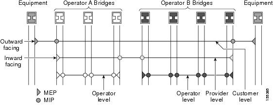
                                                                  The following figure illustrates MEPs and MIPs at the operator, service provider, and customer levels.

                                                                  DLP-J311 Create an MIP Dynamically Using Cisco IOS Commands

                                                                  Purpose This procedure creates an MIP dynamically using Cisco IOS commands.
                                                                  Tools/Equipment None
                                                                  Prerequisite Procedures None
                                                                  Required/As Needed As needed
                                                                  Onsite/Remote Onsite or remote
                                                                  Security Level Provisioning or higher

                                                                  Note


                                                                  ethernet cfm mip auto-create command has lower precedence than the ethernet cfm mip level manual MIP command. For example, if you manually configure an MIP for a particular maintenance association, that configuration overrides the MIP created by the global ethernet cfm mip auto-create command for that maintenance association.


                                                                  Procedure
                                                                     Command or ActionPurpose
                                                                    Step 1enable


                                                                    Example:Router> enable 

                                                                    Enables privileged EXEC mode.

                                                                    • Enter your password if prompted.

                                                                     
                                                                    Step 2configure terminal


                                                                    Example:Router# configure terminal 

                                                                    Enters global configuration mode.

                                                                     
                                                                    Step 3ethernet cfm mip {auto-create level level-id [lower-mep-only] [sender-id chassis] | filter}


                                                                    Example:Router(config)# ethernet cfm mip auto-create level 1 

                                                                    Dynamically creates an MIP and provisions it globally at a specified maintenance level and enables level filtering.

                                                                     
                                                                    Step 4end


                                                                    Example:Router(config)# end 

                                                                    Returns to privileged EXEC mode.

                                                                     
                                                                    Step 5Return to your originating procedure (NTP). 


                                                                    Example: Create an MIP Dynamically

                                                                    The following example shows how to dynamically create an MIP at maintenance level 6 using Cisco IOS commands:

                                                                    Router> enable
                                                                    Router# configure terminal
                                                                    Router(config)# ethernet cfm mip auto-create level 6
                                                                    

                                                                    DLP-J322 Create an MIP Manually Using Cisco IOS Commands

                                                                    Purpose This procedure creates an MIP manually using Cisco IOS commands.
                                                                    Tools/Equipment None
                                                                    Prerequisite Procedures None
                                                                    Required/As Needed As needed
                                                                    Onsite/Remote Onsite or remote
                                                                    Security Level Provisioning or higher

                                                                    Note


                                                                    You cannot configure an MIP at a level lower than the level of already configured maintenance endpoints (MEPs) on an interface. Configuring an MIP using this command is known as a manual MIP and has precedence over the ethernet cfm mip auto-create command.


                                                                    Procedure
                                                                       Command or ActionPurpose
                                                                      Step 1enable


                                                                      Example:Router> enable 

                                                                      Enables privileged EXEC mode.

                                                                      • Enter your password if prompted.

                                                                       
                                                                      Step 2configure terminal


                                                                      Example:Router# configure terminal 

                                                                      Enters global configuration mode.

                                                                       
                                                                      Step 3interface type number


                                                                      Example:Router(config)# interface TenGigabitEthernet 4/1 

                                                                      Specifies the interface to configure and enters interface configuration mode.

                                                                       
                                                                      Step 4ethernet cfm mip level level-id


                                                                      Example:Router(config-if)# ethernet cfm mip level 1 

                                                                      Creates an MIP manually at a specified maintenance level on an interface. The range of level is from 0 to 7.

                                                                       
                                                                      Step 5exit


                                                                      Example:Router(config-if)# exit 

                                                                      Returns to global configuration mode.

                                                                       
                                                                      Step 6end


                                                                      Example:Router(config)# end 

                                                                      Returns to privileged EXEC mode.

                                                                       
                                                                      Step 7Return to your originating procedure (NTP). 


                                                                      Example: Create an MIP Manually

                                                                      The following example shows how to provision an MIP manually at maintenance level 5 using Cisco IOS commands.

                                                                      Router> enable
                                                                      Router# configure terminal
                                                                      Router(config)# interface TenGigabitEthernet 4/1
                                                                      Router(config-if)# ethernet cfm mip level 5
                                                                      Router(config-if)# exit

                                                                      DLP-J307 Create an MIP Using CTC

                                                                      Purpose This procedure creates a maintenance intermediate point with a specific maintenance level using CTC.
                                                                      Tools/Equipment None
                                                                      Prerequisite Procedures None
                                                                      Required/As Needed As needed
                                                                      Onsite/Remote Onsite or remote
                                                                      Security Level Provisioning or higher
                                                                      Procedure
                                                                        Step 1   Complete the NTP-J22 Log into CTC procedure at a node where you want to create a maintenance intermediate point.
                                                                        Step 2   Right-click the fabric or line card and choose Open Packet Transport System View. The Packet Transport System View dialog box appears.
                                                                        Step 3   Click the Provisioning tab.
                                                                        Step 4   In the left pane, click CFM.
                                                                        Step 5   Click the MIP tab.
                                                                        Step 6   Click Create. The Create MIP dialog box appears.
                                                                        Step 7   To create an MIP on an EFP:
                                                                        1. Choose the service Id option.
                                                                        2. From the Slot drop-down list, choose a fabric card or a line card slot.
                                                                        3. From the Port drop-down list, choose a port.
                                                                        4. From the Level drop-down list, choose a maintenance level. The maintenance level ranges from 0 to 7.
                                                                        5. Enter the service id in the ServiceId field.
                                                                        Step 8   To create an MIP on a channel group:
                                                                        1. Check the MIP on Ch.Grp check box.
                                                                        2. From the Level drop-down list, choose a maintenance level. The maintenance level ranges from 0 to 7.
                                                                        3. Enter the service id in the ServiceId field.
                                                                        4. From the Ch Grp drop-down list, choose a channel group.
                                                                        Step 9   Click OK in the Create MIP dialog box to create an MIP.
                                                                        Step 10   To delete an MIP:
                                                                        1. Choose an MIP to delete in the MIP tab.
                                                                        2. Click Delete.
                                                                        3. Click Yes in the Delete MIP dialog box.
                                                                        Step 11   Return to your originating procedure (NTP).

                                                                        Understanding CFM Messages

                                                                        CFM uses standard Ethernet frames that can be distinguished by their EtherType and for multicast messages by their MAC address. CFM frames are sourced, terminated, processed, and relayed by bridges.

                                                                        Bridges that cannot interpret CFM messages forward them as normal data frames. All CFM messages are confined to a maintenance domain and to a maintenance association. Three types of messages are supported:

                                                                        • Continuity Check

                                                                        • Linktrace

                                                                        • Loopback

                                                                        Understanding Continuity Check Messages

                                                                        CFM continuity check messages (CCMs) are multicast heartbeat messages exchanged periodically among MEPs. They allow MEPs to discover other MEPs within a domain and allow MIPs to discover MEPs. CCMs are confined to a domain.

                                                                        CFM CCMs have the following characteristics:

                                                                        • Transmitted at a periodic interval by MEPs. The interval can be one of the following configurable values. The default is 10 seconds.

                                                                          • 100 milliseconds

                                                                          • 1 second

                                                                          • 10 seconds

                                                                          • 1 minute

                                                                          • 10 minutes

                                                                        • Cataloged by MIPs at the same maintenance level.

                                                                        • Terminated by remote MEPs at the same maintenance level.

                                                                        • Unidirectional and do not solicit a response.

                                                                        • Indicate the status of the bridge port on which the MEP is configured.

                                                                        DLP-J316 Enable the Transmission of Continuity Check Messages Using Cisco IOS Commands

                                                                        Purpose This procedure enables the transmission of continuity check messages (CCM) using Cisco IOS commands.
                                                                        Tools/Equipment None
                                                                        Prerequisite Procedures None
                                                                        Required/As Needed As needed
                                                                        Onsite/Remote Onsite or remote
                                                                        Security Level Provisioning or higher
                                                                        Procedure
                                                                           Command or ActionPurpose
                                                                          Step 1enable


                                                                          Example:Router> enable 

                                                                          Enables privileged EXEC mode.

                                                                          • Enter your password if prompted.

                                                                           
                                                                          Step 2configure terminal


                                                                          Example:Router# configure terminal 

                                                                          Enters global configuration mode.

                                                                           
                                                                          Step 3ethernet cfm domain domain-name level level-id


                                                                          Example:Router(config)# ethernet cfm domain Customer level 7 

                                                                          Creates a CFM maintenance domain at a specified maintenance level and enters Ethernet CFM configuration mode. The range of maintenance domain level is from 0 to 7.

                                                                           
                                                                          Step 4service {ma-name | number ma-num} {evc evc-nameport } [direction down]

                                                                          Example:Router(config-ecfm)# service Customer1 port 

                                                                          Configures a maintenance association within a maintenance domain for a port MEP or MEP for an EFP and enters CFM service configuration mode.

                                                                           
                                                                          Step 5continuity-check [interval time | loss-threshold threshold | static rmep]

                                                                          Example:Router(config-ecfm-srv)# continuity-check 

                                                                          Enables the transmission of CCMs.

                                                                           
                                                                          Step 6continuity-check [interval time | loss-threshold threshold | static rmep]

                                                                          Example:Router(config-ecfm-srv)# continuity-check interval 10s 

                                                                          Configures the time period between CCM transmissions.

                                                                           
                                                                          Step 7continuity-check [interval time | loss-threshold threshold | static rmep]

                                                                          Example:Router(config-ecfm-srv)# continuity-check lossthreshold 10 

                                                                          Sets the number of CCMs that must be missed before declaring that a remote MEP is down.

                                                                           
                                                                          Step 8exit


                                                                          Example:Router(config-ecfm-srv)# exit 

                                                                          Returns to Ethernet CFM configuration mode.

                                                                           
                                                                          Step 9mep archive-hold-time minutes


                                                                          Example:Router(config-ecfm)# mep archive-hold-time 60 

                                                                          Sets the amount of time that data from a missing MEP is kept in the continuity check database or that entries are held in the error database before they are purged. The default value is 100 minutes. The range is from 1 to 65535 minutes.

                                                                           
                                                                          Step 10exit


                                                                          Example:Router(config-ecfm)# exit 

                                                                          Returns to global configuration mode.

                                                                           
                                                                          Step 11Return to your originating procedure (NTP). 


                                                                          Example: Enable the Transmission of Continuity Check Messages

                                                                          The following example shows how to configure a loss threshold of 50 CCMs using Cisco IOS commands:

                                                                          Router> enable
                                                                          Router# configure terminal
                                                                          Router(config)# ethernet cfm domain operator level 5
                                                                          Router(config-ecfm)# service operatorA port
                                                                          Router(config-ecfm-srv)# continuity-check loss-threshold 50
                                                                          Router(config-ecfm-srv)# exit
                                                                          Router(config-ecfm)# exit
                                                                          

                                                                          Understanding Loopback Messages

                                                                          CFM loopback messages (LBMs) are unicast frames that an MEP transmits, at the request of an administrator, to verify connectivity to a specific maintenance point. A loopback message reply (LBR) indicates whether a destination is reachable but does not allow hop-by-hop discovery of the path. A loopback message is similar in concept to an Internet Control Message Protocol (ICMP) Echo (ping) message.

                                                                          Since LBMs are unicast messages, they are forwarded like normal data frames except with the maintenance level restriction. If the outgoing port is known in the forwarding database of the bridge and allows CFM frames at the maintenance level of the image to pass through, the frame is sent out on that port. If the outgoing port is unknown, the message is broadcast on all the ports in that domain.

                                                                          A CFM LBM can be generated on demand using the CLI. The source of a loopback message must be an MEP; the destination may be an MEP or MIP. Both CFM LBMs and LBRs are unicast. CFM LBMs specify the destination MAC address or MPID, VLAN, and maintenance domain.

                                                                          Understanding Linktrace Messages

                                                                          CFM linktrace messages (LTMs) are multicast frames that an MEP transmits, at the request of an administrator, to track the path (hop-by-hop) to a destination MEP. They are similar to Layer 3 traceroute messages. LTMs allow the transmitting node to discover vital connectivity data about the path and allow the discovery of all MIPs along the path that belong to the same maintenance domain. LTMs are intercepted by maintenance points along the path and processed, transmitted, or dropped. At each hop where there is a maintenance point at the same level, a linktrace message reply (LTR) is transmitted back to the originating MEP. For each visible MIP, linktrace messages indicate ingress action, relay action, and egress action. LTMs are multicast and LTRs are unicast.

                                                                          DLP-J324 Send CFM Loopback and Linktrace Messages Using Cisco IOS Commands

                                                                          Purpose This procedure allows you to send CFM loopback and traceroute messages to a destination MAC address using Cisco IOS commands.
                                                                          Tools/Equipment None
                                                                          Prerequisite Procedures None
                                                                          Required/As Needed As needed
                                                                          Onsite/Remote Onsite or remote
                                                                          Security Level Provisioning or higher
                                                                          Procedure
                                                                             Command or ActionPurpose
                                                                            Step 1enable


                                                                            Example:Router> enable 

                                                                            Enables privileged EXEC mode.

                                                                            • Enter your password if prompted.

                                                                             
                                                                            Step 2ping ethernet {mpid mpid | mac-address} {domain domain-name} {port | evc evc-name} [source source-mpid] [cos cos-value]

                                                                            Example:Router(config)# ping ethernet 1010.pcef.1010 level 2 evc evc5 

                                                                            Sends CFM loopback messages to the destination MEP through MAC address or MPID.

                                                                             
                                                                            Step 3traceroute ethernet {mpid mpid | mac-address} {domain domain-name} {port | evc evc-name} [cos cos-value] [fdb-only]

                                                                            Example:Router(config)# traceroute ethernet aabb.cc00.1010 level 4 evc evc_100 

                                                                            Sends CFM traceroute messages to the destination MEP through MAC address or MPID.

                                                                             
                                                                            Step 4Return to your originating procedure (NTP). 


                                                                            Example: Send CFM Loopback and Traceroute Messages

                                                                            The following example shows how to send an Ethernet CFM loopback message to MAC address 1010.pcef.1010 on evc5:

                                                                            Router> enable
                                                                            Router# ping ethernet 1010.pcef.1010 domain domain1 evc evc5

                                                                            The following example shows how to send an Ethernet CFM traceroute message to MAC address aabb.cc00.1010 at maintenance level 4 on evc_100

                                                                            Router> enable
                                                                            Router# traceroute ethernet aabb.cc00.1010 domain domain1 evc evc_100

                                                                            NTP-J107 Perform ping and traceroute Operations on Services Using CTC

                                                                            Purpose

                                                                            This procedure performs ping and traceroute operations on services using CTC.

                                                                            Tools/Equipment None
                                                                            Prerequisite Procedures None
                                                                            Required/As Needed As needed
                                                                            Onsite/Remote Onsite or remote
                                                                            Security Level Provisioning or higher
                                                                            Procedure
                                                                              Step 1   Complete the NTP-J22 Log into CTC procedure at a node on the network where you want to perform ping and traceroute operations.
                                                                              Step 2   Right-click the fabric or line card and choose Open Packet Transport System View. The Packet Transport System View dialog box appears.
                                                                              Step 3   Click the Maintenance tab.
                                                                              Step 4   In the left pane, click OAM.
                                                                              Step 5   From the Service drop-down list, choose TP Tunnel, TE Tunnel, Pseudowire, or EVC.
                                                                              Step 6   From the Command drop-down list, choose Ping or Traceroute.
                                                                              Step 7   If you choose TP Tunnel as the service, complete the following:
                                                                              1. Enter the tunnel ID in the Tunnel No field.
                                                                              2. From the LSP drop-down list, choose Active, Working, or Protect.
                                                                              Step 8   If you choose TE Tunnel as the service, complete the following:
                                                                              1. Enter the tunnel ID in the Tunnel No field.
                                                                              Step 9   If you choose Pseudowire as the service, complete the following:
                                                                              1. Enter the IP address in the IP field.
                                                                              2. Enter the virtual circuit ID in the VC ID field.
                                                                              Step 10   If you choose EVC as the service, complete the following:
                                                                              1. From the drop-down list, choose MPID, MacAddr, or Multicast.

                                                                                The Multicast option appears only when you selected the Ping operation.

                                                                              2. If you choose MPID, enter the remote MEP ID in the field.

                                                                                If you choose MacAddr, enter the unicast remote MAC address in the field.

                                                                              3. Enter the MEP domain name in the Domain Name field.
                                                                              4. Check the Port check box for port MEP.
                                                                              5. Enter the EVC service ID in the ID field.
                                                                              6. Enter the local MEP ID in the Source field.

                                                                                The range is from 1 to 8191. This ID is required when there are multiple MEPs in a domain.

                                                                              7. Enter the class-of-service (CoS) for CFM packets in the COS field.
                                                                              8. (Only for ping) Check the de check box for drop eligibility.
                                                                              9. (Only for traceroute) Check the Fdb-Only check box to look up the destination MAC address in the forwarding database table to proceed with the traceroute operation.
                                                                              Step 11   Click Execute to run the OAM operation for the specified service.

                                                                              Stop. You have completed this procedure.


                                                                              Understanding Continuity Check Traps and Cross-Check Traps

                                                                              MEPs generate two types of Simple Network Management Protocol (SNMP) traps. They are Continuity Check (CC) traps and Cross-Check traps.

                                                                              Continuity Check Traps

                                                                              • MEP up—Sent when a new MEP is discovered, the status of a remote port changes, or connectivity from a previously discovered MEP is restored after interruption.

                                                                              • MEP down—Sent when a timeout or last gasp event occurs.

                                                                              • Cross-connect—Sent when a service ID does not match the VLAN.

                                                                              • Loop—Sent when an MEP receives its own CCMs.

                                                                              • Configuration error—Sent when an MEP receives a continuity check with an overlapping MPID.

                                                                              Cross-Check Traps

                                                                              • Service up—Sent when all the expected remote MEPs are up in time.

                                                                              • MEP missing—Sent when an expected MEP is down.

                                                                              • Unknown MEP—Sent when a CCM is received from an unexpected MEP.

                                                                              DLP-J314 Enable CFM Traps Using Cisco IOS Commands

                                                                              Purpose This procedure enables CFM traps using Cisco IOS commands.
                                                                              Tools/Equipment None
                                                                              Prerequisite Procedures None
                                                                              Required/As Needed As needed
                                                                              Onsite/Remote Onsite or remote
                                                                              Security Level Provisioning or higher
                                                                              Procedure
                                                                                 Command or ActionPurpose
                                                                                Step 1enable


                                                                                Example:Router> enable 

                                                                                Enables privileged EXEC mode.

                                                                                • Enter your password if prompted.

                                                                                 
                                                                                Step 2configure terminal


                                                                                Example:Router# configure terminal 

                                                                                Enters global configuration mode.

                                                                                 
                                                                                Step 3snmp-server enable traps ethernet cfm alarm


                                                                                Example:Router(config)# snmp-server enable traps ethernet cfm alarm 

                                                                                Enables CFM fault alarms (traps).

                                                                                 
                                                                                Step 4end


                                                                                Example:Router(config)# end 

                                                                                Returns to privileged EXEC mode.

                                                                                 
                                                                                Step 5Return to your originating procedure (NTP). 


                                                                                Example: Enable CFM Traps

                                                                                The following example shows how to enable CFM traps using Cisco IOS commands:

                                                                                Router> enable
                                                                                Router# configure terminal
                                                                                Router(config)# snmp-server enable traps ethernet cfm alarm
                                                                                Router(config)# end

                                                                                DLP-J315 Enable SNMP Trap Generation for CFM Continuity Check Events Using Cisco IOS Commands

                                                                                Purpose This procedure enables SNMP trap generation for CFM Continuity Check events using Cisco IOS commands.
                                                                                Tools/Equipment None
                                                                                Prerequisite Procedures None
                                                                                Required/As Needed As needed
                                                                                Onsite/Remote Onsite or remote
                                                                                Security Level Provisioning or higher
                                                                                Procedure
                                                                                   Command or ActionPurpose
                                                                                  Step 1enable


                                                                                  Example:Router> enable 

                                                                                  Enables privileged EXEC mode.

                                                                                  • Enter your password if prompted.

                                                                                   
                                                                                  Step 2configure terminal


                                                                                  Example:Router# configure terminal 

                                                                                  Enters global configuration mode.

                                                                                   
                                                                                  Step 3snmp-server enable traps ethernet cfm cc [mep-up][mepdown][config] [loop] [cross-connect]


                                                                                  Example:Router(config)# snmp-server enable traps ethernet cfm cc mep-up mep-down config loop cross-connect 

                                                                                  Enables SNMP trap generation for CFM mep-up, mep-down, config, loop, and cross-connect continuity check events.

                                                                                   
                                                                                  Step 4snmp-server enable traps ethernet cfm crosscheck [mepunknown|mep-missing| service-up]


                                                                                  Example:Router(config)# snmp-server enable traps ethernet cfm crosscheck mep-unknown 

                                                                                  Enables SNMP trap generation for CFM mepunknown, mep-missing, and service-up continuity check events in relation to the cross-check operation between statically configured MEPs and those learned through CCMs.

                                                                                   
                                                                                  Step 5end


                                                                                  Example:Router(config)# end 

                                                                                  Returns to privileged EXEC mode.

                                                                                   
                                                                                  Step 6Return to your originating procedure (NTP). 


                                                                                  Example: Enable SNMP Trap Generation for CFM Continuity Check Events

                                                                                  The following example shows how to enable SNMP trap generation for CFM continuity checks when a new remote MEP is discovered and learned by the device:

                                                                                  Router> enable
                                                                                  Router# configure terminal
                                                                                  Router(config)# snmp-server enable traps ethernet cfm cc mep-up

                                                                                  The following example shows how to enable SNMP trap generation for CFM continuity check events when an unconfigured MEP comes up:

                                                                                  Router> enable
                                                                                  Router# configure terminal
                                                                                  Router(config)# snmp-server enable traps ethernet cfm crosscheck mep-unknown

                                                                                  Understanding Y.1731

                                                                                  Y.1731 Fault Management and Performance Monitoring

                                                                                  Y.1731 is an extension of the Connectivity Fault Management (CFM). The ITU-T Y.1731 feature provides operations, administration, and maintenance (OAM) functions for fault management and performance monitoring to serve the needs of service providers in a large network.

                                                                                  CPT supports Ethernet Alarm Indication Signal (ETH-AIS), Ethernet Remote Defect Indication (ETH-RDI), and Ethernet Locked Signal (ETH-LCK) functionality for fault detection and isolation.

                                                                                  Y.1731 Performance Monitoring (PM) provides a standard Ethernet PM function that includes measurement of Ethernet frame delay, frame delay variation, frame loss, and frame throughput measurements specified by the ITU-T Y-1731 standard. To measure Service Level Agreement (SLA) parameters such as frame delay or frame delay variation, a small number of synthetic frames are transmitted along with the service to the maintenance end point (MEP).

                                                                                  CPT supports only two–way Ethernet frame Delay Measurement (ETH-DM) in Y.1731 performance monitoring. The CPT system sends, receives, and processes PM frames in intervals of 100 ms (10 frames per second) and 1 second.


                                                                                  Note


                                                                                  CFM must be enabled in the network for Y.1731 to become operational.


                                                                                  Y.1731 Limitations and Restrictions in CPT

                                                                                  • CPT supports only Ethernet Alarm Indication Signal (ETH-AIS), Ethernet Remote Defect Indication (ETH-RDI), and Ethernet Locked Signal (ETH-LCK) functionality for fault detection, verification, and isolation.

                                                                                  • ETH-LCK is supported on a channel group only at the MEP level and not at the interface level.

                                                                                  • CPT supports only two–way Ethernet frame Delay Measurement (ETH-DM) in Y.1731 performance monitoring.

                                                                                  • CPT does not support retransmission intervals of less than 100ms for delay measurement.

                                                                                  • Port MEP is not supported for both fault management and delay measurement.

                                                                                  • Y.1731 delay measurement is supported on UP MEP on xconnect configuration, and DOWN MEP on both xconnect and EVC configurations.

                                                                                  • All the members of the channel group must be present on the same card to support delay measurement. After the delay measurement session is configured on the channel group, the members cannot be moved to a different card. The delay measurement session on the channel group must be unconfigured before moving the members to a different card.

                                                                                  • Y.1731 is not supported for EVC encapsulation default and encapsulation untagged.

                                                                                  Understanding Y.1731 Fault Management

                                                                                  CPT supports Ethernet Alarm Indication Signal (ETH-AIS), Ethernet Remote Defect Indication (ETH-RDI), and Ethernet Locked Signal (ETH-LCK) functionality for fault detection and isolation.

                                                                                  ETH-AIS

                                                                                  The Ethernet Alarm Indication Signal function (ETH-AIS) is used to suppress alarms after defects are detected at an MEP. An MEP that receives a frame with ETH-AIS information suppresses alarms for all the peer MEPs, whether or not they are connected.

                                                                                  When an MEP detects a connectivity fault at a specific maintenance association level, it multicasts AIS frames in the direction away from the detected failure at the client maintenance association level. The frequency of AIS frame transmission is based on the AIS transmission period. The first AIS frame is always sent immediately following the detection of the defect condition.

                                                                                  When an MEP receives an AIS frame, it examines the AIS frame to ensure that the Maintenance Entity Group (MEG) level matches its own MEG and then detects the AIS default condition. After this detection, if AIS frames are not received for an interval of 3.5 times the AIS transmission period, the MEP clears the AIS defect condition. For example, if the AIS timer is set for 60 seconds, the AIS timer period expires after 3.5 times 60, or 210 seconds.

                                                                                  The AIS condition is terminated when a valid Continuity Check Message (CCM) is received with all the error conditions cleared or when the AIS period timer expires (the default time is 60 seconds).

                                                                                  ETH-RDI

                                                                                  When a downstream MEP detects a defect condition, such as receive signal failure or AIS , it sends Ethernet Remote Defect Indication (ETH–RDI) in the opposite upstream direction to its peer MEPs. RDI serves in informing the upstream MEPs that there has been a downstream failure and can be used as input to far-end performance monitoring.

                                                                                  When Ethernet OAM continuity check (ETH-CC) transmission is enabled, the Ethernet Remote Defect Indication (ETH-RDI) function uses a bit in the CFM CC message to communicate defect conditions to the MEP peers. For ETH-RDI functionality, you must configure the MEP MEG level, the ETH-CC transmission period, and the ETH-CC frame priority.

                                                                                  When an MEP receives frames with ETH-RDI information, it determines that its peer MEP has encountered a defect condition and sets the RDI files in the CCM frames for the duration of the defect condition. When the defect condition clears, the MEP clears the RDI field.

                                                                                  When an MEP receives a CCM frame, it examines the CCM frame to ensure that its MEG level is the same and if the RDI field is set, it detects an RDI condition. For point-to-point Ethernet connections, an MEP can clear the RDI condition when it receives the first frame from its peer MEP with the RDI field cleared. However, for multipoint Ethernet connectivity, the MEP cannot determine the associated subset of peer MEPs with which the sending MEP has seen the defect condition. It can clear the RDI condition after it receives CCM frames with the RDI field cleared from its entire list of peer MEPs.

                                                                                  ETH-LCK

                                                                                  The Ethernet Locked Signal (ETH-LCK) function communicates the administrative locking of an MEP and interruption of data traffic being forwarded to the MEP expecting the traffic. An MEP that receives frames with ETH-LCK information can differentiate between a defect condition and an administrative locking. ETH-LCK relies on loopback information (local, remote, port, and terminal loopback). The default timer for ETH-LCK is 60 seconds and the default level is the MIP level.

                                                                                  When an MEP is administratively locked, it sends LCK frames in a direction opposite to its peer MEPs, based on the LCK transmission period. The LCK transmission period is the same as the AIS transmission period. The first LCK frame is sent immediately following the administrative lock.

                                                                                  An MEP receiving a LCK frame verifies that the maintenance level matches its configured maintenance level and detects a LCK condition. When LCK frames are not received for an interval of 3.5 times the LCK transmission period, the MEP clears the LCK condition.

                                                                                  NTP-J116 Configure Y.1731 Fault Management Parameters

                                                                                  Purpose

                                                                                  This procedure configures Y.1731 fault management parameters.

                                                                                  Tools/Equipment None
                                                                                  Prerequisite Procedures None
                                                                                  Required/As Needed As needed
                                                                                  Onsite/Remote Onsite or remote
                                                                                  Security Level Provisioning or higher
                                                                                  Procedure
                                                                                  Perform any of the following procedures as needed:

                                                                                  Stop. You have completed this procedure.


                                                                                  DLP-J349 Configure ETH-AIS Parameters Using Cisco IOS Commands

                                                                                  Purpose This procedure configures ETH-AIS using Cisco IOS commands.
                                                                                  Tools/Equipment None
                                                                                  Prerequisite Procedures NTP-J106 Configure CFM Using Cisco IOS Commands
                                                                                  Required/As Needed As needed
                                                                                  Onsite/Remote Onsite or remote
                                                                                  Security Level Provisioning or higher
                                                                                  Procedure
                                                                                     Command or ActionPurpose
                                                                                    Step 1enable


                                                                                    Example:Router> enable 

                                                                                    Enables privileged EXEC mode.

                                                                                    • Enter your password if prompted.

                                                                                     
                                                                                    Step 2configure terminal


                                                                                    Example:Router# configure terminal 

                                                                                    Enters global configuration mode.

                                                                                     
                                                                                    Step 3ethernet cfm ais link-status global


                                                                                    Example:Router(config)# ethernet cfm ais link-status global 

                                                                                    Configures AIS specific commands for source MEP and enters config-ais-link-cfm mode.

                                                                                     
                                                                                    Step 4level level-id


                                                                                    Example:Router(config-ais-link-cfm)# level 3 

                                                                                    Configures the maintenance level to send AIS frames transmitted by the source MEP. The range is from 0 to 7.

                                                                                     
                                                                                    Step 5period value


                                                                                    Example:Router(config-ais-link-cfm)# period 1 

                                                                                    Configures the AIS transmission period interval for the source MEP. The allowable values are 1 second or 60 seconds.

                                                                                     
                                                                                    Step 6exit


                                                                                    Example: Router(config-ais-link-cfm)# exit 

                                                                                    Returns to global configuration mode.

                                                                                     
                                                                                    Step 7ethernet cfm domain domain-name level level-id


                                                                                    Example:Router(config)# ethernet cfm domain customer level 7 

                                                                                    Creates a CFM maintenance domain at a specific maintenance level and enters Ethernet CFM configuration mode. The range of the maintenance domain level is from 0 to 7.

                                                                                     
                                                                                    Step 8service {ma-name | number ma-num} {evc evc-name [direction down]}

                                                                                    Example:Router(config-ecfm)# service Customer1 port 

                                                                                    Creates a maintenance association within a maintenance domain and enters CFM service configuration mode.

                                                                                     
                                                                                    Step 9ais period value


                                                                                    Example: Router(config-ecfm-srv)# ais period 1 

                                                                                    Configures the specific AIS transmission period interval for the source MEP. The allowable values are 1 second or 60 seconds.

                                                                                     
                                                                                    Step 10ais level level-id


                                                                                    Example: Router(config-ecfm-srv)# ais level 4 

                                                                                    Configures the maintenance level to send AIS frames transmitted by the MEP. The range is from 0 to 7.

                                                                                     
                                                                                    Step 11ais expiry-threshold value


                                                                                    Example: Router(config-ecfm-srv)# ais expiry-threshold 20 

                                                                                    Sets the expiry threshold for the maintenance association. The range is from 2 to 255. The default value is 3.5.

                                                                                     
                                                                                    Step 12ais suppress-alarms


                                                                                    Example: Router(config-ecfm-srv)# ais suppress-alarms 

                                                                                    Suppresses the AIS alarm on the MEP.

                                                                                     
                                                                                    Step 13exit


                                                                                    Example: Router(config-ecfm-srv)# exit 

                                                                                    Returns to global configuration mode.

                                                                                     
                                                                                    Step 14interface type number


                                                                                    Example: Router(config)# interface TenGigabitEthernet 4/1 

                                                                                    Specifies the interface to configure and enters interface configuration mode.

                                                                                     
                                                                                    Step 15ethernet cfm ais link-status


                                                                                    Example: Router(config-if)# ethernet cfm ais link-status 

                                                                                    Enables or disables sending AIS frames from the source MEP on the interface.

                                                                                     
                                                                                    Step 16ethernet cfm ais link-status period value


                                                                                    Example: Router(config-if)# ethernet cfm ais link-status period 60 

                                                                                    Configures the ETH-AIS transmission period generated by the source MEP on the interface. The allowable values are 1 second or 60 seconds.

                                                                                     
                                                                                    Step 17ethernet cfm ais link-status level level-id


                                                                                    Example: Router(config-if)# ethernet cfm ais link-status level 5 

                                                                                    Configures the maintenance level for sending AIS frames transmitted by the source MEP on the interface. The range is from 0 to 7.

                                                                                     
                                                                                    Step 18end


                                                                                    Example: Router(config-if)# end 

                                                                                    Returns to privileged EXEC mode.

                                                                                     
                                                                                    Step 19show ethernet cfm smep [interface type number]

                                                                                    Example: Router# show ethernet cfm smep interface TenGigabitEthernet 4/1 

                                                                                    Displays CFM information for the source MEP.

                                                                                     
                                                                                    Step 20show ethernet cfm errors


                                                                                    Example: Router(config)# show ethernet cfm errors 

                                                                                    Displays ETH-AIS frames that are received and other errors.

                                                                                     
                                                                                    Step 21Return to your originating procedure (NTP). 


                                                                                    DLP-J350 Clear AIS Alarms Using CTC

                                                                                    Purpose This procedure enables you to clear the AIS alarm on an MEP or an interface using CTC.
                                                                                    Tools/Equipment None
                                                                                    Prerequisite Procedures DLP-J353 Enable Y.1731 Fault Management Parameters Using CTC
                                                                                    Required/As Needed As needed
                                                                                    Onsite/Remote Onsite or remote
                                                                                    Security Level Provisioning or higher
                                                                                    Procedure
                                                                                      Step 1   Complete the NTP-J22 Log into CTC procedure at a node where you want to clear the AIS alarm on an MEP or an interface.
                                                                                      Step 2   Right-click the fabric or line card and choose Open Packet Transport System View. The Packet Transport System View dialog box appears.
                                                                                      Step 3   Click the Provisioning tab.
                                                                                      Step 4   In the left pane, click Y1731.
                                                                                      Step 5   Click the Configuration > Execute Commands > Command Execution AIS tab.
                                                                                      Step 6   Complete the following steps to clear the AIS alarm on an MEP.
                                                                                      1. Click the MEP option.
                                                                                      2. Enter the MEP ID in the MEP ID field.
                                                                                      3. Enter the maintenance domain name in the Domain Name field.
                                                                                      4. Enter the service ID in the Service ID field.
                                                                                      5. Click Clear to clear the AIS alarm on an MEP.
                                                                                      Step 7   Complete the following steps to clear the AIS alarm on an interface.
                                                                                      1. Click the Interface option.
                                                                                      2. From the Slot drop-down list, choose a slot.
                                                                                      3. From the Port drop-down list, choose a port to specify the interface on which to clear the AIS alarm.
                                                                                      4. Click Clear to clear the AIS alarm on an interface.
                                                                                      Step 8   Return to your originating procedure (NTP).

                                                                                      What to Do Next

                                                                                      DLP-J351 Configure ETH-LCK Parameters Using Cisco IOS Commands

                                                                                      Purpose This procedure configures ETH-LCK using Cisco IOS commands.
                                                                                      Tools/Equipment None
                                                                                      Prerequisite Procedures NTP-J106 Configure CFM Using Cisco IOS Commands
                                                                                      Required/As Needed As needed
                                                                                      Onsite/Remote Onsite or remote
                                                                                      Security Level Provisioning or higher
                                                                                      Procedure
                                                                                         Command or ActionPurpose
                                                                                        Step 1enable


                                                                                        Example:Router> enable 

                                                                                        Enables privileged EXEC mode.

                                                                                        • Enter your password if prompted.

                                                                                         
                                                                                        Step 2configure terminal


                                                                                        Example:Router# configure terminal 

                                                                                        Enters global configuration mode.

                                                                                         
                                                                                        Step 3ethernet cfm lck link-status global


                                                                                        Example:Router(config)# ethernet cfm lck link-status global 

                                                                                        Configures LCK specific commands for source MEP and enters config-lck-link-cfm mode.

                                                                                         
                                                                                        Step 4level level-id


                                                                                        Example:Router(config-lck-link-cfm)# level 3 

                                                                                        Configures the maintenance level to send ETH-LCK frames transmitted by the source MEP. The range is from 0 to 7.

                                                                                         
                                                                                        Step 5period value


                                                                                        Example:Router(config-lck-link-cfm)# period 1 

                                                                                        Configures the ETH-LCK transmission period interval for the source MEP. The allowable values are 1 second or 60 seconds.

                                                                                         
                                                                                        Step 6exit


                                                                                        Example: Router(config-lck-link-cfm)# exit 

                                                                                        Returns to global configuration mode.

                                                                                         
                                                                                        Step 7ethernet cfm domain domain-name level level-id


                                                                                        Example:Router(config)# ethernet cfm domain customer level 7 

                                                                                        Creates a CFM maintenance domain at a specific maintenance level and enters Ethernet CFM configuration mode. The range of the maintenance domain level is from 0 to 7.

                                                                                         
                                                                                        Step 8service {ma-name | number ma-num} {evc evc-name [direction down]}

                                                                                        Example:Router(config-ecfm)# service Customer1 port 

                                                                                        Creates a maintenance association within a maintenance domain and enters CFM service configuration mode.

                                                                                         
                                                                                        Step 9 lck level level-id


                                                                                        Example: Router(config-ecfm-srv)# lck level 3 

                                                                                        Configures the maintenance level for sending ETH-LCK frames transmitted by the MEP. The range is from 0 to 7.

                                                                                         
                                                                                        Step 10lck period value


                                                                                        Example: Router(config-ecfm-srv)# lck period 60 

                                                                                        Configure the MEP ETH-LCK frame transmission period interval. The allowable values are 1 second or 60 seconds.

                                                                                         
                                                                                        Step 11lck expiry-threshold value


                                                                                        Example: Router(config-ecfm-srv)# expiry-threshold 20 

                                                                                        Sets the expiry threshold for the maintenance association. The range is from 2 to 255. The default value is 3.5.

                                                                                         
                                                                                        Step 12exit


                                                                                        Example: Router(config-ecfm-srv)# exit 

                                                                                        Returns to global configuration mode.

                                                                                         
                                                                                        Step 13interface type number


                                                                                        Example: Router(config)# interface TenGigabitEthernet 4/1 

                                                                                        Specifies the interface to configure and enters interface configuration mode.

                                                                                         
                                                                                        Step 14ethernet cfm lck link-status


                                                                                        Example: Router(config-if)# ethernet cfm lck link-status 

                                                                                        Enables or disables sending ETH-LCK frames from the source MEP on the interface.

                                                                                         
                                                                                        Step 15ethernet cfm lck link-status period value


                                                                                        Example: Router(config-if)# ethernet cfm lck link-status period 60 

                                                                                        Configures the ETH-LCK transmission period generated by the source MEP on the interface. The allowable values are 1 second or 60 seconds.

                                                                                         
                                                                                        Step 16ethernet cfm lck link-status level level-id


                                                                                        Example: Router(config-if)# ethernet cfm lck link-status level 5 

                                                                                        Configures the maintenance level for sending ETH-LCK frames transmitted by the source MEP on the interface. The range is from 0 to 7.

                                                                                         
                                                                                        Step 17end


                                                                                        Example: Router(config-if)# end 

                                                                                        Returns to privileged EXEC mode.

                                                                                         
                                                                                        Step 18ethernet cfm lck start mpid local-mpid domain domain-name evc evc name [drop l2-bpdu]


                                                                                        Example: Router# ethernet cfm lck start mpid test domain customer evc evc1 

                                                                                        Places an MEP in ETH-LCK condition.

                                                                                        To put a MEP out of ETH-LCK condition, enter the ethernet cfm lck stop mpid local-mpid domain domain-name evc evc name privileged EXEC command.

                                                                                         
                                                                                        Step 19ethernet cfm lck start interface type number direction {up | down} [drop l2-bpdu]


                                                                                        Example: Router# ethernet cfm lck start interface TenGigabitEthernet 4/1 direction down 

                                                                                        Places an interface in ETH-LCK condition.

                                                                                        To put an interface out of ETH-LCK condition, enter the ethernet cfm lck stop interface type number direction {up | down} privileged EXEC command.

                                                                                         
                                                                                        Step 20show ethernet cfm smep [interface type number]

                                                                                        Example: Router# show ethernet cfm smep interface TenGigabitEthernet 4/1 

                                                                                        Displays CFM information for the source MEP.

                                                                                         
                                                                                        Step 21show ethernet cfm errors


                                                                                        Example: Router(config)# show ethernet cfm errors 

                                                                                        Displays ETH-LCK frames that are received.

                                                                                         
                                                                                        Step 22Return to your originating procedure (NTP). 


                                                                                        DLP-J352 Lock an MEP or an Interface Using CTC

                                                                                        Purpose This procedure enables you to start the ETH-LCK fault management function on an MEP or an interface using CTC.
                                                                                        Tools/Equipment None
                                                                                        Prerequisite Procedures DLP-J353 Enable Y.1731 Fault Management Parameters Using CTC
                                                                                        Required/As Needed As needed
                                                                                        Onsite/Remote Onsite or remote
                                                                                        Security Level Provisioning or higher
                                                                                        Procedure
                                                                                          Step 1   Complete the NTP-J22 Log into CTC procedure at a node where you want to start the ETH-LCK fault management function on an MEP or an interface.
                                                                                          Step 2   Right-click the fabric or line card and choose Open Packet Transport System View. The Packet Transport System View dialog box appears.
                                                                                          Step 3   Click the Provisioning tab.
                                                                                          Step 4   In the left pane, click Y1731.
                                                                                          Step 5   Click the Configuration > Execute Commands > Command Execution LCK tab.
                                                                                          Step 6   Complete the following steps to place an MEP in ETH-LCK condition.
                                                                                          1. Click the MEP option.
                                                                                          2. Enter the MEP ID in the MEP ID field.
                                                                                          3. Enter the maintenance domain name in the Domain Name field.
                                                                                          4. Enter the service ID in the Service ID field.
                                                                                          5. Check the Drop L2 Bpdu check box to specify that all the data frames, Layer 3 control traffic, and Layer 2 bridge protocol data units (BPDUs) be dropped except the CFM frames for that MEP.
                                                                                          6. Click Start to lock an MEP.

                                                                                            Click Stop to unlock an MEP.

                                                                                          Step 7   Complete the following steps to place an interface in ETH-LCK condition.
                                                                                          1. Click the Interface option.
                                                                                          2. From the Slot drop-down list, choose a slot.
                                                                                          3. From the Port drop-down list, choose a port to specify the interface to be put in ETH-LCK condition.
                                                                                          4. From the Direction drop-down list, choose Down or Up to specify the direction of the ETH-LCK operation.
                                                                                          5. Check the Drop L2 Bpdu check box to specify that all the data frames, Layer 3 control traffic, and Layer 2 BPDUs be dropped except the CFM frames for that interface.
                                                                                          6. Click Start to lock an interface.

                                                                                            Click Stop to unlock an interface.

                                                                                          Step 8   Return to your originating procedure (NTP).

                                                                                          What to Do Next

                                                                                          DLP-J353 Enable Y.1731 Fault Management Parameters Using CTC

                                                                                          Purpose Y.1731 fault management in CPT consists of ETH-LCK and ETH-AIS. This procedure enables ETH-LCK and ETH-AIS fault management functions using CTC.
                                                                                          Tools/Equipment None
                                                                                          Prerequisite Procedures NTP-J105 Configure CFM Using CTC
                                                                                          Required/As Needed As needed
                                                                                          Onsite/Remote Onsite or remote
                                                                                          Security Level Provisioning or higher

                                                                                          Note


                                                                                          ETH-AIS and ETH-LCK are enabled by default when CFM is enabled.


                                                                                          Procedure
                                                                                            Step 1   Complete the NTP-J22 Log into CTC procedure at a node where you want to enable ETH-LCK and ETH-AIS fault management functions.
                                                                                            Step 2   Right-click the fabric or line card and choose Open Packet Transport System View. The Packet Transport System View dialog box appears.
                                                                                            Step 3   Click the Provisioning tab.
                                                                                            Step 4   In the left pane, click Y1731.
                                                                                            Step 5   Click the Configuration tab.
                                                                                            Step 6   Complete the following steps to enable ETH-LCK and ETH-AIS configurations globally.
                                                                                            1. Click the Global Configuration tab.
                                                                                            2. In the LCK area, check the LCK Config Enable check box to enable ETH-LCK configuration globally.
                                                                                            3. Enter the maintenance level for sending ETH-LCK frames transmitted by the source MEP in the LCK Level field. The range is from 0 to 7.
                                                                                            4. From the LCK Period drop-down list, choose One Second or One Minute to configure the ETH-LCK frame transmission period generated by the source MEP.
                                                                                            5. Check the Disable LCK Transmission check box to disable generation of ETH-LCK frames.
                                                                                            6. In the AIS area, check the AIS Config Enable check box to enable ETH-AIS configuration globally.
                                                                                            7. Enter the maintenance level for sending ETH-AIS frames transmitted by the source MEP in the AIS Level field. The range is from 0 to 7.
                                                                                            8. From the AIS Period drop-down list, choose One Second or One Minute to configure the ETH-AIS transmission period generated by the source MEP.
                                                                                            9. Check the Disable AIS Transmission check box to disable generation of ETH-AIS frames.
                                                                                            10. Click Apply.
                                                                                            Step 7   Complete the following steps to enable ETH-LCK and ETH-AIS configurations on an interface.
                                                                                            1. Click the Interface Configuration tab.
                                                                                            2. In the Ethernet Interfaces area, expand the slot or Fan-Out-Group (FOG) to view the interfaces.
                                                                                            3. Check the LCK LS Enable check box to enable sending ETH-LCK frames from the source MEP on the interface.
                                                                                            4. Enter the maintenance level for sending ETH-LCK frames transmitted by the source MEP on the interface in the LCK LS Level field. The range is from 0 to 7.
                                                                                            5. From the LCK LS Period drop-down list, choose One Second or One Minute to configure the ETH-LCK transmission period generated by the source MEP on the interface.
                                                                                            6. Check the AIS LS Enable check box to enable sending ETH-AIS frames from the source MEP on the interface.
                                                                                            7. Enter the maintenance level for sending ETH-AIS frames transmitted by the source MEP on the interface in the AIS LS Level field.
                                                                                            8. From the AIS LS Period drop-down list, choose One Second or One Minute to configure the ETH-AIS transmission period generated by the source MEP on the interface.
                                                                                            9. Click Apply.
                                                                                            Step 8   Complete the following steps to enable ETH-LCK and ETH-AIS configurations at the MEP level.
                                                                                            1. Click the MEP Configuration tab.

                                                                                              The list of maintenance association profiles created in CFM appear in this tab.

                                                                                            2. Enter the LCK expiry threshold parameter value for the maintenance association in the LCK Ex Threshold field. The range is from 2 to 255. The default value is 3.5.
                                                                                            3. Enter the maintenance level for sending ETH-LCK frames transmitted by the local MEP in the LCK Level field. The range is from 0 to 7.
                                                                                            4. From the LCK Period drop-down list, choose One Second or One Minute to configure the ETH-LCK transmission period generated by the local MEP.
                                                                                            5. Enter the AIS expiry threshold parameter value for the maintenance association in the AIS Ex Threshold field. The range is from 2 to 255. The default value is 3.5.
                                                                                            6. Enter the maintenance level for sending ETH-AIS frames transmitted by the local MEP in the AIS Level field. The range is from 0 to 7.
                                                                                            7. From the AIS Period drop-down list, choose One Second or One Minute to configure the ETH-AIS transmission period generated by the local MEP.
                                                                                            8. Check the AIS Suppress Alarms check box to suppress the AIS alarm on the MEP.
                                                                                            9. Click Apply.
                                                                                            Step 9   Return to your originating procedure (NTP).

                                                                                            What to Do Next

                                                                                            Understanding Y.1731 Performance Monitoring

                                                                                            When service providers sell connectivity services to a subscriber, a Service Level Agreement (SLA) is reached between the buyer and seller of the service. The SLA defines the attributes offered by a provider and serves as a legal obligation on the service provider. As the level of performance required by subscribers increases, service providers need to monitor the performance parameters being offered. To capture the needs of service providers, organizations have defined various standards such as IEEE 802.1ag and ITU-T Y.1731 that define the methods and frame formats used to measure performance parameters.

                                                                                            Y.1731 Performance Monitoring (PM) provides a standard ethernet PM function that includes measurement of ethernet frame delay, frame delay variation, frame loss, and frame throughput measurements specified by the ITU-T Y-1731 standard. To measure SLA parameters such as frame delay or frame delay variation, a small number of synthetic frames are transmitted along with the service to the MEP.


                                                                                            Note


                                                                                            CPT supports only two–way Ethernet frame Delay Measurement (ETH-DM) in Y.1731 performance monitoring. The CPT system sends, receives, and processes PM frames in intervals of 100ms (10 frames per second) and 1 second.


                                                                                            The SLA delay measurement sessions are removed after the Stateful Switchover (SSO) of the fabric card. These sessions must be manually restarted after SSO.

                                                                                            Frame Delay and Frame Delay Variation

                                                                                            Ethernet frame Delay Measurement (ETH-DM) is used for on-demand Ethernet OAM to measure frame delay and frame delay variation. Ethernet frame delay and frame delay variation are measured by:

                                                                                            • Sending periodic frames with Ethernet Delay Measurement Message (ETH-DMM) information to the peer MEP.

                                                                                            • Receiving frames with Ethernet Delay Measurement Reply (ETH-DMR) information from the peer MEP.

                                                                                            During the interval, one or both MEPs in a maintenance association measures the frame delay and frame delay variation. Ethernet frame delay measurement also collects useful information, such as minimum and maximum delay over a fixed time, average delay, and average delay variation. Ethernet frame delay measurement supports hardware-based time stamping in the ingress direction. It provides a runtime display of delay statistics during a two-way delay measurement.

                                                                                            In two–way delay measurement, MEP transmits frames with ETH-DM request information to its peer MEP and receives frames with ETH-DM reply information from its peer MEP. Two–way frame delay and frame delay variation is measured using ETH-DMM and ETH-DMR frame combination.

                                                                                            NTP-J117 Configure and Schedule Two-Way Delay Measurement

                                                                                            Purpose

                                                                                            This procedure configures and schedules two-way delay measurement.

                                                                                            Tools/Equipment None
                                                                                            Prerequisite Procedures None
                                                                                            Required/As Needed As needed
                                                                                            Onsite/Remote Onsite or remote
                                                                                            Security Level Provisioning or higher
                                                                                            Procedure
                                                                                            Perform any of the following procedures as needed:

                                                                                            Stop. You have completed this procedure.


                                                                                            DLP-J354 Configure and Schedule Two-Way Delay Measurement Using Cisco IOS Commands

                                                                                            Purpose This procedure configures and schedules two-way delay measurement using Cisco IOS commands.
                                                                                            Tools/Equipment None
                                                                                            Prerequisite Procedures None
                                                                                            Required/As Needed As needed
                                                                                            Onsite/Remote Onsite or remote
                                                                                            Security Level Provisioning or higher
                                                                                            Procedure
                                                                                               Command or ActionPurpose
                                                                                              Step 1enable


                                                                                              Example:Router> enable 

                                                                                              Enables privileged EXEC mode.

                                                                                              • Enter your password if prompted.

                                                                                               
                                                                                              Step 2configure terminal


                                                                                              Example:Router# configure terminal 

                                                                                              Enters global configuration mode.

                                                                                               
                                                                                              Step 3ip sla n


                                                                                              Example:Router(config)# ip sla 1 

                                                                                              Enables the IP SLA configuration.

                                                                                               
                                                                                              Step 4ethernet y1731 delay dmm domain domain-name {evc evc-name} {mpid | mac-address target-address} cos cos-value {source mpid | mac-address source-address}


                                                                                              Example:Router(config-ip-sla)# ethernet y1731 delay dmm domain r3 evc e3 mpid 500 cos 3 source mpid 400 

                                                                                              Configures a two-way delay measurement on the sender.

                                                                                              • evc – Specifies the Ethernet Virtual Circuit (EVC) identifier.

                                                                                              • cos – Specifies the Class of Service (CoS). The values range from 0 to 7.

                                                                                              • mpid – Specifies the destination MP ID. The values range from 1 to 8191.

                                                                                              • mac-address – Specifies the destination MAC address.

                                                                                              • source – Specifies the source MP ID or MAC address.

                                                                                               
                                                                                              Step 5frame {interval | offset | size} bytes

                                                                                              Example:Router(config-sla-y1731-delay)# frame interval 100 

                                                                                              Configures the following Y.1731 frame parameters:

                                                                                              • interval – Specifies the retransmission period for DMM. The allowable values are 100 milliseconds or 1 second.

                                                                                              • offset – Specifies the frame offset to be used for calculations. The values range from 1 to 10.

                                                                                              • size – Specifies the frame size. The values range from 64 to 384.

                                                                                               
                                                                                              Step 6history {interval} intervals-stored

                                                                                              Example:Router(config-sla-y1731-delay)# history interval 5 

                                                                                              Configures the following Y.1731 history parameters:

                                                                                              • interval – Specifies the number of historical aggregated interval statistics to be retained. The number of intervals range from 1 to 10.

                                                                                               
                                                                                              Step 7aggregate {interval} seconds

                                                                                              Example:Router(config-sla-y1731-delay)# aggregate interval 5 

                                                                                              Configures the following Y.1731 aggregation parameters:

                                                                                              • interval – Specifies the duration for which individual delay measurements are aggregated into cumulative statistics. The aggregation period ranges from 1 to 65535 seconds.

                                                                                               
                                                                                              Step 8distribution {delay | delay-variation} two-way number_of_bins comma_separated_values

                                                                                              Example:Router(config-sla-y1731-delay)# distribution delay 5 10,30,500,700,1000 

                                                                                              Configures the following Y.1731 distribution parameters:

                                                                                              • delay – Specifies the delay distribution parameters.

                                                                                              • delay-variation – Specifies the delay variation distribution parameters.

                                                                                               
                                                                                              Step 9max-delay milliseconds


                                                                                              Example: Router(config-sla-y1731-delay)# max-delay 1000 

                                                                                              Configures maximum delay which is allowed as a valid delay measurement. The values range from 1 to 65535 milliseconds.

                                                                                               
                                                                                              Step 10owner owner-id


                                                                                              Example: Router(config-sla-y1731-delay)#owner john 

                                                                                              Specifies the operation owner.

                                                                                               
                                                                                              Step 11exit


                                                                                              Example: Router(config-sla-y1731-delay)# exit 

                                                                                              Exits the Y.1731 submode and enters the global configuration mode.

                                                                                               
                                                                                              Step 12ip sla schedule n [life {forever | seconds}] [start-time {hh:mm[:ss] [month day | day month] | now | after hh:mm:ss}] [ageout seconds] [recurring]


                                                                                              Example: Router(config)# ip sla schedule 10 start-time now life forever 

                                                                                              Schedules the two-way delay measurement on the sender.

                                                                                              • life forever – Schedules the operation to run indefinitely.

                                                                                              • start-time – Specifies the time to start the entry.

                                                                                              • now – Specifies that the operation must start immediately.

                                                                                              • after – Specifies that the operation must start hh hours, mm minutes, and ss seconds after this command was entered.

                                                                                              • ageout – Specifies the period to retain an inactive SLA instance. The range is from 0 to 2073600 seconds.

                                                                                              • recurring – Specifies that the operation will start automatically at the specified time and for the specified duration every day.

                                                                                              See the Troubleshooting an IP SLA Session section if the IP SLA delay measurement session does not start.

                                                                                               
                                                                                              Step 13exit


                                                                                              Example: Router(config)# exit 

                                                                                              Exits the global configuration mode.

                                                                                               
                                                                                              Step 14show ip sla configuration


                                                                                              Example: Router# show ip sla configuration 

                                                                                              Displays the IP SLA configuration details.

                                                                                               
                                                                                              Step 15 show ip sla statistics [details]

                                                                                              Example: Router# show ip sla statistics 

                                                                                              Displays the IP SLA statistics.

                                                                                               
                                                                                              Step 16Return to your originating procedure (NTP). 


                                                                                              Example: Configure Two-Way Delay Measurement

                                                                                              The following example configures a two-way delay measurement using Cisco IOS commands:

                                                                                              Router# enable
                                                                                              Router# configure terminal
                                                                                              Router(config)# ip sla 1
                                                                                              Router(config-ip-sla)# ethernet y1731 delay DMM domain ifm_400 evc e1 mpid 401 cos 4 source mpid 1
                                                                                              Router(config-sla-y1731-delay)# frame interval 100
                                                                                              Router(config-sla-y1731-delay)# history interval 5
                                                                                              Router(config-sla-y1731-delay)# aggregate interval 60
                                                                                              Router(config-sla-y1731-delay)# exit
                                                                                              Router(config)# ip sla schedule 1 start-time now life forever
                                                                                              Router(config)# exit
                                                                                              

                                                                                              DLP-J355 Configure and Schedule Two-Way Delay Measurement Using CTC

                                                                                              Purpose This procedure configures and schedules two-way delay measurement using CTC.
                                                                                              Tools/Equipment None
                                                                                              Prerequisite Procedures None
                                                                                              Required/As Needed As needed
                                                                                              Onsite/Remote Onsite or remote
                                                                                              Security Level Provisioning or higher
                                                                                              Procedure
                                                                                                Step 1   Complete the NTP-J22 Log into CTC procedure at a node where you want to configure and schedule two-way delay measurement.
                                                                                                Step 2   Right-click the fabric or line card and choose Open Packet Transport System View. The Packet Transport System View dialog box appears.
                                                                                                Step 3   Click the Provisioning tab.
                                                                                                Step 4   In the left pane, click Y1731.
                                                                                                Step 5   Click the Delay Measurement > Configuration tab.
                                                                                                Step 6   Click Create.
                                                                                                Step 7   In the Basic area of the Create DM Config dialog box, specify the following mandatory parameters:
                                                                                                1. Enter the SLA instance ID in the IP SLA ID field.
                                                                                                2. From the Domain drop-down list, choose a maintenance domain.
                                                                                                3. Enter the service ID in the Service ID field.
                                                                                                4. Enter the Class of Service (CoS) value in the CoS field. The values range from 0 to 7.

                                                                                                  The user must reconfigure the IP SLA session if the QoS configurations relating to the CoS value change.

                                                                                                5. Specify the source MP ID or source MAC address in the Source MPID or Source MAC ID field. The values of source MP ID range from 1 to 8191.
                                                                                                6. Specify the destination MP ID or destination MAC address in the Destination MPID or Destination MAC ID field. The values of destination MP ID range from 1 to 8191.
                                                                                                Step 8   In the Advanced area of the Create DM Config dialog box, specify the following optional delay measurement parameters:
                                                                                                1. Enter the frame size in the Frame Size field. The values range from 64 to 384.
                                                                                                2. From the Frame Interval drop-down list, choose 100 msec or 1 sec for the retransmission period for DMM.
                                                                                                3. Enter the duration for which individual delay measurements are aggregated into cumulative statistics in the Aggregation Interval field. The values range from 1 to 65535 seconds.
                                                                                                4. Enter the number of historical aggregated interval statistics to be retained in the History Interval field. The values range from 1 to 10.
                                                                                                5. Enter the maximum delay in the Maximum Delay field. The values range from 1 to 65535 milliseconds.
                                                                                                6. Enter the delay distribution parameters in the Delay Distribution field.
                                                                                                7. Enter the delay variation distribution parameters in the Delay Variation List field.
                                                                                                8. Enter the IP SLA operation owner name in the Owner Name field.
                                                                                                9. From the Reaction Type drop-down list, choose Immediate.

                                                                                                  When the measured delay exceeds or meets the threshold, an alarm is raised or cleared.

                                                                                                10. Enter the low threshold value in the Falling Threshold field.

                                                                                                  The falling threshold is the value below which the alarm is cleared.

                                                                                                11. Enter the high threshold value in the Rising Threshold field.

                                                                                                  The rising threshold is the value above which the alarm is raised.

                                                                                                Step 9   Click OK in the Create DM Config dialog box to configure a two-way delay measurement.
                                                                                                Step 10   Complete the following steps to schedule a two-way delay measurement.
                                                                                                1. Click the Schedule tab.
                                                                                                2. Enter the SLA instance ID in the IP SLA ID field.
                                                                                                3. Enter the period to retain an inactive SLA instance in the Age-out field.
                                                                                                4. Click the Forever option to schedule the operation to run indefinitely or enter the time interval for the operation to run in the Secs field.
                                                                                                5. Check the Recurring check box to specify that the operation will start automatically at the specified time and for the specified duration every day.
                                                                                                6. From the Start time drop-down list, choose After or Now to specify the time to start the IP SLA operation.
                                                                                                  • After—Specifies that the operation must start hh hours, mm minutes, and ss seconds after this command was entered.

                                                                                                  • Now—Specifies that the operation must start immediately.

                                                                                                7. From the Time drop-down list, choose hour, minute, and second.
                                                                                                8. Click Schedule to schedule a two-way delay measurement.

                                                                                                See the Troubleshooting an IP SLA Session section if the IP SLA delay measurement session does not start.

                                                                                                Step 11   Complete the following steps to start the IP SLA operation immediately.
                                                                                                1. Enter the SLA instance ID in the IP SLA ID field.
                                                                                                2. Click Start now to start the IP SLA operation immediately.
                                                                                                Step 12   (Optional) Complete the following steps to delete the IP SLA instance(s).
                                                                                                1. Enter the SLA instance ID in the IP SLA ID field and click Delete to delete the specific IP SLA instance.
                                                                                                2. Click Delete All to delete all the current IP SLA statistics and configuration information from the router and to reset the IP SLA engine.
                                                                                                Step 13   (Optional) Check the Enable IP SLA Trap check box to enable IP SLA traps.

                                                                                                The traps need to be enabled only if SLA alarm needs to be configured.

                                                                                                Step 14   Click Apply.
                                                                                                Step 15   Return to your originating procedure (NTP).

                                                                                                DLP-J356 Display IP SLA Configuration and Statistics Using CTC

                                                                                                Purpose This procedure enables you to display configuration values and statistics of IP SLA operations using CTC.
                                                                                                Tools/Equipment None
                                                                                                Prerequisite Procedures DLP-J355 Configure and Schedule Two-Way Delay Measurement Using CTC
                                                                                                Required/As Needed As needed
                                                                                                Onsite/Remote Onsite or remote
                                                                                                Security Level Provisioning or higher
                                                                                                Procedure
                                                                                                  Step 1   Complete the NTP-J22 Log into CTC procedure at a node where you want to display configuration values and statistics of IP SLA operations.
                                                                                                  Step 2   Right-click the fabric or line card and choose Open Packet Transport System View. The Packet Transport System View dialog box appears.
                                                                                                  Step 3   Click the Maintenance tab.
                                                                                                  Step 4   In the left pane, click OAM.
                                                                                                  Step 5   From the Command drop-down list, choose Show IP-SLA.
                                                                                                  Step 6   Enter the IP SLA instance in the IP SLA ID field. The range is from 1 to 2147483647.
                                                                                                  Step 7   Complete the following steps to display the statistics of IP SLA operations.
                                                                                                  1. Click the Statistics option.
                                                                                                  2. Check the Aggregated check box to display the aggregated statistical errors and distribution information for IP SLA operations.
                                                                                                  3. Check the Details check box to display the current operational status and statistics of all IP SLAs operations.
                                                                                                  Step 8   Click the Configuration option to display the configuration values including all defaults for the IP SLA operations.
                                                                                                  Step 9   Click the Interval Statistics option to display the interval statistics of IP SLA operations.
                                                                                                  Step 10   Click Execute.
                                                                                                  Step 11   Return to your originating procedure (NTP).

                                                                                                  Troubleshooting an IP SLA Session

                                                                                                  The IP SLA sessions must have a delayed start of at least 10 minutes to allow adequate time for sessions to restart on node power cycle.

                                                                                                  To start IP SLA automatically, check the following:

                                                                                                  • IP SLA aggregate interval should be above 300 seconds.

                                                                                                  • IP SLA start time should be equal to the time taken by all the cards of the node, to come up after node reload.

                                                                                                  If an IP SLA delay measurement session does not start, check the following:

                                                                                                  • There are no CFM errors such as AIS and RDI on the source MEP or local MEP.

                                                                                                  • The remote MEP is visible locally.

                                                                                                  • If the local MEP is on a channel group, all its members are present on the same card.

                                                                                                  • MEPs between which the SLA session is configured do not have another SLA session for the same pair of MEP.

                                                                                                  The following table describes the commands that can used to troubleshoot issues for an IP SLA delay measurement session.

                                                                                                  Command Purpose
                                                                                                  show ethernet cfm pm

                                                                                                  Displays mapping of SLA ID to delay measurement session ID. If there is no output from this command, it indicates that the session was not created or the ETH-DMR was not received.

                                                                                                  show ethernet cfm pm session dm_session_id

                                                                                                  Displays the database of delay measurement.

                                                                                                  clear ethernet cfm pm session dm_session_id

                                                                                                  Clears the database of delay measurement.

                                                                                                  • debug ethernet cfm pm diagnostics
                                                                                                  • debug ethernet cfm pm events
                                                                                                  • debug ethernet cfm pm errors
                                                                                                  • debug ethernet cfm pm packets
                                                                                                  • debug ethernet cfm pm monitor

                                                                                                  Enables delay measurement engine logs. The debug ethernet cfm pm monitor command is applicable only on the fabric card.

                                                                                                  Show Commands

                                                                                                  This section describes several show commands that can be used with IP SLA.

                                                                                                  Display IP SLA Configuration

                                                                                                  This command displays the configuration values including all defaults for all IP SLA operations or a specified operation.

                                                                                                  Router# show ip sla configuration [operation-number]
                                                                                                  IP SLAs Infrastructure Engine-III
                                                                                                  Entry number: 1
                                                                                                  Owner:
                                                                                                  Tag:
                                                                                                  Operation timeout (milliseconds): 5000
                                                                                                  Ethernet Y1731 Delay Operation
                                                                                                  Frame Type: DMM
                                                                                                  Domain: Level1
                                                                                                  Evc: PWEVC
                                                                                                  Target Mpid: 10
                                                                                                  Source Mpid: 11
                                                                                                  CoS: 7
                                                                                                     Max Delay: 5000
                                                                                                     Request size (Padding portion): 64
                                                                                                     Frame Interval: 1000
                                                                                                     Clock: Not In Sync
                                                                                                  Threshold (milliseconds): 5000
                                                                                                  Schedule:
                                                                                                     Operation frequency (seconds): 900  (not considered if randomly scheduled)
                                                                                                     Next Scheduled Start Time: Start Time already passed
                                                                                                     Group Scheduled : FALSE
                                                                                                     Randomly Scheduled : FALSE
                                                                                                     Life (seconds): Forever
                                                                                                     Entry Ageout (seconds): never
                                                                                                     Recurring (Starting Everyday): FALSE
                                                                                                     Status of entry (SNMP RowStatus): Active
                                                                                                  Statistics Parameters
                                                                                                    Aggregation Period: 900
                                                                                                    Frame offset: 1
                                                                                                    Distribution Delay Two-Way:
                                                                                                     Number of Bins 10
                                                                                                     Bin Boundaries: 5000,10000,15000,20000,25000,30000,35000,40000,45000,-1
                                                                                                    Distribution Delay-Variation Two-Way:
                                                                                                     Number of Bins 10
                                                                                                     Bin Boundaries: 5000,10000,15000,20000,25000,30000,35000,40000,45000,-1
                                                                                                  History
                                                                                                    Number of intervals: 2
                                                                                                  

                                                                                                  Display IP SLA Statistics

                                                                                                  This command displays the current operational status and statistics of all IP SLAs operations or a specified operation.

                                                                                                  Router# show ip sla statistics [operation-number] [details]
                                                                                                  IPSLAs Latest Operation Statistics
                                                                                                  
                                                                                                  IPSLA operation id: 1
                                                                                                  Delay Statistics for Y1731 Operation 1
                                                                                                  Type of operation: Y1731 Delay Measurement
                                                                                                  Latest operation start time: 05:50:54.467 PDT Sat Jul 8 2000
                                                                                                  Latest operation return code: OK
                                                                                                  Distribution Statistics:
                                                                                                  
                                                                                                  Interval
                                                                                                   Start time:  05:50:54.467 PDT Sat Jul 8 2000
                                                                                                   Elapsed time: 610 seconds
                                                                                                   Number of measurements initiated: 608
                                                                                                   Number of measurements completed: 608
                                                                                                   Flag: OK
                                                                                                  

                                                                                                  Display IP SLA Aggregated Statistics

                                                                                                  This command displays the aggregated statistical errors and distribution information for all IP SLAs operations or a specified operation.

                                                                                                  Router# show ip sla statistics aggregated [operation-number] [details]
                                                                                                  IPSLAs aggregated statistics
                                                                                                  
                                                                                                  IPSLA operation id: 1
                                                                                                  Delay Statistics for Y1731 Operation 1
                                                                                                  Type of operation: Y1731 Delay Measurement
                                                                                                  Latest operation start time: 05:50:54.467 PDT Sat Jul 8 2000
                                                                                                  Latest operation return code: OK
                                                                                                  Distribution Statistics:
                                                                                                  
                                                                                                  
                                                                                                  Interval
                                                                                                   Start time:  05:50:54.467 PDT Sat Jul 8 2000
                                                                                                   Elapsed time: 787 seconds
                                                                                                   Number of measurements initiated: 777
                                                                                                   Number of measurements completed: 777
                                                                                                   Flag: OK
                                                                                                  
                                                                                                  Delay:
                                                                                                    Number of TwoWay observations: 773
                                                                                                      Min/Avg/Max TwoWay: 58/66/98 (microsec)
                                                                                                    Time of occurrence TwoWay:
                                                                                                      Min - 06:03:39.978 PDT Sat Jul 8 2000
                                                                                                      Max - 06:02:54.975 PDT Sat Jul 8 2000
                                                                                                  
                                                                                                  Delay Variance:
                                                                                                    Number of TwoWay positive observations: 367
                                                                                                      Min/Avg/Max TwoWay positive: 0/3/38 (microsec)
                                                                                                    Time of occurrence TwoWay positive:
                                                                                                      Min - 06:02:04.967 PDT Sat Jul 8 2000
                                                                                                      Max - 06:02:54.975 PDT Sat Jul 8 2000
                                                                                                    Number of TwoWay negative observations: 405
                                                                                                      Min/Avg/Max TwoWay negative: 0/3/34 (microsec)
                                                                                                    Time of occurrence TwoWay negative:
                                                                                                      Min - 05:59:19.937 PDT Sat Jul 8 2000
                                                                                                      Max - 05:53:49.821 PDT Sat Jul 8 2000
                                                                                                  

                                                                                                  Display IP SLA Global Information

                                                                                                  This command displays global information about IP SLAs.

                                                                                                  Router# show ip sla application
                                                                                                  IP Service Level Agreements
                                                                                                  Version: Round Trip Time MIB 2.2.0, Infrastructure Engine-III
                                                                                                  
                                                                                                  Supported Operation Types:
                                                                                                          icmpEcho, path-echo, path-jitter, udpEcho, tcpConnect, http
                                                                                                          dns, udpJitter, dhcp, ftp, 802.1agEcho VLAN, EVC, Port
                                                                                                          802.1agJitter VLAN, EVC, Port, y1731Delay, y1731Loss, udpApp
                                                                                                          wspApp
                                                                                                  
                                                                                                  Supported Features:
                                                                                                          IPSLAs Event Publisher
                                                                                                  
                                                                                                  IP SLAs low memory water mark: 260261241
                                                                                                  Estimated system max number of entries: 190621
                                                                                                  
                                                                                                  Estimated number of configurable operations: 190620
                                                                                                  Number of Entries configured  : 1
                                                                                                  Number of active Entries      : 1
                                                                                                  Number of pending Entries     : 0
                                                                                                  Number of inactive Entries    : 0
                                                                                                  Time of last change in whole IP SLAs: 09:23:56.488 PDT Sun Jul 2 2000
                                                                                                  

                                                                                                  Display IP SLA Threshold Settings

                                                                                                  This command displays the configured proactive threshold monitoring settings for all IP SLA operations or a specified operation.

                                                                                                  Router# show ip sla reaction-configuration [operation-number]
                                                                                                  Entry number: 1
                                                                                                  Index: 1
                                                                                                  Reaction: rtt
                                                                                                  Threshold Type: Immediate
                                                                                                  Rising (milliseconds): 10
                                                                                                  Falling (milliseconds): 10
                                                                                                  Action Type: None