- Preface
- New and Changed Information
- Understanding the Carrier Packet Transport System
- Hardware
- Configuring Ethernet Virtual Circuit
- Configuring Multiprotocol Label Switching
- Configuring MPLS–Transport Profile
- Configuring Pseudowire
- Configuring Virtual Private LAN Services
- Configuring Quality of Service
- Configuring High Availability
- Configuring Resilient Ethernet Protocol
- Configuring Link Aggregation Group and Link Aggregation Control Protocol
- Configuring Span
- Configuring MAC Learning
- Configuring Multicast VLAN Registration
- Configuring IGMP Snooping
- Configuring Ethernet OAM, Connectivity Fault Management, and Y.1731
- Configuring Synchronous Ethernet
- Configuring Performance Monitoring, RMON, OTN, and Port Provisioning
- Configuring Local Authentication
- Configuring Cisco Discovery Protocol
- Alarm Troubleshooting
- SNMP
- CPT Error Messages
- Support for MSTP Cards
- Network Element Defaults
- Index
Configuring Virtual Private LAN Services
This chapter describes Virtual Private LAN Services (VPLS). This chapter also describes procedures to configure VPLS.
- Virtual Private LAN Services
- NTP-J107 Configure a VPLS Circuit Using CTC
- NTP-J108 Configure a VPLS Circuit Using Cisco IOS Commands
Virtual Private LAN Services
Virtual Private LAN Services (VPLS) is a multipoint Layer 2 VPN (L2VPN) technology that allows multiple sites to be connected over a simulated Ethernet broadcast domain, which is supported across a provider-provisioned IP/MPLS network. In other words, VPLS delivers multipoint Layer 2 connectivity over a Layer 3 network architecture. VPLS evolved as a logical extension of Ethernet over MPLS (EoMPLS), which was developed to enable point-to-point Ethernet-based L2VPN services.
At a basic level, VPLS can be defined as a group of Virtual Switch Instances (VSIs) that are interconnected using EoMPLS circuits to form a single, logical bridge. In concept, a VSI is similar to the bridging function found in IEEE 802.1q bridges where a frame is switched based on the destination MAC and membership in a Layer 2 VPN (a virtual LAN or VLAN). If the destination address is unknown, or is a broadcast or multicast address, the frame is flooded to all ports associated with the VSI, where a port, in the context of VPLS, is an EoMPLS virtual circuit (VC) pseudowire.
VPLS uses the provider core to join multiple attachment circuits together to simulate a virtual bridge that connects the multiple attachment circuits together. From a user-perspective, there is no topology for VPLS. All of the customer edge (CE) devices appear to connect to a logical bridge emulated by the provider core. See the figure below:
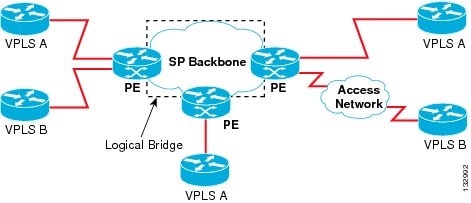
With VPLS, all CE devices participating in a single VPLS instance appear to be on the same LAN; therefore, each CE device can communicate directly with one another in a multipoint topology, without requiring a full mesh of point-to-point circuits at the CE device. In a VPLS network, CE and provider edge (PE) devices are not routing peers, so there is no need for service providers to provision customer IP routers; this is a significant advantage over MPLS L3 VPN services. Compared to traditional LAN switching technologies, VPLS is also more flexible in its geographic scaling, so that CE sites may be within the same metropolitan domain, or may be geographically dispersed on a regional or national basis.
VPLS using Label Distribution Protocol (LDP) Signaling is supported. To enable VPLS over a network, a full-mesh or ring configuration with bridge-domains (pseudowires or Ethernet Flow Points (EFPs)) must be established using the Label Distribution Protocol (LDP). Dynamic pseudowires over LDP signalled, Static Pseudowire, Traffic Engineering (TE), or Transport Profile (TP) label switched path is supported in this release.
Full-Mesh Configuration
The full-mesh configuration requires a full mesh of label-switched paths (LSPs) tunnels between all the PEs that participate in the VPLS. The tunnel label switched paths are required only for TE and TP configurations and not for LDP. With a full-mesh configuration, signaling overhead and packet replication requirements for each provisioned VC on a PE can be high.
To set up a VPLS, a virtual forwarding instance (VFI) must be created on each participating PE router. The VFI specifies the VPN ID of a VPLS domain, the addresses of other PE routers in the domain, and the type of tunnel signaling and encapsulation mechanism for each peer PE router.
The set of VFIs formed by the interconnection of the emulated VCs is called a VPLS instance; it is the VPLS instance that forms the logic bridge over a packet-switched network (PSN). The VPLS instance is assigned a unique VPN ID.
The PE routers use the VFI to establish a full-mesh LSP of emulated VCs to all the other PE routers in the VPLS instance. PE routers obtain the membership of a VPLS instance.
The full-mesh configuration allows the PE router to maintain a single broadcast domain. The CE devices view the VPLS instance as an emulated LAN.
To avoid the problem of a packet looping in the provider core, the PE devices enforce a split-horizon principle for the emulated VCs. That means if a packet is received on an emulated VC, it is not forwarded on any other emulated VC.
After the VFI has been defined, it needs to be bound to a bridge-domain to the CE device.
The packet forwarding decision is made by looking up the Layer 2 VFI of a particular VPLS domain.
A VPLS instance on a particular PE router receives Ethernet frames that enter on specific physical or logical ports and populates a MAC table similarly to how an Ethernet switch works. The PE router can use the MAC address to switch those frames into the appropriate LSP to be delivered to another PE router at a remote site.
If the MAC address is not in the MAC address table, the PE router replicates the Ethernet frame and floods it to all logical ports associated with that VPLS instance, except the ingress port where it just entered. The PE router updates the MAC table as it receives packets on specific ports and removes addresses that are not used for specific periods.
Ring Configuration
Ring configuration reduces both signaling and replication overhead, and also the bandwidth utilization for multicast traffic. Ring VPLS has an interconnection of PEs in a ring fashion. The main difference between ring and mesh VPLS is that in mesh VPLS, split horizon is enabled between the core PWs, and in a ring VPLS, split horizon is disabled. To prevent the consequential loop, at least one span in the ring is deprived of the PW configuration, that is, in a ring formed from X number of PEs, there will be (X-1) PWs with split horizon disabled.
Comparison of Mesh VPLS with Ring VPLS
VPLS builds a full mesh of connections by default. In full mesh VPLS, multiple copies of customer traffic is present in the network path. In full mesh VPLS, if the number of multicast receiving node is N, there will be around N/2~1 copies of traffic along the network path.
In ring VPLS, a single copy of customer traffic traverses the network path. IGMP snooping feature replicates multicast steam to all destination sites which have joined the multicast group. Its forwarding mechanism is similar to Ethernet multicast forwarding mechanism. Ring topology is best suited for multicast application where the receivers are distributed across the PEs. Flooding of multicast traffic in the ring can be controlled by enabling IGMP snooping on the VPLS service.
Fault Handling in Ring VPLS
It is recommended to have protected TP tunnels between all PEs for robust network. In such a topology, a single link fault has no effect on the multicast entries and has a switch time of 50 milli-seconds. To counter multiple failures in the ring, redundancy at the router end is relied upon as shown in the below figure.
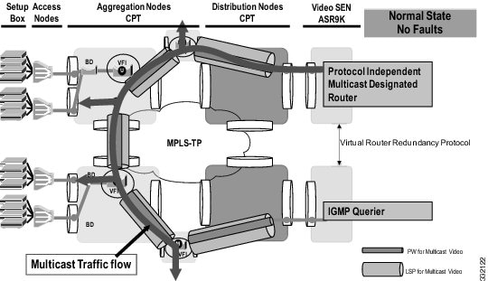
The active or the standby state at the router is handled by the native multicast protocol and redundancy configurations at the router end.
Configuring VPLS
Provisioning a VPLS link involves provisioning the associated bridge-domain and the VFI on the PE. Before you configure VPLS, ensure that the network is configured as follows:
-
(Only Dynamic MPLS) Configure IP routing in the core network so that the PE routers can reach each other through the IP.
-
Configure MPLS in the core network so that a LSP exists between the PE routers.
-
Configure a loopback interface for originating and terminating Layer 2 traffic. Make sure that the PE routers can access the loopback interface of other routers.
VPLS configuration requires you to identify peer PE routers and to attach Layer 2 circuits to the VPLS at each PE router.
- The attachment circuit (AC)-less model is used to provision PWs. There is no AC-VFI binding in any of the VPLS deployment scenarios. AC is transparent to VFI and is handled completely by the bridge-domain.
-
VC Type 5 (Ethernet) is supported and not VC Type 4 pseudowire for VPLS.
- Double tag encapsulation with rewrite POP 1 operation is not supported for VPLS EFP.
Supported Features on VPLS
Interaction of VPLS with other Features
The VPLS feature supports QoS, In-Service Software Upgrade (ISSU), High Availability (HA), and active-active forwarding. Active-Active forwarding is supported by VPLS only when graceful-restart is enabled.
The VPLS feature provides multicast support that is required for efficient video traffic distribution. This is achieved by enabling IGMP snooping on the VPLS bridge-domain. The IGMP snooping for VPLS, provides the ability to send Layer 2 multicast frames from the CE in a VPLS VFI only to those remote peer CEs that have sent an IGMP request to join the multicast group. IGMP on VPLS does not support static multicast routers.
The VPLS feature supports MAC learning and MAC flush on the VPLS bridge-domain and MAC withdrawal, based on the LDP update. VPLS-capable systems must dynamically learn MAC addresses on the EFPs and PWs and must be able to forward and replicate packets across both EFPs and PWs. MAC entries are learnt per VFI.
The VPLS feature supports Link Aggregation (LAG) on the EFP side and not the PW side.
On the EFP side, if Resilient Ethernet Protocol (REP) is enabled, the VPLS feature supports MAC flush and withdrawal when REP switchover is triggered. MAC flush is triggered when access PW switchover occurs and when the VPLS EFP comes up per bridge-domain. When the core PW goes down, the MAC flush occurs per PW. The following figure explains the REP and VPLS interaction:
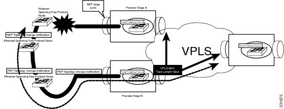
When there is a link failure, the REP ports are unblocked and the REP ring is restored in less than a second. REP access failure is propagated through REP Topology Change Notification (TCN) across the ring. REP TCN triggers MAC withdrawal and the traffic can be quickly restored over the VPLS domain
Supported Encapsulation and Rewrite Operations
The supported encapsulation and rewrite operations for VPLS are listed in Table 2.
Example: Mesh Topology
This section contains examples that show how to configure VPLS using Cisco IOS commands.
The example in this section explains how to configure VPLS in case of a mesh topology that is shown in the below figure:
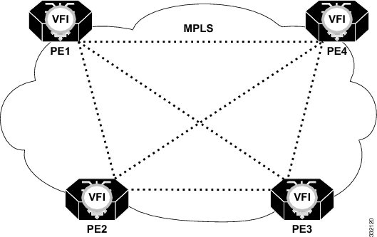
! Configuration on PE1
bridge-domain 100
mode vpls

l2 vfi vpls-100 manual
vpn id 100
bridge-domain 100
neighbor 2.2.2.2 encapsulation mpls
neighbor 3.3.3.3 encapsulation mpls
neighbor 4.4.4.4 encapsulation mpls

! Configuration on PE2
bridge-domain 100
mode vpls

l2 vfi vpls-100 manual
vpn id 100
bridge-domain 100
neighbor 1.1.1.1 encapsulation mpls
neighbor 3.3.3.3 encapsulation mpls
neighbor 4.4.4.4 encapsulation mpls

! Configuration on PE3
bridge-domain 100
mode vpls

l2 vfi vpls-100 manual
vpn id 100
bridge-domain 100
neighbor 1.1.1.1 encapsulation mpls
neighbor 2.2.2.2 encapsulation mpls
neighbor 4.4.4.4 encapsulation mpls

! Configuration on PE4
bridge-domain 100
mode vpls

l2 vfi vpls-100 manual
vpn id 100
bridge-domain 100
neighbor 1.1.1.1 encapsulation mpls
neighbor 2.2.2.2 encapsulation mpls
neighbor 3.3.3.3 encapsulation mpls
The example in this section explains how to configure VPLS in case of a ring topology that is shown in the below figure:
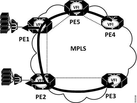
 Note | Split-horizon is disabled on PE1 and PE2 to allow packet to go from one VPLS PW to another VPLS PW |
! Configuration on PE1
bridge-domain 100
mode vpls

l2 vfi vpls-100 manual
vpn id 100
bridge-domain 100
neighbor 2.2.2.2 encapsulation mpls no-split-horizon
neighbor 4.4.4.4 encapsulation mpls no-split-horizon

Interface 36/11
Service instance 10 ethernet
Encap dot1q 10
Bridge-domain 100

! Configuration on PE2
bridge-domain 100
mode vpls

l2 vfi vpls-100 manual
vpn id 100
bridge-domain 100
neighbor 1.1.1.1 encapsulation mpls no-split-horizon
neighbor 3.3.3.3 encapsulation mpls no-split-horizon

Interface 36/12
Service instance 10 ethernet
Encap dot1q 10
Bridge-domain 100


! Configuration on PE3
bridge-domain 100
mode vpls

l2 vfi vpls-100 manual
vpn id 100
bridge-domain 100
neighbor 2.2.2.2 encapsulation mpls

Interface 4/2
Service instance 10 ethernet
Encap dot1q 10
Bridge-domain 100

! Configuration on PE4
bridge-domain 100
mode vpls

l2 vfi vpls-100 manual
vpn id 100
bridge-domain 100
neighbor 1.1.1.1 encapsulation mpls

Interface 4/2
Service instance 10 ethernet
Encap dot1q 10
Bridge-domain 100
The following example shows how to enable IGMP snooping on the VPLS bridge-domain and how to configure the source and host ports:
! Configuration on the bridge-domain
Router(config)# bridge-domain 200
Router(config-bdomain)# mode vpls
Router(config-bdomain)# ip igmp snooping

! Configuration on port 1
Router(config)# interface gi 36/1
Router(config-if)# service instance 10 ethernet
Router(config-if-srv)# encapsulation untagged
Router(config-if-srv)# bridge-domain 30

! Configuration on port 2
Router(config)# interface gi 36/2
Router(config-if)# service instance 10 ethernet
Router(config-if-srv)# encapsulation dot1q 200
Router(config-if-srv)# rewrite ingress pop 1 symmetric
Router(config-if-srv)# bridge-domain 30

! Configuration on port 3
Router(config)# interface gi 36/6
Router(config-if)# service instance 10 ethernet
Router(config-if-srv)# encapsulation dot1q 101 second-dot1q 20
Router(config-if-srv)# rewrite ingress pop 2 symmetric
Router(config-if-srv)# bridge-domain 30
The following example shows how to enable IGMP immediate leave on the VPLS bridge-domain:
Router(config)# bridge-domain 200
Router(config-bdomain)# mode vpls
Router(config-bdomain)# ip igmp snooping immediate-leave
The following example shows how to disable IGMP report suppression on the VPLS bridge-domain:
Router(config)# bridge-domain 200
Router(config-bdomain)# mode vpls
Router(config-bdomain)# no ip igmp snooping report-suppression
NTP-J107 Configure a VPLS Circuit Using CTC
| Purpose | This procedure configures a VPLS circuit using CTC. |
| Tools/Equipment | None |
| Prerequisite Procedures | None |
| Required/As Needed | As needed |
| Onsite/Remote | Onsite or remote |
| Security Level | Provisioning or higher |
| Step 1 | Complete DLP-J335 Create a VPLS Circuit Using CTC. |
| Step 2 | Create an access pseudowire on the node (user provider edge (U-PE)) that must be added to the existing VPLS circuit. The access pseudowire must be created from U-PE to an unmanaged node only. To create an access pseudowire, see DLP-J91 Create a Pseudowire Using CTC. |
| Step 3 | Complete DLP-J336 Edit a VPLS Circuit Using CTC. |
DLP-J335 Create a VPLS Circuit Using CTC
| Step 1 | Complete the NTP-J22 Log into CTC procedure at a node on the network where you want to create a VPLS circuit. | ||
| Step 2 | From the View menu, choose Go to Network View. | ||
| Step 3 | Click the Layer2+ tab. | ||
| Step 4 | From the left pane, click Circuits. | ||
| Step 5 | Click the VPLS tab. | ||
| Step 6 | Click Create. The Circuit Creation wizard appears. | ||
| Step 7 | In the Global
Attributes area of the Circuit Attributes screen, specify the global
attributes:
| ||
| Step 8 | Click Next. The VPLS Configuration screen is displayed. | ||
| Step 9 | Click Select Nodes for the VPLS Network. The Select Nodes for the VPLS Network screen is displayed. | ||
| Step 10 | To select the
nodes for the VPLS network:
| ||
| Step 11 | In the VPLS
Configuration screen, choose
NONE as
the pseudowire class from the PW Class A and PW Class Z
drop-down lists.
| ||
| Step 12 | Click Finish. | ||
| Step 13 | Return to your originating procedure (NTP). |
DLP-J336 Edit a VPLS Circuit Using CTC
| Purpose |
This procedure edits a VPLS circuit using CTC: |
| Tools/Equipment | None |
| Prerequisite Procedures | DLP-J335 Create a VPLS Circuit Using CTC |
| Required/As Needed | As needed |
| Onsite/Remote | Onsite or remote |
| Security Level | Provisioning or higher |
| Step 1 | Complete the NTP-J22 Log into CTC procedure at a node where you want to edit a VPLS circuit. | ||
| Step 2 | From the View menu, choose Go to Home View. | ||
| Step 3 | Click the Layer2+ tab. | ||
| Step 4 | Click VPLS. | ||
| Step 5 | From the list of VPLS circuits, select a VPLS circuit to edit. | ||
| Step 6 | Click Edit. The Edit Circuit dialog box appears. | ||
| Step 7 | In the General tab, view the name, description, service ID, and MTU of the VPLS circuit. | ||
| Step 8 | In the Endpoint
PWs tab, view the node list that are part of the selected VPLS circuit. Select
the node in the VPLS Node List area to view the details of its neighbor node in
the Neighbors area.
You can create new endpoints only for Ethernet Private LAN and Ethernet Virtual Private LAN. To create new endpoint PWs for this VPLS circuit:
| ||
| Step 9 | In the S-PE Nodes tab, view the node list that is part of the selected VPLS circuit. Select the node in the VPLS Node List area to view the details of its neighbor node in the Neighbors area. You can delete the neighbor and node by selecting them and clicking the Delete Neighbor or the Delete Node button. | ||
| Step 10 | In the Endpoint
EFPs tab, view the EFPs that are part of the selected VPLS. You can create new
endpoints only for Ethernet Private LAN and Ethernet Virtual Private LAN. To
create a new endpoint EFP for this VPLS:
| ||
| Step 11 | In the EFP Configuration tab, specify the VLAN configuration for the selected EFP and click Apply. | ||
| Step 12 | In the QoS tab, specify the QoS policies to apply on the individual EFPs: | ||
| Step 13 | (Only for
Ethernet Virtual Private LAN type) In the IGMP Snooping tab, specify the
settings for the bridge domain:
| ||
| Step 14 | (Only for
Ethernet Private LAN and Ethernet Virtual Private LAN types) In the MAC
Learning tab, specify the MAC learning settings for the bridge domain:
| ||
| Step 15 | In the State tab, edit the state of the VPLS circuit: | ||
| Step 16 | Return to your originating procedure (NTP). |
NTP-J108 Configure a VPLS Circuit Using Cisco IOS Commands
| Purpose | This procedure configures a VPLS circuit using Cisco IOS commands. |
| Tools/Equipment | None |
| Prerequisite Procedures | None |
| Required/As Needed | As needed |
| Onsite/Remote | Onsite or remote |
| Security Level | Provisioning or higher |
| Step 1 | Complete DLP-J216 Configure a Bridge Domain Using Cisco IOS Commands. |
| Step 2 | (Optional) Complete DLP-J1 Configure an Ethernet Service Instance Using Cisco IOS Commands when the CE is connected to the PE using Ethernet services. |
| Step 3 | Complete any one of the following procedures as applicable: |
| Step 4 | Complete DLP-J337 Create a Layer 2 Virtual Forwarding Instance Using Cisco IOS Commands. |
| Step 5 | Complete DLP-J90 Create a Pseudowire Using Cisco IOS Commands when the PE (U-PE) is connected to another PE using MPLS services. |
DLP-J337 Create a Layer 2 Virtual Forwarding Instance Using Cisco IOS Commands
| Purpose | This procedure creates a layer 2 virtual forwarding instance (VFI) using Cisco IOS commands. |
| Tools/Equipment | None |
| Prerequisite Procedures | DLP-J216 Configure a Bridge Domain Using Cisco IOS Commands (with VPLS mode) |
| Required/As Needed | As needed |
| Onsite/Remote | Onsite or remote |
| Security Level | Provisioning or higher |
 Feedback