- Preface
- New and Changed Information
- Understanding the Carrier Packet Transport System
- Hardware
- Configuring Ethernet Virtual Circuit
- Configuring Multiprotocol Label Switching
- Configuring MPLS–Transport Profile
- Configuring Pseudowire
- Configuring Virtual Private LAN Services
- Configuring Quality of Service
- Configuring High Availability
- Configuring Resilient Ethernet Protocol
- Configuring Link Aggregation Group and Link Aggregation Control Protocol
- Configuring Span
- Configuring MAC Learning
- Configuring Multicast VLAN Registration
- Configuring IGMP Snooping
- Configuring Ethernet OAM, Connectivity Fault Management, and Y.1731
- Configuring Synchronous Ethernet
- Configuring Performance Monitoring, RMON, OTN, and Port Provisioning
- Configuring Local Authentication
- Configuring Cisco Discovery Protocol
- Alarm Troubleshooting
- SNMP
- CPT Error Messages
- Support for MSTP Cards
- Network Element Defaults
- Index
- Introduction to Carrier Packet Transport Cards
- NTP-J19 Install the Fabric and Line Cards
- NTP-J72 Create a Fan–Out–Group Using CTC
- NTP-J72 Create a Fan–Out–Group Using CTC
- Understanding Rings
- NTP-J126 Configure a Ring Using CTC
- DLP-J363 Create a Single-Homed Ring Using CTC
- DLP-J364 Edit a Single-Homed Ring Using CTC
- DLP-J381 Replace an existing CPT 50 in a ring with another CPT 50
- DLP-J365 Manage the Packet Transport System View of a CPT 50 in a Ring
- DLP-J366 View Actual Topology of a Ring
- DLP-J370 Add a Node Using CTC
- DLP-J371 Set the Role of a Node Using CTC
- DLP-J377 Configure a GCC Link
- DLP-J372 Create a Dual-Homed Ring Using CTC
- DLP-J373 Edit a Dual-Homed Ring Using CTC
- DLP-J381 Replace an existing CPT 50 in a ring with another CPT 50
- DLP-J378 Change the Status of the PRC using CTC
- DLP-J376 Configure Management Virtual Forwarding Interface (VFI)
- DLP-J380 Change CPT 50 in Ring Mode to Fan-Out-Group (FOG) Mode
- DLP-J374 Upgrade CPT 50 in Fan-Out-Group (FOG) Mode to Ring Mode
- Preparing to Install the CPT 50 Shelf
- NTP-J53 Unpack and Inspect the CPT 50 Shelf
- ANSI Rack Installation
- ETSI Rack Installation
- Wall Mounting and Desktop Mounting the CPT 50 Shelf
- Laser Warning
- NTP-J54 Install the CPT 50 Shelf
- DLP-J173 Mounting the 19-inch Brackets on the CPT 50 Shelf for the ANSI Rack Configuration
- DLP-J174 Mounting the 23-inch Brackets on the CPT 50 Shelf for the ANSI Rack Configuration
- DLP-J175 Mounting the Brackets on the CPT 50 Shelf for the ETSI Rack Configuration
- DLP-J176 Mount the CPT 50 Shelf on a Rack (One Person)
- DLP-J177 Mount the CPT 50 Shelf on the Wall
- DLP-J178 Mount the CPT 50 Shelf on the Desktop
- Power Module
- Fan-Tray Assembly
- NTP-J55 Replace the Fan-Tray Assembly in the CPT 50 Shelf
- NTP-J56 Replace the Air Filter in the CPT 50 Shelf
- Power and Ground Description
- NTP-J57 Install the Power Feeds and Ground to the CPT 50 Shelf
- DLP-J179 Connect Office Power (AC) to the CPT 50 Shelf
- DLP-J180 Connect Office Power (DC) to the CPT 50 Shelf (ANSI Only)
- DLP-J181 Connect Office Power (DC) to the CPT 50 Shelf (ETSI Only)
- DLP-J182 Turn On and Verify AC Office Power on the CPT 50 Shelf
- DLP-J183 Turn On and Verify DC Office Power on the CPT 50 Shelf
- NTP-J58 Connecting Cables to the EOBC, Timing, and Console Ports
- NTP-J59 Install and Route Fiber-Optic Cables
- NTP-J60 Clean Fiber Connectors
- NTP-J61 Perform the CPT 50 Shelf Installation Acceptance Test
- Hardware Specifications
- SFP, SFP+, and XFP Modules
Hardware
This chapter describes fabric card, line card, and CPT 50 panel.
- Introduction to Carrier Packet Transport Cards
- NTP-J19 Install the Fabric and Line Cards
- NTP-J72 Create a Fan–Out–Group Using CTC
- NTP-J72 Create a Fan–Out–Group Using CTC
- Understanding Rings
- NTP-J126 Configure a Ring Using CTC
- Preparing to Install the CPT 50 Shelf
- NTP-J53 Unpack and Inspect the CPT 50 Shelf
- ANSI Rack Installation
- ETSI Rack Installation
- Wall Mounting and Desktop Mounting the CPT 50 Shelf
- Laser Warning
- NTP-J54 Install the CPT 50 Shelf
- Power Module
- Fan-Tray Assembly
- NTP-J55 Replace the Fan-Tray Assembly in the CPT 50 Shelf
- NTP-J56 Replace the Air Filter in the CPT 50 Shelf
- Power and Ground Description
- NTP-J57 Install the Power Feeds and Ground to the CPT 50 Shelf
- NTP-J58 Connecting Cables to the EOBC, Timing, and Console Ports
- NTP-J59 Install and Route Fiber-Optic Cables
- NTP-J60 Clean Fiber Connectors
- NTP-J61 Perform the CPT 50 Shelf Installation Acceptance Test
- Hardware Specifications
- SFP, SFP+, and XFP Modules
Introduction to Carrier Packet Transport Cards
This topic describes the Carrier Packet Transport (CPT) cards. There are two cards in the CPT system:
The CPT 50 panel is a standalone unit and can be connected to the CPT system. The CPT 50 panel enables the number of ports to be scaled on the CPT system.
These cards are supported on the CPT 200 and CPT 600 platforms. The CPT system complies with RoHS-6 standards.
The following system configuration is recommended on the CPT 200 shelf:
The following system configuration is recommended on the CPT 600 shelf:
Fabric Card
(CPT 200 and CPT 600 only)
The fabric card is a single slot card with two 10GE SFP+ ports and two 10GE XFP ports. The XFP ports on the fabric card support the Optical Transport Network (OTN) protocol. The SFP+ ports on the fabric card can serve as normal ports or InterConnect (IC) ports. When the SFP+ ports are used as IC ports, these ports are used to connect with the SFP+ ports on the CPT 50 panel.
The fabric card runs the route processor version of IOS. The fabric card manages the line card and the CPT 50 panel through the backplane GE management channel.
When fabric and line cards are installed on the shelf, a bidirectional 2 * 16G connection is set up between each fabric and line card and also between two fabric cards.
In chassis AC type, two fabric and two line cards are supported. In chassis DC type, there is no limit on the cards that are supported.
Circuit creation is possible only at XFP ports of the fabric card. Only OCHTRAIL creation is supported. Before creating the OCHTRAIL, create a provisionable patchcord (PPC) between the XFP port of the fabric card and the OCH port.
Slot Compatibility
On the CPT 600 shelf, install the redundant fabric cards in slots 4 and 5. There can be up to 2 fabric cards on the CPT 600 shelf. The two fabric cards on the CPT 600 shelf can both be in active mode with both cards carrying the traffic.
On the CPT 200 shelf, install the fabric card in slot 2 or 3.
Faceplate and Block Diagram
Figure 1 illustrates the faceplate of the fabric card.
The FPGA on the fabric card processes the traffic packets. The console port on the faceplate is used for debugging.

Figure 2 illustrates the CPT system block diagram.
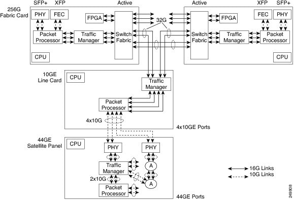
Card-Level Indicators
| Card-Level LED | Description |
|---|---|
Red FAIL LED |
The red FAIL LED indicates that the processor of the card is not ready. This LED is on during the reset. The FAIL LED flashes during the boot process. Replace the card if the red FAIL LED persists. |
Green ACT LED |
If the ACT LED is green, the card is operational (one or more ports active) and ready to carry the traffic. |
Amber SF LED |
The amber SF LED indicates that a signal failure or condition such as LOS, LOF, or high BERs is present in one or more of the ports of the card. The amber SF LED is also on if the transmit and receive fibers are incorrectly connected. If the fibers are properly connected and the link is working, the light turns off. |
Port-Level Indicators
A port status LED is provided for each SFP+ port and XFP port on the fabric card. The XFP ports on the fabric card have only Link LEDs and no ACT LEDs.
| Port-Level LED | Description |
|---|---|
Link LED |
Green—The port is either in–service and receiving a recognized signal (that is, no signal fail), or out–of–service and maintenance (OOS,MT or locked, maintenance) in which case the signal fail and alarms are ignored. Red—The port is in–service but is receiving a signal fail (LOS). Amber—The port is provisioned and is in a standby state. |
ACT LED |
Indicates data reception. The LED blinks on packet flow. |
Line Card
(CPT 200 and CPT 600 only)
The line card has four 10GE SFP+ ports. The SFP+ ports on the line card serve as normal ports or InterConnect (IC) ports. When the SFP+ ports are used as IC ports, these ports are used to connect with the SFP+ ports on the CPT 50 panel. The line card runs the line card version of IOS.
When fabric and line cards are installed on the shelf, a bidirectional 2 * 16G connection is set up between each fabric card and each line card and also between two fabric cards.
Slot Compatibility
On the CPT 600 shelf, install the line cards in slots 2, 3, 6, and 7. There can be up to four line cards on the CPT 600 shelf. However, the line card is not required to be present on the CPT 600 shelf.
On the CPT 200 shelf, install the line card in slot 2 or 3. There can be a single line card on the CPT 200 shelf. However, the line card is not required to be present on the CPT 200 shelf.
Line Card States
The line card could be in one of the following states:
Faceplate
Figure 1 illustrates the faceplate for the line card. The console port on the faceplate is used for debugging.

Card-Level Indicators
Table 1 provides information on card–level indicators.
Port-Level Indicators
A port status LED is provided for each SFP+ port on the line card.
Table 2 provides information on port–level indicators.
CPT 50 Panel
(CPT 200 and CPT 600 only)
The CPT 50 panel enables the number of ports to be scaled on the CPT system. The CPT 50 panel has 4 10GE SFP+ ports and 44 GE SFP ports. The CPT 50 panel runs the line card version of IOS.
 Note | The CPT 50 panel is not placed in the CPT 200 or CPT 600 shelf. |
Note | The CPT 50 panel should be of REV 5 hardware. To check the hardware, run the following command: show version. |
The CPT 50 panel cannot operate independently. After connecting the CPT 50 panel to the fabric card or the line card, the CPT 50 panel is automatically discovered and registered. The discovery operation is performed using the Satellite Discovery Protocol (SDP) and the registration operation is performed using the Satellite Registration Protocol (SRP).
The four SFP+ ports on the CPT 50 panel can be connected to the SFP+ ports on the fabric card or the line card. The four SFP+ ports on the CPT 50 panel can be connected to only one card (fabric or line card) at a time.
CPT 50 shelf supports ONE-GE and FE for 1 to 44 ports. CPT 50 shelf supports TEN-GE for 45 to 48 ports. By default, the 45 to 48 ports are in IC mode and cannot be changed.
The CPT 50 panel has redundant DC feeds. The CPT 50 panel DC power supply can handle 48 V and 24 V. The 48 V power supply has both ANSI and ETSI versions.
The CPT 50 panel has a removable fan tray and a local console port for onsite access and debugging.
TDM SFP on a CPT 50 panel is supported even if the other end of the static pseudowire is connected to a Cisco ASR 9000 Series Router or a Cisco 7600 Series Router.
Faceplate
There are four variations of the CPT 50 panel faceplate:
-
CPT 50 panel with AC power. See Figure 1.
-
CPT 50 panel with DC ETSI 48 V. See Figure 2.
-
CPT 50 panel with DC ANSI 48 V. See Figure 3.
-
CPT 50 panel with DC ANSI 24 V. See Figure 4.
Card–Level Indicators
| Card-Level LED | Description |
|---|---|
| PWR | Indicates the status of the power to the card. If there is a power failure, this LED turns red. |
| FAN | Indicates the status of the fan to the card. If there is a fan failure, this LED turns red. |
| CRIT | Indicates the critical alarms in the network at the local terminal. |
| MAJ | Indicates the major alarms in the network at the local terminal. |
| MIN | Indicates the minor alarms in the network at the local terminal. |
Supported CPT 50 Panels on the CPT System
-
The CPT system supports up to 20 CPT 50 panels or 880 GE ports on the CPT 600 shelf.
-
The CPT system supports up to 6 CPT 50 panels or 264 GE ports on the CPT 200 shelf.
The limit on the number of ports is not enforced by CTC.
CPT 50 Panel States
The following states are defined for a CPT 50 panel that is configured in the CPT system:
-
Pre–provisioned—When the 10GE ports on the fabric or the line card are configured as IC ports and when these IC ports are associated with a Fan-Out-Group (FOG).
-
Loading—When the CPT 50 panel has booted up with the IOS image and when the line card version of IOS is being downloaded from the fabric card.
-
Active—When the CPT 50 panel boots up with the line card image and the application initialization is completed.
CPT 50 Panel Connectivity to the Fabric or Line Card
If the CPT 50 shelf loses connectivity to the fabric or line card due to interconnect (IC) link down events, the CPT 50 shelf reloads after the last IC link in the FOG (Fan-Out-Group) fails. This reload occurs after the configured carrier time delay. If there is a connection loss due to remote failures, the CPT 50 shelf reloads after detecting the failure time-out period (5 seconds) for the last link that was active. When the reload is complete, the CPT 50 shelf tries to reestablish the connection to the fabric or line card by performing the discovery operation. If the discovery operation is not successful within 5 minutes, the CPT 50 shelf reloads again. This cycle is repeated thrice with a reduction in the time-out period (30 seconds), until the discovery operation is successful. In the event of successful discovery, the CPT 50 shelf reestablishes the connection to the fabric or line card, else the CPT 50 shelf transits to the idle state and then attempts to connect to the fabric or line card.
Interlink Protection
If one of the links in the FOG is down, the traffic sent on that link is switched and distributed to the remaining active links in the FOG.
Hardware Restrictions
At any given time, only 12 TDM SFP modules can be connected to a CPT 50 panel. With these modules, 15 SFP modules and 2 SFP+ modules can also be connected. For information about SFP and SFP+ modules, see the Pluggables compatible with Cisco CPT 50.These SFP and SFP+ modules can be connected to only selected ports of the CPT 50 panel. See
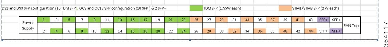
Only the ports highlighted in green can be used to connect TDM SFP modules or any other SFP modules. The ports highlighted in purple can be used only to connect SFP+ modules.
Note | Ensure to close the remaining ports with cage caps. The Cisco part number for a cage cap is 51-2870-01. |
Software Restrictions
The following software restrictions apply to the CPT 50 panel:
-
The CPT system supports up to 880 GE ports on the CPT 600 shelf and these ports are distributed among 1 to 20 CPT 50 panels.
-
The CPT system supports up to 264 GE ports on the CPT 200 shelf and these ports are distributed among 1 to 6 CPT 50 panels.
The limit on the number of ports is not enforced by CTC.
-
Each CPT 50 panel can be connected to only one fabric or line card at a time.
-
Only one FOG can be created for each CPT 50 panel.
Pre-provisioning
The following can be pre-provisioned through CTC:
The ONE-GE and FE PPMs are not pre-provisioned by default.
NTP-J19 Install the Fabric and Line Cards
| Purpose | (CPT 200 and CPT 600 only) This procedure installs the fabric and line cards on the CPT 200 and CPT 600 shelves. On the CPT 600 shelf, install the redundant fabric cards in slots 4 and 5. On the CPT 200 shelf, install the fabric card in slots 2 or 3. On the CPT 600 shelf, install the line cards in slots 2, 3, 6, and 7. On the CPT 200 shelf, install the line card in slots 2 or 3. |
| Tools/Equipment | Fabric and line cards. |
| Prerequisite Procedures | DLP–G604 Install the TNC or TSC Card in Cisco ONS 15454 DWDM Configuration Guide |
| Required/As Needed | Required |
| Onsite/Remote | Onsite |
| Security Level | None |
 Warning | During this procedure, wear grounding wrist straps to avoid ESD damage to the card. Do not directly touch the backplane with your hand or any metal tool, or you could shock yourself. Statement 94 |
Warning | Class 1 laser product. Statement 1008 |
Warning | Invisible laser radiation may be emitted from the end of the unterminated fiber cable or connector. Do not view directly with optical instruments. Viewing the laser output with certain optical instruments (for example, eye loupes, magnifiers, and microscopes) within a distance of 100 mm may pose an eye hazard. Statement 1056 |
Warning | Class 1 laser product. Statement 1008 |
 Caution | Always use the supplied ESD wristband when working with a CPT 200 and CPT 600 shelf. For detailed instructions on how to wear the ESD wristband, refer to the Electrostatic Discharge and Grounding Guide for Cisco CPT and Cisco ONS Platforms. |
Note | If protective clips are installed on the backplane connectors of the cards, remove the clips before installing the cards. |
Note | If you install a card incorrectly, the FAIL LED flashes continuously. |
NTP-J72 Create a Fan–Out–Group Using CTC
| Purpose | This procedure creates a Fan–Out–Group (FOG) using CTC. |
| Tools/Equipment | None |
| Prerequisite Procedures | None |
| Required/As Needed | As needed |
| Onsite/Remote | Onsite or remote |
| Security Level | Provisioning or higher |
By default, the SFP+ ports on the fabric or line cards are configured as 10GE ports. These ports need to be configured as IC ports and associated to a FOG to connect these ports to the CPT 50 panel. FOG is a logical channel that consists of a bundle of 10GE IC ports.
The CPT 50 panel can be connected to the fabric card using two IC ports. The CPT 50 panel can be connected to the line card using four IC ports.
The 4 SFP+ ports that are displayed as 1+ 2+ 3+ 4+ on the faceplate of the CPT 50 panel are displayed as 45, 46, 47, 48 in CTC. This includes the display in Alarms and Performance Monitoring.
Note | You can create only one FOG for each CPT 50 panel. |
| Step 1 | Complete the NTP-J22 Log into CTC procedure at a node where you want to configure the SFP+ ports as IC ports. | ||
| Step 2 | From the View menu, choose Go to Home View. | ||
| Step 3 | Right-click the fabric or line card and choose Open Packet Transport System View. The Packet Transport System View dialog box appears. | ||
| Step 4 | Click the Fan-Out Groups tab. | ||
| Step 5 | Click Create. The Create/Edit Fan-Out Group dialog box appears. | ||
| Step 6 | Enter the name of the fan-out-group in the Name field. This name is used for the CPT-50 panel. | ||
| Step 7 | From the Fan-Out Group ID drop-down list, choose a FOG ID. FOG ID is the virtual slot ID of the CPT 50 panel and takes values from FOG 36 to FOG 55. | ||
| Step 8 | From the Card Slot drop-down list, choose a slot. | ||
| Step 9 | In the Interlink Queuing Mode area, choose one of the following options:
| ||
| Step 10 | From the Available Fan–Out Ports area, choose the required ports that you want to configure as IC ports and move these ports to the Available Fan–Out Group Member Ports area. | ||
| Step 11 |
Click Apply to create a FOG that consists of the selected ports.
Stop. You have completed this procedure. |
Understanding Rings
The Carrier Packet Transport (CPT) system provides the ability to operate CPT 50 in a physical ring homed back to a single CPT 600 or CPT 200 chassis. This feature provides the flexibility of connecting CPT 50 in a closed-ended ring or an open-ended ring. As a result, the failure of a line or uplink card does not impact the traffic in a ring. CPT 50 in a ring works like a route processor and each CPT 50 interacts with Transport Node Controller (TNC) directly.
These sections describe more about the rings feature in CPT:
- Common Terms in Rings
- Ring Types
- Supported Traffic Patterns
- Supported CPT 50 Rings Deployment Scenario
- Limitations and Restrictions
Common Terms in Rings
This section describes the common terms in rings.
-
Topology discovery - This refers to the functionality that discovers nodes in a CPT 50 ring using REP and report it to the topology management functions residing on TNC.
-
CPT 50 in a ring - This is an instance of CPT 50 that is loaded with the CPT 50 rings software and deployed in a ring subtended from CPT 600 or CPT 200.
-
Ring Controller - For a provisioned ring, this refers to the following: -
Open-ended ring - This is a type of ring that is connected to CPT 600 or CPT 200 through only one interface and does not terminate on the headend. Hence, only one unprotected path gets available to the traffic on the ring.
-
Closed-ended ring - This is a type of ring that is provisioned to connect to CPT 600 or CPT 200 through two interfaces on CPT 600 or 200. Hence, a protected path gets available to the traffic either through the east or west interface on the ring.
-
Working Ring Controller (WRC) - For a provisioned dual-homed ring, this refers to other CPT 600 or CPT 200 network element from which the provisioned ring is subtended.
-
Protect Ring Controller (PRC) - For a provisioned dual-homed ring, this refers to the other CPT 600 or 200 network element that provide node protection to WRC.
- Ring island - This indicates a ring of the
CPT 50s that has lost the connectivity to CPT 600 or CPT 200.
In open-ended ring, ring islands are caused by a single link failure from the east port of the ring controller. This can also be caused by a failure of one of the CPT 50s in the ring.
In closed-ended ring, ring islands are caused by two link failures between the east and the west port of the ring controller.
In dual homed ring, ring islands are caused by two link failures between the ring ports of the ring controller. This can also be caused by a failure of one of the CPT 50s in the ring.
-
Golden image - This is an image stored on the CPT 50 panel that runs a software to establish control connection between the CPT 50 and CPT 600 or CPT 200 and downloads the kernel image from it.
-
Kernel image - This refers to the CPT 50 application image that is downloaded by the golden image.
-
Boot Up - This is a boot-up sequence for CPT 50 that comprises the following steps: -
Download kernel image, and allow the Boot VLAN transit traffic.
-
Boot to kernel image, and allow boot VLAN and control VLAN transit traffic based on the REP convergence.
-
Discover a unique identifier (ID) for CPT 50 and IP address from TNC.
-
Discover active TNC, and establish a connectivity with TNC.
-
Download database from TNC, and restore equipment and service configurations.
-
Ring Types
CPT supports the following types of ring:
Single-Homed Ring
A Single-homed ring is the ring that is subtending from a single CPT-600 or CPT 200 in a linear or close-ended form. Following are the types of single-homed ring:Open-Ended Ring
An Open-ended ring is the ring that is connected to a CPT 200 or CPT 600 through one port. It follows the linear topology. To create this type of ring, only the east port is required.
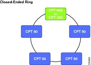
Closed-Ended Ring
A Closed-ended ring is the ring that is connected to a CPT 200 or CPT 600 through two interfaces. It follows the ring topology. To create this type of ring, both the east and west ports are required. It provides protection to the circuits and the control traffic.
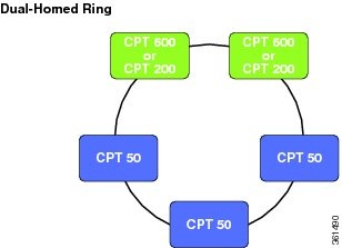
Dual-Homed Ring
A Dual-homed ring is the ring whose east port exists on one CPT 200 or CPT 600 (WRC) and west port exists on another CPT 200 or CPT 600 (PRC). If WRC fails, this type of ring provides access to all the CPT 50s in the ring by switching the traffic to the other controller.
Supported Traffic Patterns
The following MPLS-TP tunnel traffic is supported over a ring:
-
Protected or unprotected MPLS–TP tunnel traffic from CPT 50 to the headend (CPT 600 or CPT 200).
-
Protected or unprotected MPLS-TP tunnel traffic from CPT 50 to another CPT 50 in the same ring controller.
-
Protected or unprotected MPLS-TP tunnel traffic from CPT 50 to another CPT 50 in another ring on the same headend.
-
Protected or unprotected MPLS-TP tunnel traffic from CPT 50 to another CPT600 or CPT 200 that is reachable through the ring controller.
-
Protected or unprotected MPLS-TP tunnel traffic from CPT 50 to another CPT 50 (in a ring) in another CPT 600 or CPT 200 that is reachable through the ring controller.
-
Protected or unprotected MPLS-TP tunnel traffic from CPT 50 to another CPT 50 (in a fan-out group) in another CPT 600 or CPT 200 that is reachable through the ring controller.
-
Ethernet services from CPT 50 UNI (front ports) realized through VPWS or VPLS over MPLS-TP tunnels on the ring.
-
MPLS traffic from CPT 50 front ports stitched to VPLS or VPWS services over MPLS-TP tunnels on the ring.
-
MS-PWE3 traffic from the core stitched to VPLS or VPWS services over the MPLS-TP tunnels on the ring.
-
Multipoint E-LAN services with local connect .
Supported CPT 50 Rings Deployment Scenario
The CPT 50 rings architecture is raised over the CPT 50 standalone framework. CPT 50 in a ring provides a ring-based protection to the data path and the control path.
A ring can be subtended from a single CPT 600 or CPT 200 in a linear or close-ended form and are termed as single-homed rings. It can also be subtended from two interconnected CPT 600 or CPT 200 and are termed as dual-homed rings. From a CPT 600, 20 open-ended and 10 closed-ended single-homed rings can be subtended and up to 10 dual-homed rings can be subtended. From a CPT 200, six open-ended and three closed-ended single-homed rings can be subtended and up to three dual-homed rings can be subtended.
The CPT-50 support MPLS-TP based transport over the single-homed and dual-homed rings.
E-Line is realized using VPWS across the rings. E-LAN is realized using VPLS across the rings and using local switching within a CPT-50. Carrier Ethernet is not supported across the ring. Carrier Ethernet services in this case indicate E-Line and E-LAN services realized through P2P and P2MP Ethernet switching .
CPT 50 in ring mode can be provisioned through CTC only. This section describes the scenarios in which a ring can be configured using CPT 50 and the supported software features.
MPLS-TP Tunnels in a Ring
MPLS-TP tunnels in a ring can be created manually using CTC or Cisco IOS mode. BFD-based fault detection for MPLS-TP tunnels is supported at 50ms granularity using software mechanisms. It is also possible to create unprotected MPLS-TP tunnels. Only MPLS-TP data path circuit is supported over a ring. Protected MPLS-TP tunnels cannot be created in an open-ended ring as there is no alternate path available in such a configuration.
In a dual-homed ring, it is possible to create protected MPLS-TP Tunnels to WRC or PRC across the dual-homed ring and the inter-RC link spans.
VPWS in a Closed-Ended Rings
The VPWS port-based pseudowires can be created through MPLS-TP tunnels that are created within a ring or across rings. You cannot create a pseudowire in a ring if the chassis on which the corresponding attachment circuit exists, is down
VPLS in a Closed-Ended Ring
CPT 50 in a closed-ended ring can participate in the open ring or hub-and-spoke models of VPLS.
Local Switching
CPT supports local switching in a ring. Local switching allows switching of Layer 2 data between two attachment circuits on the same CPT 50 in the ring. In local switching (also known as hairpin connection), frames from one interface are switched to another interface on the same CPT 50 in a ring.
VPWS and VPLS in a Dual-Homed Ring
In a dual-homed ring, CPT 50 can participate in VPWS and VPLS by using either unprotected or protected pseudowires, terminating either at WRC or PRC.
Limitations and Restrictions
These limitations and restrictions apply to the ring in CPT:
-
A maximum of 20 open-ended, 10 closed-ended and 20 dual-homed rings can be provisioned with CPT 600 and a maximum of 6 open-ended, 3 closed-ended and 6 dual-homed rings can be provisioned with CPT 200.
-
A maximum of 15 CPT 50 panels can be configured in a ring.
-
A maximum of 40 CPT 50 panels can be configured across all the rings (single-homed or dual-homed), on a single CPT 600 or CPT 200.
-
The Resilient Ethernet Protocol (REP) configurations are internally provisioned on the ring.
-
A ring cannot be configured on the XFP port.
-
A CPT 600 or CPT 200 chassis can only have one role at a given time. It can be WRC, PRC or Single home.
-
The ports that already have Fan-Out-Group (FOG) configured, cannot be used for creating a ring.
-
The east port cannot be same as the west port while creating a single-homed ring.
-
Services must be configured on the WRC of the dual-homed ring only, in the CTC mode and it should be in up state. It can be configured on the PRC when the WRC is down, but it is not recommended.
-
In a dual-homed ring, in case of span failure service provisioning can be done only on the CPT 50's connected through the WRC, up to the first span failure .
-
If a CPT 600 or CPT 200 chassis is used in dual-homed ring, it cannot be used in the single-homed ring.
-
Both the WRC and the PRC should be in up state to perform any ring related provisioning on the dual-homed ring.
-
Layer 1 and Layer 2 configurations should not be done on the dual-homed ring when the WRC is down, through the CTC and IOS mode.
-
Services must not be configured on the ring and the Interconnect (IC) link ports when the node is in the IOS mode.
-
Ring segment ID and normal REP segment ID must be different.
-
Alarm synching is not supported from WRC to PRC and vice versa.
-
Do not remove or change the REP parameters on the ring interface as it causes data loss and separation of CPT50 from the ring.
-
Normal REP must not be configured on the Interconnect (IC) link port of a dual-homed ring.
NTP-J126 Configure a Ring Using CTC
| Purpose |
This procedure configures a ring. |
| Tools/Equipment | None |
| Prerequisite Procedures | None |
| Required/As Needed | As needed |
| Onsite/Remote | Onsite or remote |
| Security Level | Provisioning or higher |
| Step 1 | Perform any of
the following procedures as needed to configure a single-homed ring:
Stop. You have completed this procedure. |
| Step 2 | Perform the
following procedures as needed to configure a dual-homed ring:
Stop. You have completed this procedure. |
DLP-J363 Create a Single-Homed Ring Using CTC
| Purpose | This procedure allows you to do the following: |
| Tools/Equipment | None |
| Prerequisite Procedures | DLP-J371 Set the Role of a Node Using CTC |
| Required/As Needed | As needed |
| Onsite/Remote | Onsite or remote |
| Security Level | Provisioning or higher |
| Step 1 | Complete the NTP-J22 Log into CTC procedure at a node where you want to create a single-homed ring. | ||
| Step 2 | From the View menu, choose Go to Home View. | ||
| Step 3 | Right-click the fabric or line card and choose Open Packet Transport System View. The Packet Transport System View dialog box appears. | ||
| Step 4 | Click the Rings tab. | ||
| Step 5 | Click Create. The Ring Creation wizard appears. | ||
| Step 6 | In the Ring
Attributes area, specify the ring attributes as follows:
| ||
| Step 7 | To add a CPT 50 in the ring, complete the following steps: | ||
| Step 8 | From the Service
drop-down list, choose
Enable.
| ||
| Step 9 | Return to your originating procedure (NTP). |
DLP-J364 Edit a Single-Homed Ring Using CTC
| Purpose | This procedure edits a ring using CTC. |
| Tools/Equipment | None |
| Prerequisite Procedures | DLP-J363 Create a Single-Homed Ring Using CTC |
| Required/As Needed | As needed |
| Onsite/Remote | Onsite or remote |
| Security Level | Provisioning or higher |
| Step 1 | Complete the NTP-J22 Log into CTC procedure at a node where you want to edit a ring. | ||||||
| Step 2 | From the View menu, choose Go to Home View. | ||||||
| Step 3 | Right-click the fabric or line card and choose Open Packet Transport System View. The Packet Transport System View dialog box appears. | ||||||
| Step 4 | Click the Rings tab. | ||||||
| Step 5 | From the list of rings, select a ring to edit. | ||||||
| Step 6 | Click Edit. The Ring Preview screen appears. | ||||||
| Step 7 | Right click the
CPT 50 and perform any of the following:
| ||||||
| Step 8 | From the Service
drop-down list, choose
Enable.
| ||||||
| Step 9 | Return to your originating procedure (NTP). |
DLP-J381 Replace an existing CPT 50 in a ring with another CPT 50
| Purpose | This procedure allows you to replace an existing CPT 50 in a ring with another CPT 50. |
| Tools/Equipment | None |
| Prerequisite Procedures | NTP-J109 Upgrade the Cisco CPT Software |
| Required/As Needed | As needed |
| Onsite/Remote | Onsite or remote |
| Security Level | Provisioning or higher |
Perform the following steps to replace an existing CPT 50 in a ring with another CPT 50.
Note | If the CPT-50 is already used in 9.7.0, please follow only steps 6 to 10. |
| Step 1 | Physically add a new CPT 50 to the node. The port should not be a ring port | ||||
| Step 2 | Create FOG on
the newly added CPT 50 using CTC. After creating FOG, CPT 50 will be in LC-slot
with LC image.
| ||||
| Step 3 | Run the
following command to check the golden image version: show version
| ||||
| Step 4 | Set device identifier of the new CPT50 same as the existing CPT 50 using the following commands: test deviceidentifier set <name> | ||||
| Step 5 | Set device description of the new CPT50 same as the existing CPT 50 using the following commands: test devicedescription set <name> | ||||
| Step 6 | Run the following command to check whether the device identifier and description fields are set properly: show version | ||||
| Step 7 | Run the following command to change the mode from FANOUT to ring: test satMode ring | ||||
| Step 8 | Delete the FOG from the CTC. Now the new CPT 50 will reboot with the latest golden image. | ||||
| Step 9 | Physically
replace a new CPT 50 in the ring.
| ||||
| Step 10 | Make east and west port connections. Now new CPT 50 automatically downloads the application image and comes up with all the services configured on the replaced CPT 50. | ||||
| Step 11 | Return to your originating procedure (NTP). |
DLP-J365 Manage the Packet Transport System View of a CPT 50 in a Ring
| Purpose |
This procedure manages the Packet Transport System (PTS) view of a CPT 50 in a ring. |
| Tools/Equipment | None |
| Prerequisite Procedures | None |
| Required/As Needed | As needed |
| Onsite/Remote | Onsite or remote |
| Security Level | None |
| Step 1 | Complete the NTP-J22 Log into CTC procedure at a node where you want to manage the PTS view of a CPT 50 in a ring. | |||||||||||||||||||||||||||||||||||||||||||||||||||||||
| Step 2 | Right-click the fabric or line card and choose Open Packet Transport System View . The Packet Transport System View dialog box appears. | |||||||||||||||||||||||||||||||||||||||||||||||||||||||
| Step 3 | Click the Rings tab. | |||||||||||||||||||||||||||||||||||||||||||||||||||||||
| Step 4 | Choose a ring to edit and click Edit. The Ring Preview screen appears. | |||||||||||||||||||||||||||||||||||||||||||||||||||||||
| Step 5 | Right-click the CPT 50 and choose Open PTS View. The CPT50 PTS View dialog box appears. | |||||||||||||||||||||||||||||||||||||||||||||||||||||||
| Step 6 | The CPT50 PTS
View dialog box consists following tabs:
The following table lists all the configurations that you can perform in the Provisioning tab.
The following table lists all the configurations that you can perform in the Maintenance tab.
The following table lists all the configurations that you can perform in the Service Level Alarms tab.
| |||||||||||||||||||||||||||||||||||||||||||||||||||||||
| Step 7 | Return to your originating procedure (NTP). |
DLP-J366 View Actual Topology of a Ring
| Purpose | This procedure provides a graphical representation of the actual ring topology in the field. |
| Tools/Equipment | None |
| Prerequisite Procedures | DLP-J363 Create a Single-Homed Ring Using CTC |
| Required/As Needed | As needed |
| Onsite/Remote | Onsite or remote |
| Security Level | Provisioning or higher |
| Step 1 | Complete the NTP-J22 Log into CTC procedure at a node where you want to view the actual topology of a ring. | ||
| Step 2 | From the View menu, choose Go to Home View. | ||
| Step 3 | Right-click the fabric or line card and choose Open Packet Transport System View. The Packet Transport System View dialog box appears. | ||
| Step 4 | Click the Rings tab. | ||
| Step 5 | Select a ring and click Show Actual Topology.
| ||
| Step 6 | Return to your originating procedure (NTP). |
DLP-J370 Add a Node Using CTC
| Purpose | This procedure allows you to add a node. |
| Tools/Equipment | None |
| Prerequisite Procedures | None |
| Required/As Needed | As needed |
| Onsite/Remote | Onsite or remote |
| Security Level | Provisioning or higher |
| Step 1 | Complete the NTP-J22 Log into CTC procedure at a node where you want to create a dual-homed ring. |
| Step 2 | From the File menu, choose Add Node to add a new node in the network. |
| Step 3 | In the Add Node dialog box, enter the node name and click Ok. |
| Step 4 | Return to your originating procedure (NTP). |
DLP-J371 Set the Role of a Node Using CTC
| Purpose | This procedure sets the role of a node using CTC. |
| Tools/Equipment | None |
| Prerequisite Procedures | None |
| Required/As Needed | As needed |
| Onsite/Remote | Onsite or remote |
| Security Level | Provisioning or higher |
| Step 1 | Complete the NTP-J22 Log into CTC procedure at a node where you want to create a ring. |
| Step 2 | From the View menu, choose Go to Home View. |
| Step 3 | Right-click the fabric or line card and choose Open Packet Transport System View. The Packet Transport System View dialog box appears. |
| Step 4 | Click the Node Role tab. |
| Step 5 | In the Node
Role Configuration pane, specify the dual-homed ring attributes as follows:
|
| Step 6 | Click Apply. |
| Step 7 | Return to your originating procedure (NTP). |
DLP-J377 Configure a GCC Link
| Purpose | This procedure allows you to configure a generic communication channel (GCC) link. |
| Tools/Equipment | None |
| Prerequisite Procedures | None |
| Required/As Needed | As needed |
| Onsite/Remote | Onsite or remote |
| Security Level | Provisioning or higher |
| Step 1 | Complete the NTP-J22 Log into CTC procedure at a node where you want to configure a GCC link. | ||
| Step 2 | In the node view (single-shelf mode), click the Provisioning > Comm Channels > GCC tabs. | ||
| Step 3 | Click Create. The Create GCC Terminations screen appears. | ||
| Step 4 | Choose the port and slot to set the GCC termination point. | ||
| Step 5 | From the GCC
Rate drop-down list, choose the GCC rate.
| ||
| Step 6 | Click
Finish.
| ||
| Step 7 | Return to your
originating procedure (NTP).
|
DLP-J372 Create a Dual-Homed Ring Using CTC
| Purpose | This procedure allows you to create a dual-homed ring. |
| Tools/Equipment | None |
| Prerequisite Procedures | None |
| Required/As Needed | As needed |
| Onsite/Remote | Onsite or remote |
| Security Level | Provisioning or higher |
| Step 1 | Complete the NTP-J22 Log into CTC procedure at a node where you want to create a dual-homed ring. | ||
| Step 2 | From the View menu, choose Go to Network View. | ||
| Step 3 | Click the Dual Home tab. | ||
| Step 4 | Click Create. The Dual Home Ring Creation wizard appears. | ||
| Step 5 | In the Dual Home Attributes area, specify the dual-homed ring attributes as follows: | ||
| Step 6 | In the Dual Home Origination screen of the wizard | ||
| Step 7 | In the Dual Home Termination screen of the wizard | ||
| Step 8 | Click
Display
Dual-Homed Ring
to view the ring.
| ||
| Step 9 | Return to your originating procedure (NTP). |
DLP-J373 Edit a Dual-Homed Ring Using CTC
| Purpose | This procedure edits a dual-homed ring and add CPT 50's in the dual-homed ring using CTC. |
| Tools/Equipment | None |
| Prerequisite Procedures | DLP-J372 Create a Dual-Homed Ring Using CTC |
| Required/As Needed | As needed |
| Onsite/Remote | Onsite or remote |
| Security Level | Provisioning or higher |
| Step 1 | Complete the NTP-J22 Log into CTC procedure at a node where you want to edit a dual-homed ring. | ||
| Step 2 | From the View menu, choose Go to Home View. | ||
| Step 3 | Click the Dual Home tab. | ||
| Step 4 | From the list of rings, select a ring to edit. | ||
| Step 5 | Click Edit. The Dual Home Ring Preview screen appears. | ||
| Step 6 | In the Rings
Attributes area, specify the ring attributes as follows:
| ||
| Step 7 | To add a CPT 50
in the ring, complete the following steps:
| ||
| Step 8 | Click Finish. | ||
| Step 9 | Return to your
originating procedure (NTP).
|
DLP-J381 Replace an existing CPT 50 in a ring with another CPT 50
| Purpose | This procedure allows you to replace an existing CPT 50 in a ring with another CPT 50. |
| Tools/Equipment | None |
| Prerequisite Procedures | NTP-J109 Upgrade the Cisco CPT Software |
| Required/As Needed | As needed |
| Onsite/Remote | Onsite or remote |
| Security Level | Provisioning or higher |
Perform the following steps to replace an existing CPT 50 in a ring with another CPT 50.
Note | If the CPT-50 is already used in 9.7.0, please follow only steps 6 to 10. |
| Step 1 | Physically add a new CPT 50 to the node. The port should not be a ring port | ||||
| Step 2 | Create FOG on
the newly added CPT 50 using CTC. After creating FOG, CPT 50 will be in LC-slot
with LC image.
| ||||
| Step 3 | Run the
following command to check the golden image version: show version
| ||||
| Step 4 | Set device identifier of the new CPT50 same as the existing CPT 50 using the following commands: test deviceidentifier set <name> | ||||
| Step 5 | Set device description of the new CPT50 same as the existing CPT 50 using the following commands: test devicedescription set <name> | ||||
| Step 6 | Run the following command to check whether the device identifier and description fields are set properly: show version | ||||
| Step 7 | Run the following command to change the mode from FANOUT to ring: test satMode ring | ||||
| Step 8 | Delete the FOG from the CTC. Now the new CPT 50 will reboot with the latest golden image. | ||||
| Step 9 | Physically
replace a new CPT 50 in the ring.
| ||||
| Step 10 | Make east and west port connections. Now new CPT 50 automatically downloads the application image and comes up with all the services configured on the replaced CPT 50. | ||||
| Step 11 | Return to your originating procedure (NTP). |
DLP-J378 Change the Status of the PRC using CTC
| Purpose | This procedure changes the status of the PRC using CTC. |
| Tools/Equipment | None |
| Prerequisite Procedures | None |
| Required/As Needed | As needed when the WRC is down. |
| Onsite/Remote | Onsite or remote |
| Security Level | Provisioning or higher |
| Step 1 | Complete the NTP-J22 Log into CTC procedure at a node where you want to create a ring. | ||
| Step 2 | From the View menu, choose Go to Home View. | ||
| Step 3 | Right-click the fabric or line card and choose Open Packet Transport System View. The Packet Transport System View dialog box appears. | ||
| Step 4 | Click the Node Role tab. | ||
| Step 5 | In the Node Role Configuration pane, choose PRC in the Node Role drop-down list. | ||
| Step 6 | Click
GO
ACTIVE to make the status of the PRC as active.
| ||
| Step 7 | Click
Apply.
| ||
| Step 8 | Return to your originating procedure (NTP). |
DLP-J376 Configure Management Virtual Forwarding Interface (VFI)
| Purpose | This procedure allows you to configure Management Virtual Forwarding Interface (VFI). |
| Tools/Equipment | None |
| Prerequisite Procedures | None |
| Required/As Needed | As needed |
| Onsite/Remote | Onsite or remote |
| Security Level | Provisioning or higher |
| Step 1 | Create protected tunnels between both CPT 200 or CPT 600 and CPT 50s with pseudowire class as VPLS.NTP-J41 Configure an MPLS-TP Tunnel |
| Step 2 | Create Pseudowire Class. NTP-J30 Create a Pseudowire Class |
| Step 3 | Configure Mesh VPLS between WRC and PRC. NTP-J107 Configure a VPLS Circuit Using CTC |
| Step 4 | Configure Loopback. DLP-J109 Create and Edit a Loopback Interface Using CTC |
| Step 5 | Configure OSPF. NTP-J65 Configure OSPF and OSPF–TE |
| Step 6 | Configure H-VPLS from one of the 1GE ports of each CPT 50 to WRC as working and to PRC as standby hub node. NTP-J107 Configure a VPLS Circuit Using CTC |
| Step 7 | Assign IP address with similar network mask to another 1GE port. |
| Step 8 | Return to your originating procedure (NTP). |
DLP-J380 Change CPT 50 in Ring Mode to Fan-Out-Group (FOG) Mode
| Purpose | This procedure changes a CPT 50 in RIng mode to FOG mode |
| Tools/Equipment | None |
| Prerequisite Procedures | None |
| Required/As Needed | As needed |
| Onsite/Remote | Onsite or remote |
| Security Level | Provisioning or higher |
This procedure allows you to upgrade CPT 50's in ring mode to FOG mode.
Note | The CPT 600 or 200 must have CPT 9.7.0 or later version. |
| Step 1 | Create a new ring on the CPT 600 or CPT 200. | ||
| Step 2 | Add the CPT 50s to the linear ring through CTC before physically connecting the CPT 50's in the ring. | ||
| Step 3 | Connect the
port 45 of the CPT 50s to the east port of the newly created ring on the CPT
600 or CPT 200 and the west port to port 46 in case of closed single-homed or
dual-homed ring.
| ||
| Step 4 | Telnet the CPT 50s through CTC. telnet <node ip> <2000 + ID of the CPT 50 in a ring>. | ||
| Step 5 | Run the following command: test satMode fanout | ||
| Step 6 | Delete the ring and CPT 50s added to that ring using CTC. | ||
| Step 7 | Create the fan-out-group (FOG) using CTC. | ||
| Step 8 | Physically connect the CPT 50s in FANOUT mode. | ||
| Step 9 | Hard reset the CPT 50s. | ||
| Step 10 | Return to your originating procedure (NTP). |
DLP-J374 Upgrade CPT 50 in Fan-Out-Group (FOG) Mode to Ring Mode
| Purpose | This procedure allows you to upgrade CPT 50's in FOG mode to ring mode |
| Tools/Equipment | None |
| Prerequisite Procedures | NTP-J109 Upgrade the Cisco CPT Software |
| Required/As Needed | As needed |
| Onsite/Remote | Onsite or remote |
| Security Level | Provisioning or higher |
Perform the following steps to upgrade CPT 50 in FOG mode to ring mode.
| Step 1 | Physically
connect a new CPT 50 to the node and create FOG on the newly added CPT 50 using
CTC.
| ||||
| Step 2 | Run the
following command to check the golden image version: show version
| ||||
| Step 3 | Set device identifier of the new CPT50 same as the existing CPT 50 using the following commands: test deviceidentifier set <name> | ||||
| Step 4 | Set device description of the new CPT50 same as the existing CPT 50 using the following commands: test devicedescription set <name> | ||||
| Step 5 | Run the following command: LC-slot > test satMode ring | ||||
| Step 6 | Launch CTC and delete the fan-out port. | ||||
| Step 7 | Now create a ring. http://www.cisco.com/c/en/us/td/docs/optical/cpt/r9_7/Configuration/guide/cpt97_configuration/cpt97_configuration_chapter_011.html#task_5EBD7E4E57FB41639AB0FAAE381A3F86 | ||||
| Step 8 | Run the following command: reload | ||||
| Step 9 | Return to your originating procedure (NTP). |
Preparing to Install the CPT 50 Shelf
This chapter explains how to prepare for the CPT 50 shelf installation.
Important Safety Recommendations
Warning | This warning symbol means danger. You are in a situation that could cause bodily injury. Before you work on any equipment, be aware of the hazards involved with electrical circuitry and be familiar with standard practices for preventing accidents. To see translations of the warnings that appear in this publication, refer to the Regulatory Compliance and Safety Information document for the appropriate Cisco chassis. Statement 274 |
Warning | Installation of the equipment must comply with local and national electrical codes. Statement 1074 |
Warning | This equipment must be installed and maintained by service personnel as defined by AS/NZS 3260. Incorrectly connecting this equipment to a general-purpose outlet could be hazardous. The telecommunications lines must be disconnected 1) before unplugging the main power connector or 2) while the housing is open, or both. Statement 1043 |
Warning | This unit is intended for installation in restricted access areas. A restricted access area can be accessed only through the use of a special tool, lock and key, or other means of security. Statement 1017 |
Warning | Ultimate disposal of this product should be handled according to all national laws and regulations. Statement 1040 |
Warning | A readily accessible two-poled disconnect device must be incorporated in the fixed wiring. Statement 1022 |
Note | In this chapter, “shelf” refers to the steel enclosure that holds cards and connects power, and “node” refers to the entire hardware and software system. |
Note | Unless otherwise specified, CPT 50 shelf refers to both ANSI and ETSI environments. |
Note | The CPT 50 shelf is suitable for installation in network telecommunication facilities where the National Electric Code (NEC) applies. |
Required Tools and Equipment
The following sections describe the tools and equipment you need to install and test the CPT 50 shelf.
Cisco Supplied Materials
The following materials are required and are shipped with the CPT 50 shelf (wrapped in plastic). The number in parentheses gives the quantity of the item included in the package.
- (Only ANSI) Pair of 19-inch mounting brackets (2)
- (Only ANSI) Pair of 23-inch mounting brackets (2)
- (Only ETSI) Pair of 21-inch mounting brackets (2)
- Cable guides (2)
- Rubber bumpers (4)
- M4 screws to fix brackets (8)
- M4 screws to fix ground lug (2)
- Ground lug (1)
- Power cable (1). A DC power cable is present in the kit if the customers have ordered for it.
Always use M4 screws to install a ground lug on a CPT 50 shelf. The Cisco part number for this screw is 48-0468-01. The recommended maximum length is 6 millimeters (mm). If you use a screw longer than 6 mm, it can lead to a short circuit in the CPT 50 shelf.
Note | If the customers have ordered a CPT-50-44GE-48E= or CPT-50-48E-LIC= shelf, a DC power cable is present in the accessory kit. If the customers have ordered a CPT-50-44GE-AC= or CPT-50-AC-LIC shelf, an AC power cable is present in the accessory kit. |
Caution | Use only the power cables that are designed to be used with the CPT 50 shelf. These are sold separately. |
User Supplied Materials
The following materials, tools, and equipment are required but are not supplied with the CPT 50 shelf.
- Equipment rack
-
M4 Phillips screw driver
-
Fuse panel
-
Wire cutters
-
Wire wrapper
-
Voltmeter
- Ground cable #8 AWG stranded, specified for up to 90° Celsius (194° Fahrenheit)
-
M3 Phillips screw driver only for CPT-50-44GE-48E= and CPT-50-48E-LIC= shelves to secure the DC power cable to the shelf.
Caution | Use only the power cables that are designed to be used with the CPT 50 shelf. These are sold separately. |
NTP-J53 Unpack and Inspect the CPT 50 Shelf
| Purpose | This procedure explains how to unpack the CPT 50 shelf and verify its contents. |
| Tools/Equipment | None |
| Prerequisite Procedures | None |
| Required/As Needed | Required |
| Onsite/Remote | Onsite |
| Security Level | None |
| Step 1 | Complete the DLP-J171 Unpack and Verify the CPT 50 Shelf. |
| Step 2 | Complete the DLP-J172 Inspect the CPT 50 Shelf. Stop. You have completed this procedure. |
DLP-J171 Unpack and Verify the CPT 50 Shelf
| Purpose | This task describes how to remove the shelf from the package and verify the items. |
| Tools/Equipment | None |
| Prerequisite Procedures | None |
| Required/As Needed | Required |
| Onsite/Remote | Onsite |
| Security Level | None |
| Step 1 | When you receive the CPT 50 shelf equipment at the installation site, open the top of the box. The Cisco Systems logo indicates the top of the box. |
| Step 2 | Remove the foam inserts from the box. The box contains the CPT 50 shelf (wrapped in plastic) and other items needed for installation. |
| Step 3 | To remove the shelf, grasp both rings of the shelf removal strap and slowly lift the shelf out of the box. |
| Step 4 | Verify that you have all items listed in the Required Tools and Equipment. |
| Step 5 | Return to your originating procedure (NTP). |
DLP-J172 Inspect the CPT 50 Shelf
| Purpose | This task explains how to verify that all parts of the shelf assembly are in good condition. |
| Tools/Equipment | None |
| Prerequisite Procedures | DLP-J171 Unpack and Verify the CPT 50 Shelf |
| Required/As Needed | Required |
| Onsite/Remote | Onsite |
| Security Level | None |
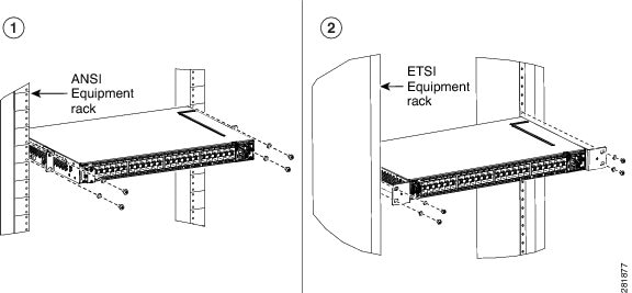
ANSI Rack Installation
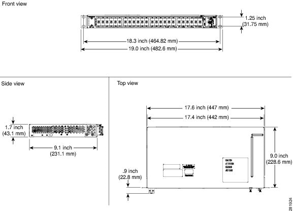
The CPT 50 shelf is mounted on a 19-inch (482.6-mm) or 23-inch (584.2-mm) equipment rack. If the shelf is mounted in the front position, then it projects 0.9 inches (22.86 mm) from the front of the rack. If the shelf assembly is mounted in the middle position, then it projects 4.3 inches (109.22 mm) from the front of the rack. The shelf mounts in both Electronic Industries Alliance (EIA) standard and Telcordia-standard racks. The shelf assembly is a total of 17.4 inches (442.4 mm) wide with no mounting ears attached. Ring runs are not provided by Cisco and might hinder side-by-side installation of shelves where space is limited.
The CPT 50 shelf measures 1.7 inches (43.1 mm) high, 19 or 23 inches (482.6 or 584.2 mm) wide (depending on which way the mounting ears are attached), and 9.1 inches (231.1 mm) deep.
The following figure shows the dimensions of the CPT 50 shelf in a 19-inch ANSI rack configuration with brackets mounted in the front position.
Mounting Brackets
Caution | Use only the fastening hardware provided with the CPT 50 shelf to prevent loosening, deterioration, and electromechanical corrosion of the hardware and joined material. |
Caution | When mounting the CPT 50 shelf in a frame with a nonconductive coating (such as paint, lacquer, or enamel) either use the thread-forming screws provided with the CPT 50 shelf shipping kit, or remove the coating from the threads to ensure electrical continuity. |
The mounting brackets (19-inch or 23-inch) are used to mount the shelf on a 19-inch (482.6 mm) rack or a 23-inch (584.2 mm) rack.
Mounting a Single Node
Mounting the CPT 50 shelf on a rack requires a minimum of 1.75 inches (44.44 mm) of vertical rack space. To ensure the mounting is secure, use two #12-24 mounting screws for each side of the shelf assembly. For an ANSI rack, the brackets can be mounted in the front or middle position.
ETSI Rack Installation
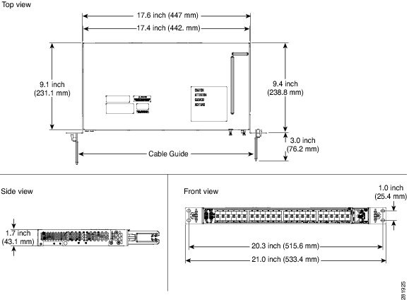
The CPT 50 shelf is mounted on a 600 x 600-mm (23.6 x 23.6-inch) or 600 x 300-mm (23.6 x 11.8-inch) ETSI standard equipment rack. The shelf assembly is a total of 442 mm (17.4 inches) wide with no mounting ears attached. Cisco does not provide ring runs, which might hinder side-by-side installation of shelves where space is limited.
The CPT 50 shelf measures 43.1 mm (1.7 inches) high, 533.4 mm (21 inches) wide, and 231.1 mm (9.1 inches) deep.
Figure 1 provides the dimensions of the CPT 50 shelf installed on a 600 x 600-mm (23.6 x 23.6-inch) ETSI standard equipment rack. In this figure, the cable guides are attached to the mounting brackets.
Caution | When mounting a shelf in a partially filled rack, load the rack from the bottom to the top with the heaviest component at the bottom of the rack. If the rack is provided with stabilizing devices, install the stabilizers before mounting or servicing the unit in the rack. |
Mounting a Single Node
The CPT 50 shelf requires 1.75 inches (44.44 mm) minimum of vertical rack space. To ensure the mounting is secure, use two M6 mounting screws for each side of the shelf assembly. In an ETSI rack, the brackets can be mounted only in the front position.
Wall Mounting and Desktop Mounting the CPT 50 Shelf
This section provides information about mounting the CPT 50 shelf on the wall and the desktop.
Wall Mounting
The CPT 50 shelf can be mounted on the wall using the wall mount brackets. The type of screws used to mount the brackets on the wall depends on the wall-type; wall mount brackets are not provided by Cisco.
After the CPT 50 shelf is mounted on the wall, a fire protective tray is installed on the wall mount bracket to support the shelf assembly.
Desktop Mounting
The CPT 50 shelf can be mounted on the desktop for easy access.
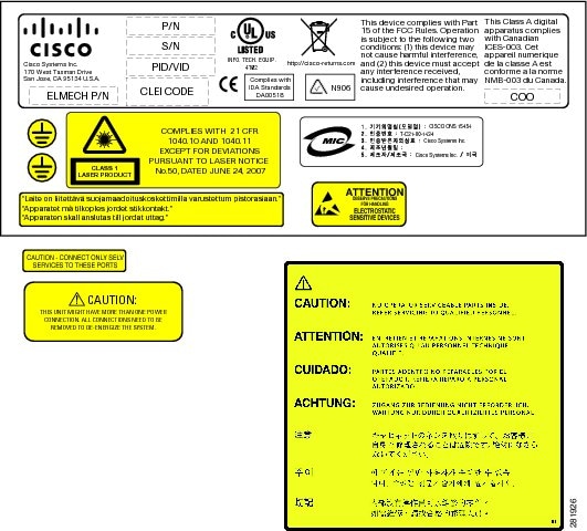
Laser Warning
The laser warning label is placed on top of the chassis. The following figure shows the label placed on the CPT 50 shelf.
NTP-J54 Install the CPT 50 Shelf
| Purpose | This procedure describes how to install the shelf. |
| Tools/Equipment |
|
| Prerequisite Procedures | NTP-J53 Unpack and Inspect the CPT 50 Shelf |
| Required/As Needed | Required |
| Onsite/Remote | Onsite |
| Security Level | None |
Note | In a CO (Central Office) or CPE (Customer Premises Equipment) installation, if the CPT 600 and CPT 50 units are connected through copper SFP+, place the units less than 6 meters apart in the same lineup. |
Warning | The intra-building ports of the equipment or subassembly is suitable for connection to intra-building or unexposed wiring or cabling only. The intra-building port(s) of the equipment or subassembly must not be metallically connected to interfaces that connect to the OSP or its wiring. These interfaces are designed for use as intra-building interfaces only (Type 2 or Type 4 ports as described in GR-1089-CORE) and require isolation from the exposed OSP cabling. The addition of Primary Protectors is not sufficient protection in order to connect these interfaces metallically to OSP wiring. Statement 7005 |
Warning | Stability hazard. The rack stabilizing mechanism must be in place, or the rack must be bolted to the floor before you slide the unit out for servicing. Failure to stabilize the rack can cause the rack to tip over. Statement 1048 |
Warning | This product requires short-circuit (overcurrent) protection, to be provided as part of the building installation. Install only in accordance with national and local wiring regulations. Statement 1045 |
Warning | This product relies on the building’s installation for short-circuit (overcurrent) protection. Ensure that the protective device is rated not greater than: 10A for CPT 50 shelf with 48 VDC power supply; 15A for CPT 50 shelf with 24 VDC power supply. Statement 1005 |
Warning | This product relies on the building's installation for short-circuit (overcurrent) protection. Ensure that the protective device is rated not greater than: 10A-15A, 100-240VAC~. Statement 1005 |
Warning | To prevent the system from overheating, do not operate it in an area that exceeds the maximum recommended ambient temperature of: 131°F (55°C) for CPT 50 shelf with AC power module and 149°F (65°C) for CPT 50 shelf with DC power module. Statement 1047 |
Warning | Take care when connecting units to the supply circuit so that wiring is not overloaded. Statement 1018 |
Warning | To prevent bodily injury when mounting or servicing this unit in a rack, you must take special precautions to ensure that the system remains stable. The following guidelines are provided to ensure your safety:
|
Warning | To prevent airflow restriction, allow clearance around the ventilation openings to be at least: 1 inch (25.4 mm). Statement 1076 |
Warning | To pass Electrical Fast Transient/Burst (EFT/B) for GR-1089, the Westek UL C(UL) E171740 Type CM 24AWG 75degC EIA/TIA 568-B.2 STP CAT5e dual bantam to RJ45 shielded cable or an equivalent must be used with the DS1 pluggable 30-1462-01. The cable must have a grounded wire that is connected to the RJ45 shell as well as a shield of an aluminum foil. |
Note | The CPT 50 installations are suitable for Network Telecommunication facilities and locations where NEC applies. |
| Step 1 | Complete the
necessary task as applicable:
|
| Step 2 | Complete the
necessary mounting task as applicable:
|
| Step 3 | Connect the
chassis to the office ground. For detailed instructions on how to ground the
chassis, see the
Electrostatic
Discharge and Grounding Guide for Cisco CPT and Cisco ONS Platforms.
Stop. You have completed this procedure. |
DLP-J173 Mounting the 19-inch Brackets on the CPT 50 Shelf for the ANSI Rack Configuration
| Purpose | This task describes how to install the 19-inch mounting brackets on the CPT 50 shelf for the ANSI rack configuration. |
| Tools/Equipment | |
| Prerequisite Procedures | NTP-J53 Unpack and Inspect the CPT 50 Shelf |
| Required/As Needed | As Needed |
| Onsite/Remote | Onsite |
| Security Level | None |
Caution | Use only the fastening hardware provided with the CPT 50 shelf to prevent loosening, deterioration, and electromechanical corrosion of the hardware and joined material. |
Caution | When mounting the CPT 50 shelf in a frame with a nonconductive coating (such as paint, lacquer, or enamel) either use the thread-forming screws provided with the CPT 50 ship kit, or remove the coating from the threads to ensure electrical continuity. |
Note | The mounting brackets can be installed in the front or the middle position of the chassis. |
| Step 1 | Place the wider side of the 19-inch mounting bracket flush against the CPT 50 shelf, as shown in Figure 1. The narrow side of the mounting bracket should be towards the front of the shelf. |
| Step 2 | Align the mounting bracket screw holes against the shelf assembly screw holes. |
| Step 3 | Insert the M4 flat screws and tighten them to a torque value of 11.5 in-lbs (1.3 N-m). |
| Step 4 | Repeat Step 1 to Step 3 to mount the bracket on the opposite side. 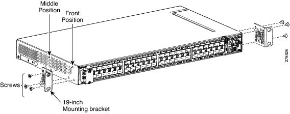 |
| Step 5 | Return to your originating procedure (NTP). |
DLP-J174 Mounting the 23-inch Brackets on the CPT 50 Shelf for the ANSI Rack Configuration
| Purpose | This task describes how to install the 23-inch mounting brackets on the CPT 50 shelf for the ANSI rack configuration. |
| Tools/Equipment | |
| Prerequisite Procedures | NTP-J53 Unpack and Inspect the CPT 50 Shelf |
| Required/As Needed | As Needed |
| Onsite/Remote | Onsite |
| Security Level | None |
Caution | Use only the fastening hardware provided with the CPT 50 shelf to prevent loosening, deterioration, and electromechanical corrosion of the hardware and joined material. |
Caution | When mounting the CPT 50 shelf in a frame with a nonconductive coating (such as paint, lacquer, or enamel) either use the thread-forming screws provided with the CPT 50 ship kit, or remove the coating from the threads to ensure electrical continuity. |
Note | The mounting brackets can be installed in the front or the middle position of the chassis. |
| Step 1 | Place the narrow side of the 23-inch mounting bracket flush against the CPT 50 shelf, as shown in Figure 1. The wider side of the mounting bracket should be towards the front of the shelf. | ||
| Step 2 | Align the mounting bracket screw holes against the shelf assembly screw holes. | ||
| Step 3 | Insert the M4 flat screws and tighten them to a torque value of 11.5 in-lbs (1.3 N-m). | ||
| Step 4 | Repeat Step 1 to Step 3 to mount the bracket on the opposite side. 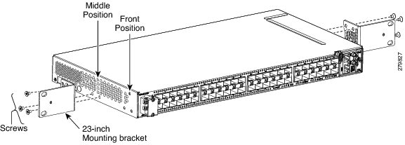 | ||
| Step 5 | Align the cable guide screw hole against the mount bracket screw hole, as shown in this figure. 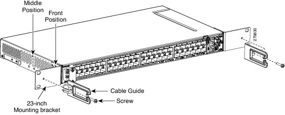 | ||
| Step 6 | Insert the M4 screw and tighten it to a torque value of 6.5 in-lbs (0.75 N-m) .
| ||
| Step 7 | Repeat Step 5 and Step 6 to install the cable guide on the opposite side. | ||
| Step 8 | Return to your originating procedure (NTP). |
DLP-J175 Mounting the Brackets on the CPT 50 Shelf for the ETSI Rack Configuration
| Purpose | This task describes how to install the mounting brackets on the CPT 50 shelf for the ETSI rack configuration. |
| Tools/Equipment | |
| Prerequisite Procedures | NTP-J53 Unpack and Inspect the CPT 50 Shelf |
| Required/As Needed | As Needed |
| Onsite/Remote | Onsite |
| Security Level | None |
Caution | Use only the fastening hardware provided with the CPT 50 shelf to prevent loosening, deterioration, and electromechanical corrosion of the hardware and joined material. |
Caution | When mounting the CPT 50 shelf in a frame with a nonconductive coating (such as paint, lacquer, or enamel) either use the thread-forming screws provided with the CPT-50 ship kit, or remove the coating from the threads to ensure electrical continuity. |
Note | The mounting brackets can be installed in the front or the middle position of the chassis. |
| Step 1 | Place the mounting bracket flush against the CPT 50 shelf, as shown in this figure. 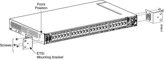 | ||
| Step 2 | Align the mounting bracket screw holes against the CPT 50 shelf screw holes. | ||
| Step 3 | Insert the M4 flat screws and tighten them to a torque value of 11.5 in-lbs (1.3 N-m). | ||
| Step 4 | Repeat Step 1 to Step 3 to mount the bracket on the opposite side. | ||
| Step 5 | Align the cable guide screw hole against the mount bracket screw hole, as shown in this figure. 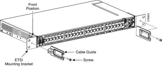 | ||
| Step 6 | Insert the M4 screw and tighten it to a torque value of 6.5 in-lbs (0.75 N-m) .
| ||
| Step 7 | Repeat Step 5 and Step 6 to install the cable guide on the opposite side. | ||
| Step 8 | Return to your originating procedure (NTP). |
DLP-J176 Mount the CPT 50 Shelf on a Rack (One Person)
| Purpose | This task explains how one person can mount the shelf assembly in a rack. |
| Tools/Equipment | |
| Prerequisite Procedures | NTP-J53 Unpack and Inspect the CPT 50 Shelf |
| Required/As Needed | As Needed |
| Onsite/Remote | Onsite |
| Security Level | None |
Note | The CPT 50 shelf requires a minimum of 1.75 inches (44.44 mm) of vertical rack space. To ensure that the mounting is secure, use two M6 mounting screws on each side of the shelf for ETSI rack installation, and two 12-24 x 3/4 pan-head Phillips mounting screws on each side of the shelf for ANSI rack installation. A shelf assembly should be mounted at the bottom of the rack if it is the only unit in the rack. |
Note | In an ANSI rack, the chassis can be installed in the front or the middle position. In an ETSI rack, the chassis can be installed only in the front position. |
| Step 1 | Verify that the proper fuse panel has been installed in the top mounting space. If a fuse panel is not present, you must install one according to manufacturer instructions:
|
| Step 2 |
Ensure that the shelf assembly is mounted on the appropriate rack equipment:
 |
| Step 3 | Lift the shelf to the desired position in the rack. |
| Step 4 | Align the screw holes on the mounting brackets with the mounting holes in the rack. |
| Step 5 | Using the Phillips Dynamometric screwdriver, install one mounting screw in each side of the assembly: |
| Step 6 | When the shelf assembly is secured to the rack, install the remaining two mounting screws on either sides of the shelf assembly. |
| Step 7 | Return to your originating procedure (NTP). |
DLP-J177 Mount the CPT 50 Shelf on the Wall
| Purpose | This task explains how to mount the CPT 50 shelf on the wall. |
| Tools/Equipment | |
| Prerequisite Procedures | NTP-J53 Unpack and Inspect the CPT 50 Shelf |
| Required/As Needed | As Needed |
| Onsite/Remote | Onsite |
| Security Level | None |
Note | The CPT 50 shelf requires a minimum of 23.65 inches (600-mm) vertical length and a minimum of 15.75 inches (400-mm) horizontal width on the wall. Wall mount brackets are used to mount the CPT 50 shelf on the wall. The type of screws used to mount the brackets on the wall depends on the wall-type; wall mount brackets are not provided by Cisco. The screws used must be able to sustain an overall weight of at least 10 kg (22 lb). |
| Step 1 | Verify that the proper fuse panel has been installed in the top mounting space. If a fuse panel is not present, you must install one according to manufacturer instructions:
|
| Step 2 | Mount the bracket on the wall, as shown in Figure 1. To mount the bracket on a non-concrete wall, choose the bracket holes based on the wall structure. At least four screws must be used to mount the bracket on the wall. Based on the wall material, apply the torque value provided by the screw vendor. |
| Step 3 | Align the mounting bracket screw holes against the shelf screw holes, as shown in diagram 1 of Figure 1. |
| Step 4 | Insert six M4 pan-head screws and tighten them to a torque value of 11.5 in-lbs (1.3 N-m), as shown in diagram 2 of Figure 1. 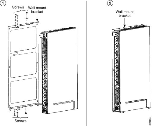 |
| Step 5 | Align the fire protective drip tray screw holes against the wall mounting bracket screw holes, as shown in diagram 1 of Figure 2. The fire protective drip tray is present in the wall mount accessory kit provided by Cisco. The part number of the fire protective drip tray is Cisco PN 700-31762-XX. The product identifier (PID) of the wall mount accessory kit is CPT-50-BRKTWM= and the part number is Cisco PN 53-3513-XX. |
| Step 6 | Insert two M4 pan-head screws and tighten them to a torque value of 11.5 in-lbs (1.3 N-m), as shown in diagram 2 of Figure 2. 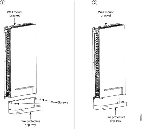 |
| Step 7 | Return to your originating procedure (NTP). |
DLP-J178 Mount the CPT 50 Shelf on the Desktop
| Purpose | This task explains how to mount the shelf on the desktop. |
| Tools/Equipment | |
| Prerequisite Procedures | NTP-J53 Unpack and Inspect the CPT 50 Shelf |
| Required/As Needed | As Needed |
| Onsite/Remote | Onsite |
| Security Level | None |
| Step 1 | Verify that the proper fuse panel has been installed in the top mounting space. If a fuse panel is not present, you must install one according to manufacturer instructions:
|
| Step 2 | Locate the rubber bumpers provided in the accessory tool kit. |
| Step 3 | Place the CPT 50 shelf upside down on a smooth, flat surface. |
| Step 4 | Peel off the rubber bumpers from the adhesive strip and place it adhesive-side down onto all the four corners of the surface, as shown in this figure. 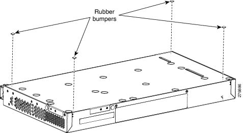 |
| Step 5 | Place the CPT 50 shelf on a desktop, or other flat and secure surface. |
| Step 6 | Return to your originating procedure (NTP). |
Power Module
Note | Do not remove the top cover of the CPT 50 shelf. |
CPT 50 Shelf with an AC Power Module
The AC power module converts the AC input current to DC output current. The AC power module has one AC single phase with 3- pole ( line L, Neutral N, and Protective Earth PE) input connector.
CPT 50 Shelf with a DC Power Module
The CPT 50 shelf with a DC power module can be powered by redundant DC power lines, however a single power line can power the entire CPT 50 shelf.
The CPT 50 shelf with DC power module for ETSI standard has two input battery connectors (two poles)— –48V, RET for power terminals A and B.
The CPT 50 shelf with DC power module for ANSI standard has single terminal block with four poles— –48V, RET for power terminals A and B.
Fan-Tray Assembly
The fan-tray assembly is preinstalled on the right side of the CPT 50 shelf. The fan-tray assembly is removable and holds fans and fan-control circuitry for the CPT 50 shelf. The fan-tray assembly should be accessed only if a fan failure occurs.
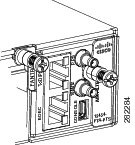
EOBC (Ethernet Out-of-Band Channel)—An RJ-45 port that supports high bandwidth external connectivity. If the CPT-50 shelf fails to boot up, the EOBC port also called as the disaster recovery port is used to log in to the CPT-50 shelf for troubleshooting.
Note
The EOBC port is meant only for TAC (Technical Assistance Center) usage.PPS (Pulse Per Second)—A mini BNC output port that provides timing signals to an external equipment from the CPT 50 shelf .
10MH—A mini BNC output port that provides timing signals at a frequency of 10 MHz to an external equipment from the CPT 50 shelf and RET for power terminals A and B.
ToD/PPS (Time of Day/Pulse Per Second)—An RJ-45 serial output port that provides time and day information and timing signals to an external equipment from the CPT 50 shelf.
CONSOLE—A USB port that is used to connect a console terminal. The console terminal can be one of the following:
Note | The timing signals are compliant with the IEEE 1588 standard. |
The console port provides access to the CPT 50 shelf either locally (using a console terminal), or remotely (using a modem). Console connections transmit at slower speeds than modems; therefore, the console connection is suited for use with console terminals.
Note | An RJ-45 serial port is used for TOD/PPS functionality. The two RJ-45 pins 7 and 8 is used for TOD (Time Of Day) functionality and the other two RJ-45 pins 1 and 2 are used for PPS functionality. Even though an RJ-45 cable is used for TOD/PPS connection, a serial link is established. Two mini coax connectors with RG316 1.0/2.3 M/M cables (50 ohm) are used for PPS (Pulse Per Second) and for 10MHz sinusoidal signal. Cable for TOD/PPS and 10MHz shall be shielded. |
Note | For rules about provisioning timing references, see Telcordia SR-NWT-002224. |
Fan Speed
Fan speed is controlled by the microprocessor present in the CPT 50 shelf. The sensors measure the critical component temperature of the CPT 50 shelf. Fan speed options are low, medium, and high.
Fan Failure
If one or more fans fail on the fan-tray assembly, replace the entire assembly. You cannot replace individual fans. The red Fan Fail LED on the front of the CPT 50 shelf illuminates when one or more fans fail. The red Fan Fail LED clears after you install a working fan-tray.
NTP-J55 Replace the Fan-Tray Assembly in the CPT 50 Shelf
| Purpose | This procedure describes how to replace the fan-tray assembly in the CPT 50 shelf. |
| Tools/Equipment | #2 Phillips Dynamometric screwdriver |
| Prerequisite Procedures | |
| Required/As Needed | Required |
| Onsite/Remote | Onsite |
| Security Level | None |
Caution | Do not operate an CPT 50 shelf without an air filter. |
Note | The estimated time for a skilled technician to replace an equipment fan or fan tray is 2 minutes. |
Note | The fan or the cooling unit can be replaced without service interruption. |
Caution | Do not force a fan-tray module into place. Doing so can damage either the connectors on the fan tray or the connectors on the back panel of the shelf assembly, or both. |
Note | Error messages appear on the TNC or TSC card, the fan-tray LED, and in Cisco Transport Controller (CTC) when the fan-tray module is removed from the shelf or when one fan is not working. |
| Step 1 | Loosen the screw on the fan-tray assembly, as shown in this figure. 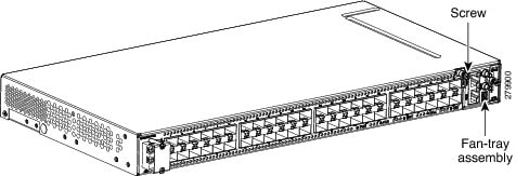 |
| Step 2 | Extract the fan-tray assembly partially ( not more than 1 inch) to disconnect the backplane connector and wait until the fan stops. |
| Step 3 | When the fans have stopped, pull the fan-tray assembly completely out of the shelf, as shown this figure. 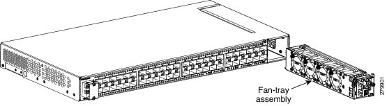 |
| Step 4 | Slide the new fan-tray assembly into the shelf until the electrical plug at the rear of the tray plugs into the corresponding receptacle on the backplane. |
| Step 5 | Tighten the M3 screw to a torque value of 4 in-lbs (0.45 N-m) on the fan-tray assembly. Stop. You have completed this procedure. |
NTP-J56 Replace the Air Filter in the CPT 50 Shelf
| Purpose | This procedure explains how to replace the air filter of the CPT 50 shelf. |
| Tools/Equipment | #2 Phillips Dynamometric screwdriver |
| Prerequisite Procedures | |
| Required/As Needed | Required |
| Onsite/Remote | Onsite |
| Security Level | None |
Caution | Do not operate a CPT 50 shelf without an air filter. |
Note | Replacement or cleaning of an air filter is recommended every 60 days. Air filters are replaceable or reusable. |
| Step 1 | Loosen the screw on the air filter faceplate, as shown in this figure. 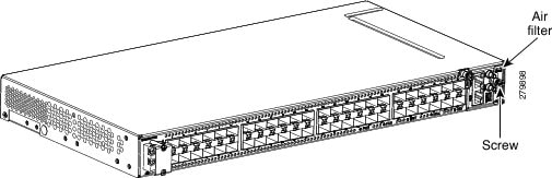 |
| Step 2 | Extract the air filter from the shelf, as shown in this figure. 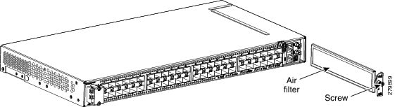 |
| Step 3 | Remove the air filter faceplate from the air filter frame, as shown in this figure. 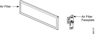 |
| Step 4 | Clean or replace the air filter. |
| Step 5 | Insert the air filter faceplate engaging the air filter frame, as shown in this figure. 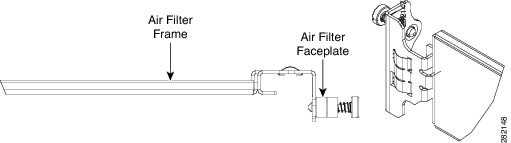 |
| Step 6 | Insert the air filter into the shelf. |
| Step 7 | Tighten the M3 screw to a torque value of 4.0 in-lbs (0.45 N-m) on the air-filter. Stop. You have completed this procedure. |
Power and Ground Description
Note | For detailed instructions on grounding the CPT 50 shelf, refer to the Electrostatic Discharge and Grounding Guide for Cisco CPT and Cisco ONS Platforms. |
ANSI Power and Ground
For AC power feed, use the power cable shipped with the CPT 50 shelf. For an AC power supply, the fuse rating must not exceed 10 A or 15 A, depending on the standards in various countries. The overcurrent and short circuit protection must be in accordance with local and national electrical codes. The voltage rating value for AC power ranges between 100 VAC to 240 VAC depending on the standards in various countries. This product is intended for use on the TN and TT power systems.
The CPT 50 shelf for 48 VDC power supply has redundant –48 VDC #14 single-hole lug power terminals. The terminals are labeled RET(A), RET(B), -48V(A), and -48V(B) on the power module. See the figure below:
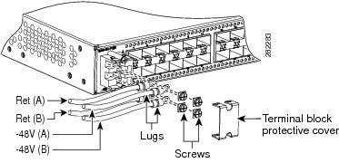
The CPT 50 shelf for 24 VDC power supply has redundant –24 VDC #14 single-hole lug power terminals. The terminals are labeled RET(A), RET(B), -24V(A), and -24V(B) on the power module.
To install redundant DC power feeds, use four power cables and one ground cable. For a single power feed, only two power cables (#14 AWG or larger, copper conductor, 194 degrees Fahrenheit [90 degrees Celsius] minimum) and one ground cable (#8 AWG or larger) are required. Use a conductor with low impedance to ensure circuit overcurrent protection. However, the conductor must have the capability to safely conduct any faulty current that might be imposed.
For a 24 VDC power supply, the fuse rating must not exceed 15 A. The voltages –20 VDC and –28.3 VDC are, respectively, the minimum and maximum voltages required to power the chassis. The nominal steady state voltage is -24 VDC.
For a 48 VDC power supply, the fuse rating must not exceed 10 A. The voltages –40.5 VDC and –57.6 VDC are, respectively, the minimum and maximum voltages required to power the chassis. Functionality is guaranteed at -40 VDC input voltage, according to GR-1089. The nominal steady state voltage is -48 VDC.
The ground lug must be a dual-hole type, UL Listed, CSA certified, and rated to accept the #8 AWG cable. Two ground threaded holes with M4 screws are provided on the CPT 50 shelf to accommodate the dual-hole lug. See the figure below:
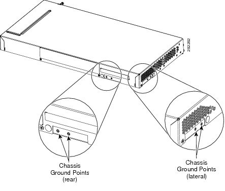
ETSI Power and Ground
The CPT 50 shelf for ETSI has redundant –48 VDC power connectors (DSUB for DC power module) on the DC power module. To install redundant power feeds, use the two power cables shipped with the CPT 50 shelf and one ground cable. For a DC power supply, the fuse rating must not exceed 10 A. The voltages –40.5 VDC and –57.6 VDC are, respectively, the minimum and maximum voltages required to power the chassis. The nominal steady state voltage is -48 VDC.
For AC power feed, use the power cable shipped with the CPT 50 shelf. For an AC power supply, the fuse rating must not exceed 10 A or 15 A, depending on the standards in various countries. The overcurrent and short circuit protection must be in accordance with local and national electrical codes. The voltage rating value for AC power ranges between 100 VAC to 240 VAC depending on the standards in various countries. This product is intended for use on the TN and TT power systems.
Caution | Use only the power cables shipped with the CPT 50 shelf. The part number of the cables is Cisco PN 72-4974-XX and the PID is CPT-DC-CBL-E=. |
NTP-J57 Install the Power Feeds and Ground to the CPT 50 Shelf
| Purpose | This procedure explains how to install power feeds and ground the CPT 50 shelf. |
| Tools/Equipment | ANSI and ETSI: |
| Prerequisite Procedures | Connect the chassis to the office ground. For detailed instructions on how to ground the chassis, see the Electrostatic Discharge and Grounding Guide for Cisco CPT and Cisco ONS Platforms. |
| Required/As Needed | Required |
| Onsite/Remote | Onsite |
| Security Level | None |
Warning | This equipment must be grounded. Never defeat the ground conductor or operate the equipment in the absence of a suitably installed ground conductor. Contact the appropriate electrical inspection authority or an electrician if you are uncertain that suitable grounding is available. Statement 1024 |
Warning | To reduce the risk of electric shock, switch on the power only after the power cord is completely installed into the power module. Statement 390 |
Warning | When stranded wiring is required, use approved wiring terminations, such as closed-loop or spade-type with upturned lugs. These terminations should be the appropriate size for the wires and should clamp both the insulation and conductor. Statement 1002 |
Warning | Before performing any of the following procedures, ensure that power is removed from the DC circuit. Statement 1003 |
Warning | Before working on a chassis or working near power supplies, unplug the power cord on AC units. Statement 246 |
Warning | This equipment is intended to be grounded. Ensure that the host is connected to earth ground during normal use. Statement 39 |
Warning | Use copper conductors only. Statement 1025 |
Warning | Connect the unit only to DC power source that complies with the safety extra-low voltage (SELV) requirements in IEC 60950-1 based safety standards. Statement 1033 |
Warning | This product requires short-circuit (overcurrent) protection, to be provided as part of the building installation. Install only in accordance with national and local wiring regulations. Statement 1045 |
Warning | This product relies on the building’s installation for short-circuit (overcurrent) protection. Ensure that the protective device is rated not greater than: 10A for CPT 50 shelf with 48 VDC power supply; 15A for CPT 50 shelf with 24 VDC power supply. Statement 1005 |
Warning | This product relies on the building's installation for short-circuit (overcurrent) protection. Ensure that the protective device is rated not greater than: 10A-15A, 100-240VAC~. Statement 1005 |
Warning | A readily accessible two-poled disconnect device must be incorporated in the fixed wiring. Statement 1022 |
Warning | This unit might have more than one power supply connection. All connections must be removed to de-energize the unit. Statement 1028 |
Caution | Always use the supplied ESD wristband when working with a powered CPT 50 shelf. For detailed instructions on how to wear the ESD wristband, see the Electrostatic Discharge and Grounding Guide for Cisco CPT and Cisco ONS Platforms. |
| Step 1 | Verify that the correct fuse panel is installed in the top mounting space:
|
| Step 2 |
Depending on the shelf and the power module installed, complete the necessary task: |
| Step 3 | Connect the office ground to the CPT 50 shelf. For detailed instructions on grounding, refer to the Electrostatic Discharge and Grounding Guide for Cisco CPT and Cisco ONS Platforms. |
| Step 4 | Complete the DLP-J182 Turn On and Verify AC Office Power on the CPT 50 Shelf or DLP-J183 Turn On and Verify DC Office Power on the CPT 50 Shelf as necessary. Stop. You have completed this procedure. |
DLP-J179 Connect Office Power (AC) to the CPT 50 Shelf
| Purpose | This task explains how to connect AC power to the CPT 50 shelf. |
| Tools/Equipment | |
| Prerequisite Procedures | |
| Required/As Needed | Required |
| Onsite/Remote | Onsite |
| Security Level | None |
Note | This product is intended for use on the TN and TT power systems. |
Warning | When installing or replacing the unit, the ground connection must always be made first and disconnected last. Statement 1046 |
Warning | This equipment shall be connected to AC mains provided with a surge protective device (SPD) at the service equipment complying with NFPA 70, the National Electrical Code (NEC). Statement 7012 |
Caution | The CPT 50 shelf relies on the protective devices in the building installation to protect against short circuit, overcurrent, and ground faults. Ensure that the protective devices are properly rated and comply with national and local codes. |
Caution | When terminating the frame ground, do not use soldering lug connectors, screwless (push-in) connectors, quick connect connectors, or other friction-fit connectors. |
Note | If the CPT-50 shelf loses its connection to the line or fabric card, the CPT-50 shelf resets until the connection to the line or fabric card is re-established. |
| Step 1 | Attach the AC power cable to the cable connector in the AC power module, as shown in this figure. 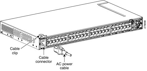 | ||
| Step 2 | Close the cable clip to secure the power cable, as shown in this figure. 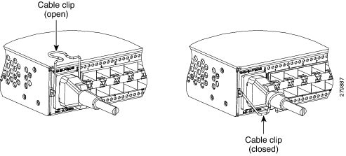 | ||
| Step 3 | Connect the power cable to the fuse panel or power source.
| ||
| Step 4 | Return to your originating procedure (NTP). |
DLP-J180 Connect Office Power (DC) to the CPT 50 Shelf (ANSI Only)
| Purpose | This task explains how to connect the DC power to the CPT 50 shelf (ANSI Only). |
| Tools/Equipment |
|
| Prerequisite Procedures |
|
| Required/As Needed | Required |
| Onsite/Remote | Onsite |
| Security Level | None |
Warning | When installing or replacing the unit, the ground connection must always be made first and disconnected last. Statement 1046 |
Warning | Hazardous voltage or energy may be present on DC power terminals. Always replace cover when terminals are not in service. Be sure uninsulated conductors are not accessible when cover is in place. Statement 1075 |
Caution | The CPT 50 shelf relies on the protective devices in the building installation to protect against short circuit, overcurrent, and ground faults. Ensure that the protective devices are properly rated and comply with national and local codes. |
Note | The battery return connection is treated as DC-I, as defined in Telcordia GR-1089-CORE. |
Note | If the CPT-50 shelf loses its connection to the line or fabric card, the CPT-50 shelf resets until the connection to the line or fabric card is re-established. |
| Step 1 | Connect the return cables of the power supply to the Earth ground located at the power supply side. | ||||||
| Step 2 | Connect the office power according to the fuse panel engineering specifications. | ||||||
| Step 3 | Measure and cut the cables as needed to reach the CPT 50 shelf from the fuse panel. | ||||||
| Step 4 | Dress the power according to local site practice. | ||||||
| Step 5 | Strip 1/2 inch (12.7 mm) of insulation from all power cables that you will use. | ||||||
| Step 6 | Crimp the lugs onto the ends of all the power leads. | ||||||
| Step 7 | Remove the
terminal block protective cover, as shown in this figure.
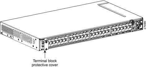
| ||||||
| Step 8 | Untighten the
terminal block screws, as shown in this figure.
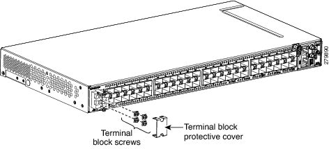
| ||||||
| Step 9 | Insert the lugs,
as shown in this figure.
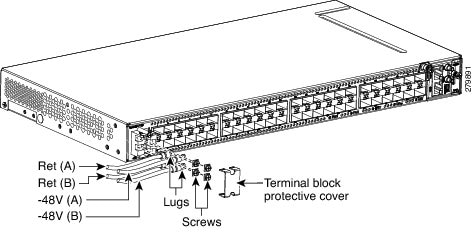
| ||||||
| Step 10 | Tighten the M3.5 screws to a torque value of 7 in-lbs (0.79 N-m) to lock the lugs. | ||||||
| Step 11 | Mount the terminal
block protective cover on the CPT 50 shelf (see the following figure,
"Connecting Office Power—DC Power Modules (ANSI Only)").
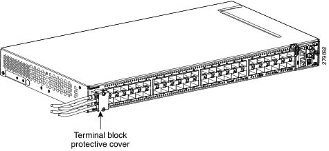
| ||||||
| Step 12 | Return to your originating procedure (NTP). |
DLP-J181 Connect Office Power (DC) to the CPT 50 Shelf (ETSI Only)
| Purpose | This task explains how to connect the DC power to the CPT 50 shelf (ETSI Only). |
| Tools/Equipment | |
| Prerequisite Procedures |
|
| Required/As Needed | Required |
| Onsite/Remote | Onsite |
| Security Level | None |
Warning | When installing or replacing the unit, the ground connection must always be made first and disconnected last. Statement 1046 |
Warning | Hazardous voltage or energy may be present on DC power terminals. Always replace cover when terminals are not in service. Be sure uninsulated conductors are not accessible when cover is in place. Statement 1075 |
Note | The battery return connection is treated as DC-I, as defined in Telcordia GR-1089-CORE. |
Caution | The CPT 50 shelf relies on the protective devices in the building installation to protect against short circuit, overcurrent, and ground faults. Ensure that the protective devices are properly rated and comply with national and local codes. |
Note | If the CPT 50 shelf loses its connection to the line or fabric card, the CPT 50 shelf resets until the connection to the line or fabric card is re-established. |
| Step 1 | Connect the return cables of the power supply to the Earth ground located at the power supply side. | ||||||
| Step 2 | Attach the DC ETSI
power cables to the DSUB power connectors of the DC power module, as shown in
this figure.
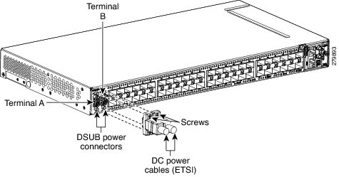
| ||||||
| Step 3 | Tighten the M3
pan-head screws to a torque value of 4 in-lbs ( 0.45 N-m) to secure the cable,
as shown in this figure.

| ||||||
| Step 4 | Return to your originating procedure (NTP). |
DLP-J182 Turn On and Verify AC Office Power on the CPT 50 Shelf
| Purpose | This task explains how to measure the power to verify correct power and returns for the CPT 50 shelf. |
| Tools/Equipment | Voltmeter |
| Prerequisite Procedures | |
| Required/As Needed | Required |
| Onsite/Remote | Onsite |
| Security Level | None |
Warning | To reduce the risk of electric shock, switch on the power only after the power cord is completely installed into the power module. Statement 390 |
Caution | Do not apply power to the shelf assembly until you complete all the installation steps. |
| Step 1 | To power up the node, insert the fuse into the fuse position according to site practice. For an AC power supply, the fuse rating must not exceed 10 A or 15 A, depending on the standards in various countries. |
| Step 2 | If the CPT 50 shelf does not power up, check the voltage at the power source using a voltmeter. The voltage should be 100 VAC to 240 VAC +/-10 percent. |
| Step 3 | Return to your originating procedure (NTP). |
DLP-J183 Turn On and Verify DC Office Power on the CPT 50 Shelf
| Purpose | This task explains how to measure the power to verify correct power and returns for the CPT 50 shelf. |
| Tools/Equipment | Voltmeter |
| Prerequisite Procedures |
|
| Required/As Needed | Required |
| Onsite/Remote | Onsite |
| Security Level | None |
Warning | To reduce the risk of electric shock, switch on the power only after the power cord is completely installed into the power module. Statement 390 |
Caution | Do not apply power to the shelf assembly until you complete all the installation steps. |
| Step 1 | Using a voltmeter, verify the office battery and ground at the following points on the fuse panel: |
| Step 2 | To power up the node, insert the fuse into the fuse position according to site practice. For a 24 VDC power supply, the fuse rating must not exceed 15 A. For a 48V DC power supply, the fuse rating must not exceed 10 A. |
| Step 3 | Using a voltmeter, verify the CPT 50 shelf for –48 VDC or –24 VDC battery and return: |
| Step 4 | Return to your originating procedure (NTP). |
NTP-J58 Connecting Cables to the EOBC, Timing, and Console Ports
| Purpose | This procedure describes how to connect cables to the EOBC, timing, and console ports in the CPT 50 shelf. |
| Tools/Equipment | |
| Prerequisite Procedures | |
| Required/As Needed | As needed |
| Onsite/Remote | Onsite |
| Security Level | None |
Caution | Always use the supplied Electrostatic Discharge (ESD) wristband when working with a powered CPT 50 shelf. For detailed instructions on how to wear the ESD wristband, see the Electrostatic Discharge and Grounding Guide for Cisco CPT and Cisco ONS Platforms. |
| Step 1 | Complete the DLP-J184 Connect the Timing Cables to the PPS, 10MHz, and ToD/PPS Ports to connect timing to an external equipment. |
| Step 2 | Complete the DLP-J185 Install Cables to the EOBC or Console Port to install the cables to the EOBC or console port. Stop. You have completed this procedure. |
DLP-J184 Connect the Timing Cables to the PPS, 10MHz, and ToD/PPS Ports
| Purpose | This procedure describes how to connect the timing cables to the PPS, 10 MHz, and ToD/PPS ports on the CPT 50 shelf. |
| Tools/Equipment | |
| Prerequisite Procedures | |
| Required/As Needed | As needed |
| Onsite/Remote | Onsite |
| Security Level | None |
Warning | The intra-building ports of the equipment or subassembly is suitable for connection to intra-building or unexposed wiring or cabling only. The intra-building port(s) of the equipment or subassembly must not be metallically connected to interfaces that connect to the OSP or its wiring. These interfaces are designed for use as intra-building interfaces only (Type 2 or Type 4 ports as described in GR-1089-CORE) and require isolation from the exposed OSP cabling. The addition of Primary Protectors is not sufficient protection in order to connect these interfaces metallically to OSP wiring. Statement 7005 |
Note | For rules about provisioning timing references, see ITU-T G.813. |
Note | To unplug the RJ-45 cables connected to the ToD/PPS and EOBC ports on the fan-tray, use small pliers or a screwdriver. |
| Step 1 | Locate the timing
connectors (PPS, 10 MHz, or ToD/PPS) on the fan-tray assembly of the CPT 50
shelf, as shown in this figure.
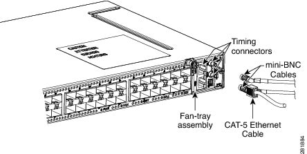
|
| Step 2 | To connect the PPS or 10 MHz port: |
| Step 3 | To connect the ToD/PPS RJ-45 output port: |
| Step 4 | Return to your originating procedure (NTP). |
DLP-J185 Install Cables to the EOBC or Console Port
| Purpose | This procedure explains how to connect cables to the EOBC or console port on the CPT 50 shelf. |
| Tools/Equipment | |
| Prerequisite Procedures | |
| Required/As Needed | As needed |
| Onsite/Remote | Onsite |
| Security Level | None |
Warning | The intra-building ports of the equipment or subassembly is suitable for connection to intra-building or unexposed wiring or cabling only. The intra-building port(s) of the equipment or subassembly must not be metallically connected to interfaces that connect to the OSP or its wiring. These interfaces are designed for use as intra-building interfaces only (Type 2 or Type 4 ports as described in GR-1089-CORE) and require isolation from the exposed OSP cabling. The addition of Primary Protectors is not sufficient protection in order to connect these interfaces metallically to OSP wiring. Statement 7005. |
Note | The console port is used for the setup and maintenance of the CPT 50 shelf and the EOBC port is used for disaster recovery, that is, to log in to the CPT 50 shelf for troubleshooting when the connection between the CPT 50 shelf and CPT 600 shelf is lost. |
Note | To unplug the RJ-45 cables connected to the ToD/PPS and EOBC ports on the fan-tray, use small pliers or a screwdriver. |
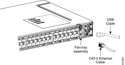
NTP-J59 Install and Route Fiber-Optic Cables
| Purpose | This task describes how to install and route fiber-optic cables. |
| Tools/Equipment | |
| Prerequisite Procedures | None |
| Required/As Needed | Required |
| Onsite/Remote | Onsite |
| Security Level | None |
Warning | Invisible laser radiation may be emitted from disconnected fibers or connectors. Do not stare into beams or view directly with optical instruments. Statement 1051 |
Caution | When connecting an optical fiber patch cord between the CPT 50 shelf and the optical card ports in the Cisco ONS 15454 M6 or Cisco ONS 15454 M2, use the electrostatic discharge wristband supplied with the Cisco ONS 15454 M6 or M2. |
Note | Always clean all the fiber connectors thoroughly before making the connection with the mating adapter. Very small particles can permanently damage the end of the mating fiber inside the CPT 50 shelf, which makes regular cleaning imperative. For cleaning instructions, see NTP-J60 Clean Fiber Connectors. |
Note | The CPT 50 shelf features LC/UPC bulkhead adapters. Always use fiber-optic cables equipped with the corresponding (LC/UPC) connector type. Using any other type of connector results in damage to the connector or adapter, or both. |
| Step 1 | Place the LC/UPC cable connector in front of the corresponding bulkhead adapter on the front panel of the CPT 50 shelf. | ||
| Step 2 | Align the keyed ridge of the cable connector with the slot in the receiving adapter. | ||
| Step 3 | Gently push the cable connector into the adapter until you hear a click, which indicates that the latching system is engaged. | ||
| Step 4 | Route the fiber cables through the cable guide (left and right side). A tie-wrap is tied around the fiber and cables through the cable guide. The cables are routed through the cable guide in an ANSI (23-inch) rack configuration, as shown in this figure. 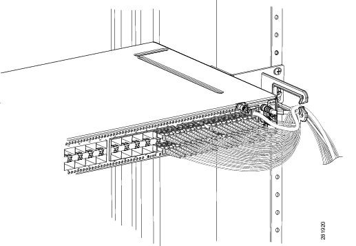 The cables are routed through the cable guide in an ETSI rack configuration, as shown in this figure. 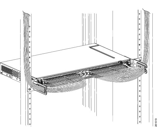
|
NTP-J60 Clean Fiber Connectors
| Purpose | This procedure explains how to clean the fiber connectors. |
| Tools/Equipment | |
| Prerequisite Procedures | None |
| Required/As Needed | Required |
| Onsite/Remote | Onsite |
| Security Level | None |
| Step 1 | Using an inspection microscope, inspect each fiber connector for dirt, cracks, or scratches. | ||
| Step 2 | Replace any damaged fiber connectors.
| ||
| Step 3 | Complete the DLP-J186 Clean Fiber Connectors with CLETOP as necessary. | ||
| Step 4 | Complete the DLP-J187 Clean the Fiber Adapters as necessary. | ||
| Step 5 | Stop. You have completed this procedure. |
DLP-J186 Clean Fiber Connectors with CLETOP
| Purpose | This task explains how to clean the fiber connectors with CLETOP. |
| Tools/Equipment | |
| Prerequisite Procedures | None |
| Required/As Needed | Required |
| Onsite/Remote | Onsite |
| Security Level | None |
| Step 1 | Remove the dust cap from the fiber connector. |
| Step 2 | Press the lever up to open the shutter door. Each time you press the lever, you expose a clean wiping surface. |
| Step 3 | Insert the connector into the CLETOP cleaning cassette slot, rotate one quarter turn, and gently swipe downwards. |
| Step 4 | Use an inspection microscope to inspect each fiber connector for dirt, cracks, or scratches. If the connector is not clean, repeat Step 1 to Step 3. |
| Step 5 | Insert the fiber connector into the applicable adapter or attach a dust cap to the fiber connector. |
| Step 6 | Return to your originating procedure (NTP). |
DLP-J187 Clean the Fiber Adapters
| Purpose | This task explains how to clean the fiber adapters. |
| Tools/Equipment | CLETOP stick swab |
| Prerequisite Procedures | None |
| Required/As Needed | Required |
| Onsite/Remote | Onsite |
| Security Level | None |
NTP-J61 Perform the CPT 50 Shelf Installation Acceptance Test
| Purpose | This procedure describes how to perform a shelf installation acceptance test for the CPT 50 shelf. |
| Tools/Equipment | Voltmeter |
| Prerequisite Procedures | Applicable procedures in this chapter |
| Required/As Needed | Required |
| Onsite/Remote | Onsite |
| Security Level | None |
| Step 1 | If you installed a CPT 50 shelf, verify that each applicable procedure listed in the below table was completed.
| ||||||||||||||
| Step 2 | DLP-J188 Inspect the CPT 50 Shelf Installation and Connections. | ||||||||||||||
| Step 3 | DLP-J189 Measure DC Voltage on the CPT 50 shelf. | ||||||||||||||
| Step 4 | Continue with NTP-J21 Set Up the Computer for CTC and NTP-J22 Log into CTC. Stop. You have completed this procedure. |
DLP-J188 Inspect the CPT 50 Shelf Installation and Connections
| Purpose | This task describes how to inspect the shelf installation and connections and verify that everything is installed and connected properly. |
| Tools/Equipment | None |
| Prerequisite Procedures | None |
| Required/As Needed | Required |
| Onsite/Remote | Onsite |
| Security Level | None |
DLP-J189 Measure DC Voltage on the CPT 50 shelf
| Purpose | This task describes how to measure the power to verify correct power and returns. |
| Tools/Equipment | Voltmeter |
| Prerequisite Procedures | Before installing the DC power, check the voltage |
| Required/As Needed | Required |
| Onsite/Remote | Onsite |
| Security Level | None |
Warning | To reduce the risk of electric shock, switch on the power only after the power cord is completely installed into the power module. Statement 390 |
Caution | Do not apply power to the shelf assembly until you complete all the installation steps. |
| Step 1 | Using a voltmeter, verify the office ground and power: |
| Step 2 | Using a voltmeter, verify the shelf ground and power wiring: Place the black lead (positive) on the RET1(A) and the red lead on the -48 V (A) or -24 V (A) point.
|
| Step 3 | Repeat Step 1 and Step 2 for the RET2 (B) and -48 V (B) or -24 V (B) of the redundant power supply input. |
| Step 4 | Return to your originating procedure (NTP). |
Hardware Specifications
This chapter contains product names and hardware specifications for CPT 50 shelf, fabric card, and line card.
Product Names
The product names for the CPT 50 shelf, fabric, and line cards are listed in this table.
| Card / Shelf | Product Name |
|---|---|
| Fabric Card | CPT-PTF256-10GX4= |
| Line Card | CPT-PTM-10GX4= |
| CPT 50 Shelf with 48 V AC power module | CPT-50-44GE-AC= |
| CPT 50 Shelf with 48 V DC power module for ANSI standard | CPT-50-44GE-48A |
| CPT 50 Shelf with 48 V DC power module for ETSI standard | CPT-50-44GE-48E= |
| CPT 50 Shelf with 24 DC power module for ANSI standard | CPT-50-44GE-24A= |
Caution | In order to ensure system reliability, the CPT 600 or CPT 200 shelf must have all their slots equipped with either cards or fillers. |
Note | The fabric and line cards are inserted in a CPT 600 or CPT 200 shelf. The line card filler (15454-M-FILLER) must be installed in unused and empty slots to ensure proper air flow and electromagnetic interference (EMI) requirements during the CPT 200 or CPT 600 operation. In the CPT 200 shelf, the line card filler can be installed in Slot 2 and Slot 3. In the CPT 600 shelf, the line card filler can be installed in slots 2, 3, 4, 5, 6, and 7. The line card fillers have no card-level LED indicators. CTC does not detect filler cards. This support may be added in later releases. |
CPT Specifications
This section provides the specifications for timing, power, and environmental specifications, card and shelf dimensions.
GPS (Global Positioning System) Interface (1PPS and 10Mhz) of CPT 50 Shelf
| 10 MHz Specification | 1 PPS Specification | |
|---|---|---|
| Waveform | Sine wave | Pulse |
| Frequency | 10 MHz | 1 PPS |
| Amplitude | >1 V LVTTL Compatible | >1 V LVTTL Compatible |
| Impedance | 50 Ω | 50 Ω |
TOD/1PPS RS422 Interface— RJ45 Pinout of CPT 50
The pinout of the TOD (Time of Day) RJ45 port is listed in this table.
| Pin | Signal Name | Description |
|---|---|---|
| 1 | 1PPS_N | 1PPS RS422 output signal |
| 2 | 1PPS_P | 1PPS RS422 output signal |
| 3 | NC | No Connect |
| 4 | GND | — |
| 5 | GND | — |
| 6 | NC | No Connect |
| 7 | TOD_P | Time of Day RS422 output |
| 8 | TOD_N | Time of Day RS422 output |
System Power for CPT 50 Shelf
The power specifications for the CPT 50 shelf is listed in this table.
Fan Tray
| Shelf | Input Voltage | Power Consumption | Power Terminals | Fuse Rating |
|---|---|---|---|---|
| CPT 50 shelf with AC power module for ANSI and ETSI standards | 100V - 240V AC depending on the standards in various countries | 100 VAC 2.4 A ; 240 VAC 1A | One AC single phase with 3- pole ( line L, Neutral N, and Protective Earth PE) input connector. | Must not exceed 10 A or 15 A, depending on the standards in various countries. |
| CPT 50 shelf with 48 V DC power module for ANSI standard | Voltages –40.5 VDC and –57.6 VDC are, respectively, the minimum and maximum voltages required to power the chassis. The nominal steady state voltage is -48 VDC. Functionality is guaranteed at -40 VDC input voltage, according to GR-1089. | 48 V DC 5 A | Single terminal block with four poles— –48V, RET for power terminals A and B. | Must not exceed 10 A |
| CPT 50 shelf with 48 V DC power module for ETSI standard | Voltages –40.5 VDC and –57.6 VDC are, respectively, the minimum and maximum voltages required to power the chassis. The nominal steady state voltage is -48 VDC. | 48 VDC 5 A | DSUB 2 poles | Must not exceed 10 A |
| CPT 50 shelf with 24 V DC power module for ANSI standard | Voltages –20 VDC and –28.3 VDC are, respectively, the minimum and maximum voltages required to power the chassis. The nominal steady state voltage is -24 VDC. | 24VDC 10 A | Single terminal block with four poles— –24V, RET for power terminals A and B. | Must not exceed 15 A. |
| Fan Tray | Watts | Amps |
|---|---|---|
| 12 V supplied by CPT 50 shelf | 36 | 3 |
Fabric Card and Line Card Power Specifications
This section provides power specifications for fabric and line cards.
| Card | Maximum Power in Watts | Typical Power in Watts | Amperes at -48 V (Maximum) |
|---|---|---|---|
| Fabric Card | 200 | 150 | 4.1 |
| Line Card | 150 | 100 | 2.1 |
CPT 50 Shelf, Fabric, and Line Card Dimensions
| Card / Shelf | Physical Dimensions | |||||||
|---|---|---|---|---|---|---|---|---|
| Measurement in inches | Measurement in mm | |||||||
| Height | Width | Depth | Weight in Kg | Height | Width | Depth | Weight in Kg | |
| Fabric and Line Card (Single Slot) | 12.650 | 0.921 | 9.000 | 321.3 | 23.4 | 228.6 |
|
|
| CPT 50 Shelf | 1.7 |
|
9.1 |
|
43.1 |
|
231.1 | |
The operating temperature and humidity for CPT 50 shelf, fabric, and line cards are as follows:
| Card / Shelf | Interface | Switching Capacity |
|---|---|---|
| Fabric Card |
|
256 G |
| Line Card |
|
40 G |
| CPT 50 Shelf |
44 G |
SFP, SFP+, and XFP Modules
SFP, SFP+, and 10-Gbps SFP (XFP) modules are integrated fiber optic transceivers that provide high-speed serial links from a port or slot to the network. For more information on SFP/SFP+/XFP modules and for a list of SFP/SFP+/XFP modules supported by the CPT, see Installing the SFP, SFP+, and XFP Modules in Cisco CPT. In CTC, SFP, SFP+, and XFP modules are called pluggable port modules (PPMs).
 Feedback