System Setup and Software Installation Guide for Cisco Optical Site Manager, IOS XR
Bias-Free Language
The documentation set for this product strives to use bias-free language. For the purposes of this documentation set, bias-free is defined as language that does not imply discrimination based on age, disability, gender, racial identity, ethnic identity, sexual orientation, socioeconomic status, and intersectionality. Exceptions may be present in the documentation due to language that is hardcoded in the user interfaces of the product software, language used based on RFP documentation, or language that is used by a referenced third-party product. Learn more about how Cisco is using Inclusive Language.
Cable and configure the related network interfaces (physical or virtual).
Both the configuration files are identical and contain the data for both the
servers in HA. The only difference is the server-name attribute that
contains the name of the server to which the file is applied.
Network YAML configuration file
The network YAML configuration file includes essential network details needed to set up the SVO-LC interfaces and the Cisco
Optical Site Manager application network infrastructure.
The redundancy-mode must be set to "GEO_HA" for initiating Geo high availability.
Each SVO-LC has an individual network YAML file for installation. When deploying two SVO-LCs for high availability, the only
difference between the two files should be the value of the server-name field.
Here an example of IPv4 Network YAML configuration file for Geo HA configuration.
This table describes the fields in the network.yml configuration files.
Table 2.
Field
Description
server-name
The name of the SVO-LC being installed. It name must be same as one of the server.name entries.
mgmt-address-family
Indicates the address family for the management network. Acceptable values include:
IPv4
In all three scenarios, the mgmt:ipv4 section must be included.
ospf-area-id
The OSPF area ID associated with the NCS 2000 device.
redundancy-mode
This is an optional field, necessary only when using Geo HA mode; otherwise, it can be omitted.
The valid value is: GEO_HA
servers
A list of SVO-LCs along with their network details.
servers.name
The name of the SVO-LC.
mgmt
Details about the management network.
Subsection is ipv4 for the mgmt-address-family value.
ip: Specify the subnet.
prefix: Specify the subnet mask.
gateway: Specify the gateway for the subnet.
host-nic: Represents the IP address assigned to the SVO-LC br-management interface, which is also used by the Cisco Optical Site Manager
Administration Plane web UI via HTTPS on port 443.
devices
The network details for NCS 2000 devices.
ip: Specify the subnet.
prefix: Specify the subnet mask.
gateway: Specify the gateway for the subnet.
host-nic: Represents the IP address assigned to the SVO-LC br-management interface, which is also used by the Cisco Optical Site Manager
Administration Plane web UI via HTTPS on port 443.
Install Cisco Optical Site Manager
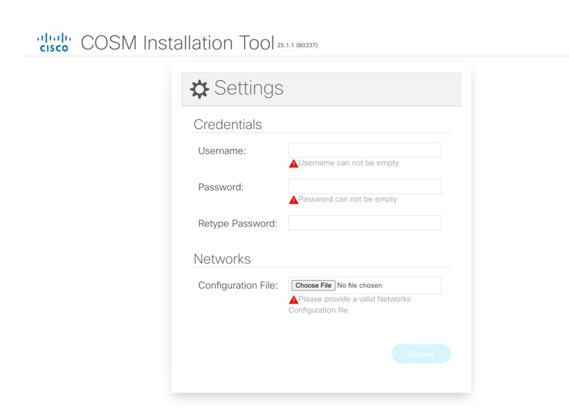
You can install Cisco Optical Site Manager using the COSM Installation Tool, a web-based application designed to install Cisco Optical Site Manager on NCS 2000 SVO-LC. To set up the Geo HA environment,
the tool requires a network YAML file. Additionally, it assists in creating the administrator user ID and password.
Follow these steps to install Cisco Optical Site Manager using the COSM Installation Tool.
The password must be a minimum of eight characters, and it can be a maximum of 127 characters. The password must have at least
one uppercase letter, one lowercase character, one number, and one special character.
Retype the password in the Retype Password field.
Figure 1. COSM Installation Tool Settings page
Step 3
Click Choose File to select the network.yml file from the Configuration File field.
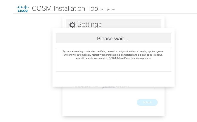
Click the Submit button to start the installation process.
A confirmation message is displayed, indicating that the credentials have been created, the network configuration file has
been verified, and the system has been brought up.
After the installation completes, a blank web page appears, indicating that the COSM Admin Plane has successfully started.
To define SVO instances, ensure the necessary resources are allocated. For high availability, allocate identical resources
on both VMs to maintain consistency and failover support.
Supported resources
Table 3. Supported resources per Node or Instance
Node or Instance
Memory
Degree
Maximum memory allowed
OLA / ROADM
2.1 GB
up to 4 degrees
32 GB
ROADM
4 GB
greater than 4 degrees
HA deployment modes
You can deploy HA in the different modes:
Local HA
Geo HA between adjacent nodes using UDC channel
Geo HA between nearby NCS 2000 nodes
Local HA (Local High Availability)
Local HA mode provides high availability by inserting two SVO-LCs into the same NCS 2000 node. This setup ensures redundancy
within a single node.
In Local HA mode, two SVO-LCs are installed within the same NCS 2000 node. It provides redundancy by using two SVO-LCs in
the same NCS 2000 node and ensures high availability by enabling failover to the standby SVO-LC in case of primary SVO-LC
failure. Simplifies deployment by keeping all components within a single node.
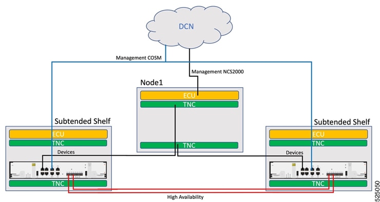
This image shows the Local HA connection for NCS 2000 multishelf node.
Figure 2. Local HA connection for NCS 2000 multishelf node
The connection requirements for each SVO-LC are outlined below:
Connect MGMT1 port to the customer Data Communication Network (DCN).
Connect two optical fibers, necessitating the insertion of two pluggables into the SVO-LC card's HA1 and HA2 ports.
Connect Port 1 to one TNC and peer SVO-LC port 1 connected to the other TNC.
(Optional) Connect NCS 2000 ECU EMS connected to customer DCN (in case of multishelf, the ECU of master chassis), in case
there is a specific requirement of direct accessibility of the NCS 2000 device.
Geographic high availability
In Geo HA mode, two SVO-LCs are installed in separate NCS 2000 nodes. The high availability network between these SVO-LCs
is transported through the User-Defined Channel (UDC) channel. Each SVO-LC runs a Cisco Optical Site Manager Admin Plane,
managing its local line card and communicating with its peer on the other SVO-LC. A Cisco Optical Site Manager instance, representing
a virtual network element (vNE), runs on both SVO-LCs, with one in Active state and the other in Standby state.
Benefits of geo HA
Geo HA offers several benefits in terms of redundancy and network reliability:
Utilizes two SVO-LCs located in separate NCS 2000 nodes to provide robust redundancy.
Utilizes the UDC channel or the SVO-LC optical pluggables to transmit high-availability data between adjacent nodes, ensuring
uninterrupted operations.
Facilitates failover to the standby SVO-LC in the event of primary SVO-LC failure, increasing network resilience.
Geo HA using the UDC channel
Geo HA Mode is a configuration that enhances network reliability and availability by placing two SVO-LC cards into two adjacent
NCS 2000 nodes. The UDC channel is utilized to transport the high availability network, ensuring continuous service even in
the event of failures.
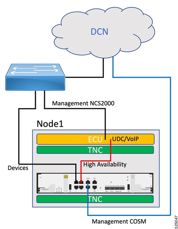
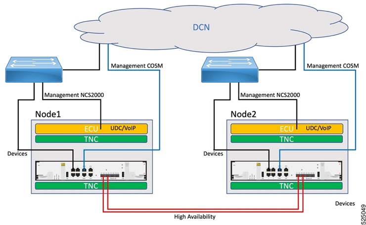
This image shows the Geo HA connection using the UDC channel.
Figure 3. Geo HA connection using the UDC channel
The Geo HA link is implemented using the available NCS 2000 UDC channel, enabling packet processing at the hardware level
without impacting the NCS 2000 controller CPU. It supports a single-path UDC HA link with a theoretical bandwidth of 80 Mbps.
It is important to note that connecting one of the optical HA ports to the local ECU UDC port using the electrical ONS-SE-ZE-EL-C
pluggable is not possible. This limitation arises from a re-timer connected to the PPM, which only supports a 1G rate, whereas
the NCS 2000 UDC port operates at an FE rate. To address this, port 3 is reconfigured as an electrical HA port and will properly
negotiate the FE speed.
The UDC must be configured through CTC, as the Cisco Optical Site Manager does not support this functionality. The UDC is
set on the Transponder Node Controller (TNC) pluggable associated with the Optical Supervisory Channel (OSC) connected to
the side facing the adjacent node. The same configuration is applied to the corresponding TNC pluggable on the adjacent NCS
2000 node.
Each SVO-LC must be connected as below:
Connect MGMT1 port to the customer Data Communication Network (DCN).
Connect port 3 to the NCS 2000 ECU UDC/VoIP.
Connect port 1 to the NCS 2000 ECU EMS or the same switch (same VLAN) where NCS 2000 ECU EMS is connected.
(Optional) NCS 2000 ECU EMS may connect directly to the customer DCN for multishelf setups, offering direct accessibility
to the NCS2000 device if needed.
Geo HA between nearby NCS 2000 nodes
In Geo HA mode involving nearby NCS 2000 nodes, the two SVO-LCs are installed in separate NCS 2000 nodes, likely situated
within the same building or close enough to allow direct interconnection of the two SVO-LCs through HA optical pluggables.
This image shows Geo HA between nearby NCS 2000 nodes.
 Feedback