- Preface
- Cisco ONS Documentation Roadmap for Release 9.6.x
- New and Changed Information
- Chapter 1, Install the Cisco ONS 15454, ONS 15454 M2, and ONS 15454 M6 Shelf
- Chapter 2, Connecting the PC and Logging into the GUI
- Chapter 3, Install the Control Cards
- Chapter 4, Setup Optical Service Channel Cards
- Chapter 5, Optical Amplifier Cards
- Chapter 6, Provision Multiplexer and Demultiplexer Cards
- Chapter 7, Setup Tunable Dispersion Compensating Units
- Chapter 8, Provision Protection Switching Module
- Chapter 9, Optical Add/Drop Cards
- Chapter 10, Reconfigurable Optical Add/Drop Cards
- Chapter 11, Provision Transponder and Muxponder Cards
- Chapter 12, Node Reference
- Chapter 13, Network Reference
- Chapter 14, Turn Up a Node
- Chapter 15, Perform Node Acceptance Tests
- Chapter 16, Turn Up a Network
- Chapter 17, Create Optical Channel Circuits and Provisionable Patchcords
- Chapter 18, Monitor Performance
- Chapter 19, Manage the Node
- Chapter 20, Alarm and TCA Monitoring and Management
- Chapter 21, Change DWDM Card Settings
- Chapter 22, Manage Network Connectivity
- Chapter 23, Upgrade, Add, and Remove Cards and Nodes
- Chapter 24, Maintain the Node
- Chapter 25, Security Reference
- Chapter 26, Timing Reference
- Chapter 27, SNMP
- Appendix A, CTC Operation, Information, and Shortcuts
- Appendix B, Hardware Specifications
- Appendix C, Administrative and Service States
- Appendix D, Configure GE_XP, 10GE_XP, GE_XPE, and 10GE_XPE Cards Using PCLI
- Appendix E, Pseudo Command Line Interface Reference
- Appendix F, Fiber and Connector Losses in Raman Link Configuration
- Appendix G, Card Features
- Appendix H, Network Element Defaults
Provision Multiplexer and Demultiplexer Cards
This chapter describes legacy multiplexer and demultiplexer cards used in Cisco ONS 15454 dense wavelength division multiplexing (DWDM) networks and related procedures.
For card safety and compliance information, see the Regulatory Compliance and Safety Information for Cisco CPT and Cisco ONS Platforms document.

Note![]() Unless otherwise specified, “ONS 15454” refers to both ANSI and ETSI shelf assemblies.
Unless otherwise specified, “ONS 15454” refers to both ANSI and ETSI shelf assemblies.
- Card Overview
- Safety Labels
- 32MUX-O Card
- Related Procedures for the 32MUX-O Card
- 32DMX-O Card
- Related Procedures for the 32DMX-O Card
- 4MD-xx.x Card
- Related Procedures for the 4MD-xx.x Card
Note![]() For a description of the 32DMX, 32DMX-L, 40-DMX-C, 40-DMX-CE, 40-MUX-C, 40-WSS-C, 40-WSS-CE, and 40-WXC-C cards, see the “Provision Reconfigurable Optical Add/Drop Cards” chapter.
For a description of the 32DMX, 32DMX-L, 40-DMX-C, 40-DMX-CE, 40-MUX-C, 40-WSS-C, 40-WSS-CE, and 40-WXC-C cards, see the “Provision Reconfigurable Optical Add/Drop Cards” chapter.
6.1 Card Overview
The card overview section contains card summary, compatibility, interface class, and channel allocation plan information for legacy multiplexer and demultiplexer cards.
Note![]() Each card is marked with a symbol that corresponds to a slot (or slots) on the ONS 15454 shelf assembly. The cards are then installed into slots displaying the same symbols. For a list of slots and symbols, see the “Card Slot Requirements” section in the Cisco ONS 15454 Hardware Installation Guide.
Each card is marked with a symbol that corresponds to a slot (or slots) on the ONS 15454 shelf assembly. The cards are then installed into slots displaying the same symbols. For a list of slots and symbols, see the “Card Slot Requirements” section in the Cisco ONS 15454 Hardware Installation Guide.
6.1.1 Card Summary
Table 6-1 lists and summarizes the functions of the 32MUX-O, 32DMX-O, and 4MD-xx.x cards.
|
|
|
|
|---|---|---|
|
|
The 32MUX-O has five sets of ports located on the faceplate. It operates in Slots 1 to 5 and 12 to 16. |
See the “32MUX-O Card” section. |
|
|
The 32DMX-O has five sets of ports located on the faceplate. It operates in Slots 1 to 5 and 12 to 16. |
|
|
|
The 4MD-xx.x card has five sets of ports located on the faceplate. It operates in Slots 1 to 6 and 12 to 17. |
See the “4MD-xx.x Card” section. |
6.1.2 Card Compatibility
Table 6-2 lists the CTC software compatibility for the legacy cards.
|
|
|
||
|---|---|---|---|
|
|
|
|
|
6.1.3 Interface Classes
The 32MUX-O, 32DMX-O, and 4MD-xx.x cards have different input and output optical channel signals depending on the interface card where the input signal originates. The input interface cards have been grouped in classes listed in Table 6-3 . The subsequent tables list the optical performance and output power of each interface class.
Table 6-5 lists the optical performance parameters for 40-Gbps cards that provide signal input to multiplexer and demultiplexer cards.
|
|
|
|
|
|||
|---|---|---|---|---|---|---|
|
|
|
|
|
|
|
|
Maximum BER2 |
||||||
OSNR 1 sensitivity |
||||||
| Transmitted Power Range3 |
||||||
40-Gbps multirate transponder/40-Gbps EC transponder (40E-TXP-C and 40ME-TXP-C) |
||||||
|
3.These values, decreased by patchcord and connector losses, are also the input power values for the OADM cards. |
Table 6-5 lists the optical performance parameters that provide signal input for the 40-Gbps multiplexer and demultiplexer cards.
|
|
|
|
|
|
|||
|---|---|---|---|---|---|---|---|
|
|
|
|
|
|
|
|
|
Maximum BER5 |
|||||||
OSNR 1 sensitivity |
|||||||
| Transmitted Power Range6 |
|||||||
10-Gbps multirate transponder/10-Gbps FEC transponder (TXP_MR_10G) |
|||||||
10-Gbps multirate transponder/10-Gbps FEC transponder (TXP_MR_10E) |
|||||||
|
6.These values, decreased by patchcord and connector losses, are also the input power values for the OADM cards. |
Table 6-6 lists the optical interface performance parameters for 2.5-Gbps cards that provide signal input to multiplexer and demultiplexer cards.
|
|
|
|
|
|
|
|
||||
|---|---|---|---|---|---|---|---|---|---|---|
|
|
|
|
|
|
|
|
|
|
|
|
| Transmitted Power Range7 |
||||||||||
|
7.These values, decreased by patchcord and connector losses, are also the input power values for the OADM cards. |
6.1.4 Channel Allocation Plan
ONS 15454 DWDM multiplexer and demultiplexer cards are designed for use with specific channels in the C band and L band. In most cases, the channels for these cards are either numbered (for example, 1 to 32 or 1 to 40) or delimited (odd or even). Client interfaces must comply with these channel assignments to be compatible with the ONS 15454 system.
Table 6-7 lists the channel IDs and wavelengths assigned to the C-band DWDM channels.
Note![]() In some cases, a card uses only one of the bands (C band or L band) and some or all of the channels listed in a band. Also, some cards use channels on the 100-GHz ITU grid while others use channels on the 50-GHz ITU grid. See the specific card description or the “Hardware Specifications” document for more details.
In some cases, a card uses only one of the bands (C band or L band) and some or all of the channels listed in a band. Also, some cards use channels on the 100-GHz ITU grid while others use channels on the 50-GHz ITU grid. See the specific card description or the “Hardware Specifications” document for more details.
|
|
|
|
|
|
|
|---|---|---|---|---|---|
Table 6-8 lists the channel IDs and wavelengths assigned to the L-band channels.
|
|
|
|
|
|
|
|---|---|---|---|---|---|
6.2 Safety Labels
For information about safety labels, see the “Safety Labels” section”.
6.3 32MUX-O Card
Note![]() For 32MUX-O card specifications, see the “32MUX-O Card Specifications” section in the Hardware Specifications document.
For 32MUX-O card specifications, see the “32MUX-O Card Specifications” section in the Hardware Specifications document.
The 32-Channel Multiplexer (32MUX-O) card multiplexes 32 100-GHz-spaced channels identified in the channel plan. The 32MUX-O card takes up two slots in an ONS 15454 and can be installed in Slots 1 to 5 and 12 to 16.
6.3.1 32MUX-O Card Functions
The 32MUX-O functions include:
- Arrayed waveguide grating (AWG) device that enables full multiplexing functions for the channels.
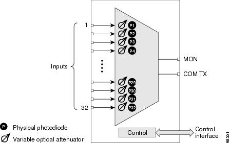
- Each single-channel port is equipped with VOAs for automatic optical power regulation prior to multiplexing. In the case of electrical power failure, the VOA is set to its maximum attenuation for safety purposes. A manual VOA setting is also available.
- Each single-channel port is monitored using a photodiode to enable automatic power regulation.
- Card level indicators—Table G-4
An additional optical monitoring port with 1:99 splitting ratio is available.
6.3.2 32MUX-O Card Faceplate and Block Diagram
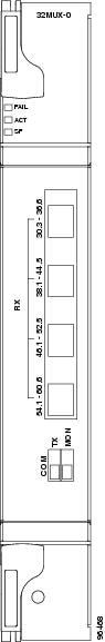
Figure 6-1 shows the 32MUX-O faceplate.
For information on safety labels for the card, see the “Safety Labels” section”.
Figure 6-2 shows a block diagram of the 32MUX-O card.
Figure 6-2 32MUX-O Block Diagram
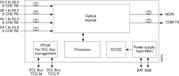
The 32MUX-O card has four receive connectors that accept multifiber push-on (MPO) cables on its front panel for the client input interfaces. MPO cables break out into eight separate cables. The 32MUX-O card also has two LC-PC-II optical connectors, one for the main output and the other for the monitor port.
Figure 6-3 shows the 32MUX-O optical module functional block diagram.
Figure 6-3 32MUX-O Optical Module Functional Block Diagram
6.3.2.1 Port-Level Indicators for the 32MUX-O Cards
The 32MUX-O card has five sets of ports located on the faceplate. COM TX is the line output. COM MON is the optical monitoring port. The xx.x to yy.y RX ports represent the four groups of eight channels ranging from wavelength xx.x to wavelength yy.y, according to the channel plan.
6.3.3 Channel Plan
The 32MUX-O is typically used in hub nodes and provides the multiplexing of 32 channels, spaced at 100 GHz, into one fiber before their amplification and transmission along the line. The channel plan is shown in Table 6-9 .
|
|
|
|
|
|---|---|---|---|
|
8.The Channel Number column is only for reference purposes. The channel ID is consistent with the ONS 15454 and is used in card identification. |
6.3.4 Power Monitoring
Physical photodiodes P1 through P32 monitor the power for the 32MUX-O card. The returned power level values are calibrated to the ports as shown in Table 6-10 .
|
|
|
|
|---|---|---|
For information on the associated TL1 AIDs for the optical power monitoring points, refer the “CTC Port Numbers and TL1 Aids” section in Cisco ONS SONET TL1 Command Guide.
6.3.5 Related Procedures for the 32MUX-O Card
The following is the list of procedures and tasks related to the configuration of the 32MUX-O card:
- G353 Preprovision a Slot
- G30 Install the DWDM Cards
- G143 Import the Cisco Transport Planner NE Update Configuration File
- G34 Install Fiber-Optic Cables on DWDM Cards and DCUs
- G140 Install Fiber-Optic Cables Between Terminal, Hub, or ROADM Nodes
- G315 Install Fiber-Optic Cables From the 32WSS/32DMX and 32MUX-O/32DMX-O Cards to the Standard Patch Panel Tray
- G356 Install Fiber-Optic Cables from the 32WSS/32DMX and 32MUX-O/32DMX-O Cards to the Deep Patch Panel Tray
- G184 Create a Provisionable Patchcord
- G152 Create and Verify Internal Patchcords
- G242 Create an Internal Patchcord Manually
- “ NTP-G86 Convert a Pass-Through Connection to Add/Drop Connections ”
- G41 Perform the Terminal or Hub Node with 32MUX-O and 32DMX-O Cards Acceptance Test
- G44 Perform the Anti-ASE Hub Node Acceptance Test
- “ NTP-G74 Monitor DWDM Card Performance ”
- “ DLP-G141 View Optical Power Statistics for 32MUX-O, 32WSS, 32WSS-L, 32DMX-O, 32DMX, 32DMX-L, 40-WSS-C, 40-WSS-CE, 40-WXC-C, 80-WXC-C, 40-MUX-C, 40-DMX-C, and 40-DMX-CE Cards ”
- G175 Modify 32MUX-O, 32DMX-O, 32DMX, 32DMX-L, 40-MUX-C, 40-DMX-C, 40-DMX-CE, and 4MD-xx.x Line Card Settings and PM Thresholds
- G414 Change Optical Line Settings for 32MUX-O, 32DMX-O, 32DMX, 32DMX-L, 40-MUX-C, 40-DMX-C, 40-DMX-CE, or 4MD-xx.x Cards
- G415 Change Optical Line Threshold Settings for 32MUX-O, 32DMX-O, 32DMX, 32DMX-L, 40-MUX-C, 40-DMX-C, 40-DMX-CE, or 4MD-xx.x Cards
- G416 Change Optical Channel Settings for 32MUX-O, 32DMX-O, 32DMX, 32DMX-L, 40-MUX-C, 40-DMX-C, 40-DMX-CE, or 4MD-xx.x Cards
- G417 Change Optical Channel Threshold Settings for 32MUX-O, 32DMX-O, 32DMX, 32DMX-L, 40-MUX-C, 40-DMX-C, 40-DMX-CE, or 4MD-xx.x Cards
- G78 Verify the 32MUX-O or 40-MUX-C Card Power
- G269 Verify the 32DMX-O or 40-DMX-C Card Power
- G355 Delete an Internal Patchcord
- G106 Reset Cards Using CTC
- G251 Reset DWDM Cards Using CTC
- “ NTP-G107 Remove Permanently or Remove and Replace DWDM Card ”
- G351 Delete a Card in CTC
- G119 Power Down the Node
6.4 32DMX-O Card
Note![]() For 32DMX-O card specifications, see the “32DMX-O Card Specifications” section in the Hardware Specifications document.
For 32DMX-O card specifications, see the “32DMX-O Card Specifications” section in the Hardware Specifications document.
The 32-Channel Demultiplexer (32DMX-O) card demultiplexes 32 100-GHz-spaced channels identified in the channel plan. The 32DMX-O takes up two slots in an ONS 15454 and can be installed in Slots 1 to 5 and 12 to 16.
6.4.1 32DMX-O Card Functions
The 32DMX-O functions include:
- AWG that enables channel demultiplexing functions.
- Each single-channel port is equipped with VOAs for automatic optical power regulation after demultiplexing. In the case of electrical power failure, the VOA is set to its maximum attenuation for safety purposes. A manual VOA setting is also available.
- The 32DXM-O has four physical receive connectors that accept MPO cables on its front panel for the client input interfaces. MPO cables break out into eight separate cables.
Note![]() In contrast, the single-slot 32DMX card does not have VOAs on each drop port for optical power regulation. The 32DMX optical demultiplexer module is used in conjunction with the 32WSS card in ONS 15454 Multiservice Transport Platform (MSTP) nodes.
In contrast, the single-slot 32DMX card does not have VOAs on each drop port for optical power regulation. The 32DMX optical demultiplexer module is used in conjunction with the 32WSS card in ONS 15454 Multiservice Transport Platform (MSTP) nodes.
- Each single-channel port is monitored using a photodiode to enable automatic power regulation.
- Card level indicators—Table G-4
6.4.2 32DMX-O Card Faceplate and Block Diagram
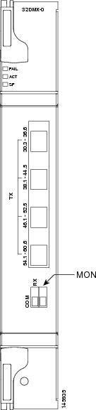
Figure 6-4 shows the 32DMX-O card faceplate.
For information on safety labels for the card, see the “Safety Labels” section”.
Figure 6-5 shows a block diagram of the 32DMX-O card.
Figure 6-5 32DMX-O Block Diagram
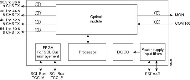
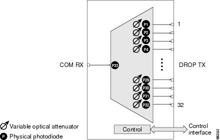
Figure 6-6 shows the 32DMX-O optical module functional block diagram.
Figure 6-6 32DMX-O Optical Module Functional Block Diagram
6.4.2.1 Port-Level Indicators for the 32DMX-O Cards
The 32DMX-O card has five sets of ports located on the faceplate. MON is the output monitor port. COM RX is the line input. The xx.x to yy.y TX ports represent the four groups of eight channels ranging from wavelength xx.x to wavelength yy.y according to the channel plan.
6.4.3 Power Monitoring
Physical photodiodes P1 through P33 monitor the power for the 32DMX-O card. The returned power level values are calibrated to the ports as shown in Table 6-11 .
|
|
|
|
|---|---|---|
For information on the associated TL1 AIDs for the optical power monitoring points, refer the “CTC Port Numbers and TL1 Aids” section in Cisco ONS SONET TL1 Command Guide, Release 9.2.1.
6.4.4 Related Procedures for the 32DMX-O Card
The following is the list of procedures and tasks related to the configuration of the 32DMX-O card:
- G353 Preprovision a Slot
- G30 Install the DWDM Cards
- G143 Import the Cisco Transport Planner NE Update Configuration File
- G34 Install Fiber-Optic Cables on DWDM Cards and DCUs
- G140 Install Fiber-Optic Cables Between Terminal, Hub, or ROADM Nodes
- G315 Install Fiber-Optic Cables From the 32WSS/32DMX and 32MUX-O/32DMX-O Cards to the Standard Patch Panel Tray
- G356 Install Fiber-Optic Cables from the 32WSS/32DMX and 32MUX-O/32DMX-O Cards to the Deep Patch Panel Tray
- G184 Create a Provisionable Patchcord
- G152 Create and Verify Internal Patchcords
- G242 Create an Internal Patchcord Manually
- “ NTP-G86 Convert a Pass-Through Connection to Add/Drop Connections ”
- G44 Perform the Anti-ASE Hub Node Acceptance Test
- G41 Perform the Terminal or Hub Node with 32MUX-O and 32DMX-O Cards Acceptance Test
- “ NTP-G74 Monitor DWDM Card Performance ”
- G78 Verify the 32MUX-O or 40-MUX-C Card Power
- G269 Verify the 32DMX-O or 40-DMX-C Card Power
- “ DLP-G141 View Optical Power Statistics for 32MUX-O, 32WSS, 32WSS-L, 32DMX-O, 32DMX, 32DMX-L, 40-WSS-C, 40-WSS-CE, 40-WXC-C, 80-WXC-C, 40-MUX-C, 40-DMX-C, and 40-DMX-CE Cards ”
- G175 Modify 32MUX-O, 32DMX-O, 32DMX, 32DMX-L, 40-MUX-C, 40-DMX-C, 40-DMX-CE, and 4MD-xx.x Line Card Settings and PM Thresholds
- G414 Change Optical Line Settings for 32MUX-O, 32DMX-O, 32DMX, 32DMX-L, 40-MUX-C, 40-DMX-C, 40-DMX-CE, or 4MD-xx.x Cards
- G415 Change Optical Line Threshold Settings for 32MUX-O, 32DMX-O, 32DMX, 32DMX-L, 40-MUX-C, 40-DMX-C, 40-DMX-CE, or 4MD-xx.x Cards
- G416 Change Optical Channel Settings for 32MUX-O, 32DMX-O, 32DMX, 32DMX-L, 40-MUX-C, 40-DMX-C, 40-DMX-CE, or 4MD-xx.x Cards
- G417 Change Optical Channel Threshold Settings for 32MUX-O, 32DMX-O, 32DMX, 32DMX-L, 40-MUX-C, 40-DMX-C, 40-DMX-CE, or 4MD-xx.x Cards
- G355 Delete an Internal Patchcord
- G106 Reset Cards Using CTC
- G251 Reset DWDM Cards Using CTC
- “ NTP-G107 Remove Permanently or Remove and Replace DWDM Card ”
- G351 Delete a Card in CTC
- G119 Power Down the Node
6.5 4MD-xx.x Card
Note![]() For 4MD-xx.x card specifications, see the section “4MD-xx.x Card Specifications” section in the Hardware Specifications document.
For 4MD-xx.x card specifications, see the section “4MD-xx.x Card Specifications” section in the Hardware Specifications document.
The 4-Channel Multiplexer/Demultiplexer (4MD-xx.x) card multiplexes and demultiplexes four 100-GHz-spaced channels identified in the channel plan. The 4MD-xx.x card is designed to be used with band OADMs (both AD-1B-xx.x and AD-4B-xx.x).
The card is bidirectional. The demultiplexer and multiplexer functions are implemented in two different sections of the same card. In this way, the same card can manage signals flowing in opposite directions.
There are eight versions of this card that correspond with the eight sub-bands specified in Table 6-12. The 4MD-xx.x can be installed in Slots 1 to 6 and 12 to 17.
6.5.1 4MD-xx.x Card Functions
The 4MD-xx.x has the following functions implemented inside a plug-in optical module:
- Passive cascade of interferential filters perform the channel multiplex/demultiplex function.
- Software-controlled VOAs at every port of the multiplex section regulate the optical power of each multiplexed channel.
- Software-monitored photodiodes at the input and output multiplexer and demultiplexer ports for power control and safety purposes.
- Software-monitored virtual photodiodes at the common DWDM output and input ports. A virtual photodiode is a firmware calculation of the optical power at that port. This calculation is based on the single channel photodiode reading and insertion losses of the appropriated paths.
- Card level indicators—Table G-4
6.5.2 4MD-xx.x Card Faceplate and Block Diagram
Figure 6-7 shows the 4MD-xx.x faceplate.

For information on safety labels for the card, see the “Safety Labels” section”.
Figure 6-8 shows a block diagram of the 4MD-xx.x card.
Figure 6-8 4MD-xx.x Block Diagram
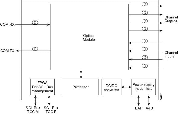
Figure 6-9 shows the 4MD-xx.x optical module functional block diagram.
Figure 6-9 4MD-xx.x Optical Module Functional Block Diagram
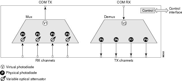
The optical module shown in Figure 6-9 is optically passive and consists of a cascade of interferential filters that perform the channel multiplexing and demultiplexing functions.
VOAs are present in every input path of the multiplex section in order to regulate the optical power of each multiplexed channel. Some optical input and output ports are monitored by means of photodiodes implemented both for power control and for safety purposes. An internal control manages VOA settings and functionality as well as photodiode detection and alarm thresholds. The power at the main output and input ports is monitored through the use of virtual photodiodes. A virtual photodiode is implemented in the firmware of the plug-in module. This firmware calculates the power on a port, summing the measured values from all single channel ports (and applying the proper path insertion loss) and then providing the TCC2/TCC2P/TCC3/TNC/TNCE/TSC/TSCE card with the obtained value.
6.5.2.1 Port-Level Indicators for the 4MD-xx.x Cards
The 4MD-xx.x card has five sets of ports located on the faceplate. COM RX is the line input. COM TX is the line output. The 15xx.x TX ports represent demultiplexed channel outputs 1 to 4. The 15xx.x RX ports represent multiplexed channel inputs 1 to 4.
6.5.3 Wavelength Pairs
Table 6-12 shows the band IDs and the add/drop channel IDs for the 4MD-xx.x card.
|
|
|
|---|---|
6.5.4 Power Monitoring
Physical photodiodes P1 through P8 and virtual photodiodes V1 and V2 monitor the power for the 4MD-xx.x card. The returned power level values are calibrated to the ports as shown in Table 6-13 .
|
|
|
|
|---|---|---|
For information on the associated TL1 AIDs for the optical power monitoring points, refer the “CTC Port Numbers and TL1 Aids” section in Cisco ONS SONET TL1 Command Guide, Release 9.2.1.
6.5.5 Related Procedures for the 4MD-xx.x Card
The following is the list of procedures and tasks related to the configuration of the 4MD-xx.x card:
- G353 Preprovision a Slot
- G30 Install the DWDM Cards
- G143 Import the Cisco Transport Planner NE Update Configuration File
- G48 Perform the OADM Node Acceptance Test on a Symmetric Node with OSCM Cards
- G89 Verify OADM Node Pass-Through Channel Connections
- G92 Verify 4MD-xx.x Pass-Through Connection Power
- G93 Verify Add and Drop Connections on an OADM Node with OSCM Cards
- G49 Perform the Active OADM Node Acceptance Test on a Symmetric Node with OSC-CSM Cards
- G94 Verify Add and Drop Connections on an OADM Node with OSC-CSM Cards
- G59 Create, Delete, and Manage Optical Channel Network Connections
- G105 Provision Optical Channel Network Connections
- G34 Install Fiber-Optic Cables on DWDM Cards and DCUs
- G140 Install Fiber-Optic Cables Between Terminal, Hub, or ROADM Nodes
- G315 Install Fiber-Optic Cables From the 32WSS/32DMX and 32MUX-O/32DMX-O Cards to the Standard Patch Panel Tray
- G356 Install Fiber-Optic Cables from the 32WSS/32DMX and 32MUX-O/32DMX-O Cards to the Deep Patch Panel Tray
- G184 Create a Provisionable Patchcord
- G152 Create and Verify Internal Patchcords
- G242 Create an Internal Patchcord Manually
- G41 Perform the Terminal or Hub Node with 32MUX-O and 32DMX-O Cards Acceptance Test
- G44 Perform the Anti-ASE Hub Node Acceptance Test
- “ NTP-G86 Convert a Pass-Through Connection to Add/Drop Connections ”
- “ NTP-G74 Monitor DWDM Card Performance ”
- G78 Verify the 32MUX-O or 40-MUX-C Card Power
- G269 Verify the 32DMX-O or 40-DMX-C Card Power
- “ DLP-G141 View Optical Power Statistics for 32MUX-O, 32WSS, 32WSS-L, 32DMX-O, 32DMX, 32DMX-L, 40-WSS-C, 40-WSS-CE, 40-WXC-C, 80-WXC-C, 40-MUX-C, 40-DMX-C, and 40-DMX-CE Cards ”
- G175 Modify 32MUX-O, 32DMX-O, 32DMX, 32DMX-L, 40-MUX-C, 40-DMX-C, 40-DMX-CE, and 4MD-xx.x Line Card Settings and PM Thresholds
- G414 Change Optical Line Settings for 32MUX-O, 32DMX-O, 32DMX, 32DMX-L, 40-MUX-C, 40-DMX-C, 40-DMX-CE, or 4MD-xx.x Cards
- G415 Change Optical Line Threshold Settings for 32MUX-O, 32DMX-O, 32DMX, 32DMX-L, 40-MUX-C, 40-DMX-C, 40-DMX-CE, or 4MD-xx.x Cards
- G416 Change Optical Channel Settings for 32MUX-O, 32DMX-O, 32DMX, 32DMX-L, 40-MUX-C, 40-DMX-C, 40-DMX-CE, or 4MD-xx.x Cards
- G417 Change Optical Channel Threshold Settings for 32MUX-O, 32DMX-O, 32DMX, 32DMX-L, 40-MUX-C, 40-DMX-C, 40-DMX-CE, or 4MD-xx.x Cards
- G355 Delete an Internal Patchcord
- G106 Reset Cards Using CTC
- G251 Reset DWDM Cards Using CTC
- “ NTP-G107 Remove Permanently or Remove and Replace DWDM Card ”
- G351 Delete a Card in CTC
- G119 Power Down the Node
 Feedback