- Preface
- Cisco ONS Documentation Roadmap for Release 9.6.x
- New and Changed Information
- Chapter 1, Install the Cisco ONS 15454, ONS 15454 M2, and ONS 15454 M6 Shelf
- Chapter 2, Connecting the PC and Logging into the GUI
- Chapter 3, Install the Control Cards
- Chapter 4, Setup Optical Service Channel Cards
- Chapter 5, Optical Amplifier Cards
- Chapter 6, Provision Multiplexer and Demultiplexer Cards
- Chapter 7, Setup Tunable Dispersion Compensating Units
- Chapter 8, Provision Protection Switching Module
- Chapter 9, Optical Add/Drop Cards
- Chapter 10, Reconfigurable Optical Add/Drop Cards
- Chapter 11, Provision Transponder and Muxponder Cards
- Chapter 12, Node Reference
- Chapter 13, Network Reference
- Chapter 14, Turn Up a Node
- Chapter 15, Perform Node Acceptance Tests
- Chapter 16, Turn Up a Network
- Chapter 17, Create Optical Channel Circuits and Provisionable Patchcords
- Chapter 18, Monitor Performance
- Chapter 19, Manage the Node
- Chapter 20, Alarm and TCA Monitoring and Management
- Chapter 21, Change DWDM Card Settings
- Chapter 22, Manage Network Connectivity
- Chapter 23, Upgrade, Add, and Remove Cards and Nodes
- Chapter 24, Maintain the Node
- Chapter 25, Security Reference
- Chapter 26, Timing Reference
- Chapter 27, SNMP
- Appendix A, CTC Operation, Information, and Shortcuts
- Appendix B, Hardware Specifications
- Appendix C, Administrative and Service States
- Appendix D, Configure GE_XP, 10GE_XP, GE_XPE, and 10GE_XPE Cards Using PCLI
- Appendix E, Pseudo Command Line Interface Reference
- Appendix F, Fiber and Connector Losses in Raman Link Configuration
- Appendix G, Card Features
- Appendix H, Network Element Defaults
- G.1 Safety Labels
- G.1.1 Class 1 Laser Product Cards
- G.1.1.1 Class 1 Laser Product Label
- G.1.1.2 Hazard Level 1 Label
- G.1.1.3 Laser Source Connector Label
- G.1.1.4 FDA Statement Labels
- G.1.1.5 Shock Hazard Label
- G.1.2 Class 1M Laser Product Cards
- G.1.2.1 Class 1M Laser Product Statement
- G.1.2.2 Hazard Level 1M Label
- G.1.2.3 Laser Source Connector Label
- G.1.2.4 FDA Statement Labels
- G.1.2.5 Shock Hazard Label
- G.1.2.6 Burn Hazard Label
- G.2 Automatic Laser Shutdown
- G.3 Card-Level Indicators
- G.4 Port-Level Indicators
- G.5 Client Interface
- G.6 DWDM Interface
- G.7 DWDM Trunk Interface
- G.8 FEC
- G.9 Client-to-Trunk Mapping
- G.10 Timing Synchronization
- G.11 Multiplexing Function
- G.12 SONET/SDH Overhead Byte Processing
- G.13 Client Interface Monitoring
- G.14 Jitter
- G.15 Lamp Test
- G.16 Onboard Traffic Generation
- G.17 Performance Monitoring
- G.18 Distance Extension
- G.19 Slot Compatibility
- G.20 Interoperability with Cisco MDS Switches
- G.21 Client and Trunk Ports
- G.22 Communication and Control for Controller Cards
- G.23 Interface Ports
- G.24 External Alarms and Controls
- G.25 Digital Image Signing (DIS)
- G.26 Database Storage
- G.27 Redundant Controller Card Installation
- G.28 Optical Service Channel
- G.29 MultiShelf Management
- G.30 Protection Schemes
- G.31 Cards Supported by TNC/TNCE/TSC/TSCE
- G.32 Automatic Power Control
- G.33 Alarms and Thresholds
- G.34 Card Protection
- G.35 Far-End Laser Control
- G.36 Jitter Considerations
- G.37 Termination Modes
Card Features
This chapter describes features common to the Cisco ONS 15454 suite of cards.

Note![]() Unless otherwise specified, “ONS 15454” refers to both ANSI and ETSI shelf assemblies.
Unless otherwise specified, “ONS 15454” refers to both ANSI and ETSI shelf assemblies.
Note![]() The cards described in this chapter are supported on the Cisco ONS 15454, Cisco ONS 15454 M6, Cisco ONS 15454 M2 platforms, unless noted otherwise.
The cards described in this chapter are supported on the Cisco ONS 15454, Cisco ONS 15454 M6, Cisco ONS 15454 M2 platforms, unless noted otherwise.
Note![]() In this chapter, “RAMAN-CTP” refers to the 15454-M-RAMAN-CTP card. “RAMAN-COP” refers to the 15454-M-RAMAN-COP card.
In this chapter, “RAMAN-CTP” refers to the 15454-M-RAMAN-CTP card. “RAMAN-COP” refers to the 15454-M-RAMAN-COP card.
Note![]() In this chapter, “100G-LC-C card” refers to the 15454-M-100G-LC-C card. “10x10G-LC” refers to the 15454-M-10x10G-LC card. “CFP-LC” refers to the 15454-M-CFP-LC card.
In this chapter, “100G-LC-C card” refers to the 15454-M-100G-LC-C card. “10x10G-LC” refers to the 15454-M-10x10G-LC card. “CFP-LC” refers to the 15454-M-CFP-LC card.
G.1 Safety Labels
This section explains the significance of the safety labels attached to some cards. The faceplates of the cards are clearly labeled with warnings about the laser radiation levels. You must understand all warning labels before working on these cards.
G.1.1 Class 1 Laser Product Cards
The TCC2, TCC2P, TCC3, TNC, TNCE, TSC, TSCE, OSCM, OSC-CSM, 32MUX-O, 32DMX-O, 4MD-xx.x, MXP_2.5G_10G, MXP_2.5G_10E, MXP_2.5G_10E_C, MXP_2.5G_10E_L, ADM-10G, GE_XP, 10GE_XP, GE_XPE, 10GE_XPE, and OTU2_XP cards are Class 1 laser products.
The labels that appear on these cards are described in the following sections.
G.1.1.1 Class 1 Laser Product Label
The Class 1 Laser Product label is shown in Figure G-1.
Figure G-1 Class 1 Laser Product Label

Class 1 lasers are products whose irradiance does not exceed the Maximum Permissible Exposure (MPE) value. Therefore, for Class 1 laser products the output power is below the level at which it is believed eye damage will occur. Exposure to the beam of a Class 1 laser will not result in eye injury and can therefore be considered safe. However, some Class 1 laser products might contain laser systems of a higher Class but there are adequate engineering control measures to ensure that access to the beam is not reasonably likely. Anyone who dismantles a Class 1 laser product that contains a higher Class laser system is potentially at risk of exposure to a hazardous laser beam
G.1.1.2 Hazard Level 1 Label
The Hazard Level 1 label is shown in Figure G-2. This label is displayed on the faceplate of the cards.

The Hazard Level label warns users against exposure to laser radiation of Class 1 limits calculated in accordance with IEC60825-1 Ed.1.2.
G.1.1.3 Laser Source Connector Label
The Laser Source Connector label is shown in Figure G-3.
Figure G-3 Laser Source Connector Label

This label indicates that a laser source is present at the optical connector where the label has been placed.
G.1.1.4 FDA Statement Labels
The FDA Statement labels are shown in Figure G-4 and Figure G-5. These labels show compliance to FDA standards and that the hazard level classification is in accordance with IEC60825-1 Am.2 or Ed.1.2.
Figure G-4 FDA Statement Label
Figure G-5 FDA Statement Label
G.1.1.5 Shock Hazard Label
The Shock Hazard label is shown in Figure G-6.

This label alerts personnel to electrical hazard within the card. The potential of shock hazard exists when removing adjacent cards during maintenance, and touching exposed electrical circuitry on the card itself.
G.1.2 Class 1M Laser Product Cards
The OPT-PRE, OPT-BST, OPT-BST-E, OPT-BST-L, OPT-AMP-L, OPT-AMP-17-C, OPT-AMP-C, OPT-RAMP-C, OPT-RAMP-CE, OPT-EDFA-17, OPT-EDFA-24, RAMAN-CTP, RAMAN-COP, TDC-CC, TDC-FC, PSM, AD-1C-xx.x, AD-2C-xx.x, AD-4c-xx.x, AD-1B-xx.x, AD-4B-xx.x, 32WSS, 32WSS-L, 32DMX, 32DMX-L, 40-DMX-C, 40-DMX-CE, 40-MUX-C, 40-WSS-C, 40-WSS-CE, 40-WXC-C, 80-WXC-C, 40-SMR1-C, 40-SMR2-C, MMU, TXP_MR_10G, TXP_MR_10E, TXP_MR_10E_C, TXP_MR_10E_L, TXP_MR_2.5G, TXPP_MR_2.5G, MXP_MR_2.5G, MXPP_MR_2.5G, MXP_MR_10DME_C, MXP_MR_10DME_L, 40E-TXP-C, 40ME-TXP-C, 40G-MXP-C, 40E-MXP-C, 40ME-MXP-C, AR_MXP, AR_XP, and AR_XPE, 100G-LC-C, 100G-ME-C, 10x10G-LC, and CFP-LC are Class 1M laser products.
The labels that appear on these cards are described in the following subsections.
G.1.2.1 Class 1M Laser Product Statement
The Class 1M Laser Product statement is shown in Figure G-7.
Figure G-7 Class 1M Laser Product Statement

Class 1M lasers are products that produce either a highly divergent beam or a large diameter beam. Therefore, only a small part of the whole laser beam can enter the eye. However, these laser products can be harmful to the eye if the beam is viewed using magnifying optical instruments.
G.1.2.2 Hazard Level 1M Label
The Hazard Level 1M label is shown in Figure G-8. This label is displayed on the faceplate of the cards.

The Hazard Level label warns users against exposure to laser radiation of Class 1 limits calculated in accordance with IEC60825-1 Ed.1.2.
G.1.2.3 Laser Source Connector Label
The Laser Source Connector label is shown in Figure G-9.
Figure G-9 Laser Source Connector Label
This label indicates that a laser source is present at the optical connector where the label has been placed.
G.1.2.4 FDA Statement Labels
The FDA Statement labels are shown in Figure G-10 and Figure G-11. These labels show compliance to FDA standards and that the hazard level classification is in accordance with IEC60825-1 Am.2 or Ed.1.2.
Figure G-10 FDA Statement Label
Figure G-11 FDA Statement Label
G.1.2.5 Shock Hazard Label
The Shock Hazard label is shown in Figure G-12.
Figure G-12 Shock Hazard Label
This label alerts personnel to electrical hazard within the card. The potential of shock hazard exists when removing adjacent cards during maintenance, and touching exposed electrical circuitry on the card itself.
G.1.2.6 Burn Hazard Label
The burn hazard label is shown in Figure G-13.

This label is displayed on the RAMAN-CTP and RAMAN-COP cards. The label alerts personnel against skin exposure to radiation that may cause burns. The potential of the burn hazard exists during handling of fibers.
G.2 Automatic Laser Shutdown
The Automatic Laser Shutdown (ALS) procedure is supported on both client and trunk interfaces. On the client interface, ALS is compliant with ITU-T G.664 (6/99). On the data application and trunk interface, the switch on and off pulse duration is greater than 60 seconds and is user-configurable.
For information on ALS provisioning, refer the following procedures, as necessary:
G.3 Card-Level Indicators
Multiple colored LEDs indicate the status of the card.
Table G-1 lists the three card-level LEDs on the following cards:
- TCC2/TCC2P/TCC3/TNC/TNCE/TSC/TSCE
- TXP_MR_10G and TXP_MR_10E
- TXP_MR_10E_C and TXP_MR_10E_L
- TXP_MR_2.5G and TXPP_MR_2.5G
- 40E-TXP-C and 40ME-TXP-C
- MXP_2.5G_10G and MXP_2.5G_10E
- MXP_2.5G_10E_C and MXP_2.5G_10E_L
- MXP_MR_2.5G and MXPP_MR_2.5G
- MXP_MR_10DME_C and MXP_MR_10DME_L
- 40G-MXP-C, 40E-MXP-C, and 40ME-MXP-C
- GE_XP, 10GE_XP, GE_XPE, and 10GE_XPE
- ADM-10G
- OTU2_XP
- TXP_MR_10EX_C
- MXP_2.5G_10EX_C
- MXP_MR_10DMEX_C
- PSM
- TDC-CC and TDC-FC
- AR_MXP, AR_XP, and AR_XPE
- 100G-LC-C, 100G-ME-C, 10x10G-LC, and CFP-LC
Table G-2 lists the card-level LEDs on the AIC-I card.
Table G-3 lists the card-level LEDs on the MS-ISC-100T card.
Table G-4 lists the card-level LEDs on the following cards:
- 32MUX-O and 32DMX-O
- 4MD-xx.x
- OPT-PRE, OPT-BST, OPT-BST-E, and OPT-BST-L
- OPT-AMP-L, OPT-AMP-17-C, and OPT-AMP-C
- OPT-RAMP-C and OPT-RAMP-CE
- AD-1C-xx.x, AD-2C-xx.x, AD-4C-xx.x, AD-1B-xx.x and AD-4B-xx.x
- 32WSS and 32WSS-L
- 32DMX, 32DMX-L, 40-DMX-C, 40-DMX-CE, and 40-MUX-C
- 40-WSS-C, 40-WSS-CE, 40-WXC-C, and 80-WXC-C
- 40-SMR1-C and 40-SMR2-C
- MMU
- OPT-EDFA-17 and OPT-EDFA-24
Table G-5 lists the card-level LEDs on the following cards:
G.4 Port-Level Indicators
For the following cards, the status of the card ports is indicated on the LCD screen of the ONS 15454 fan-tray assembly that displays the number and severity of alarms for a given port or slot.
- OPT-PRE, OPT-BST, OPT-BST-E, and OPT-BST-L
- OPT-AMP-L, OPT-AMP-17-C, and OPT-AMP-C
- OPT-RAMP-C and OPT-RAMP-CE
- RAMAN-CTP and RAMAN-COP
- OSCM and OSC-CSM
- 32MUX-O and 32DMX-O
- 4MD-xx.x
- AD-1C-xx.x, AD-2C-xx.x, AD-4C-xx.x, AD-1B-xx.x, and AD-4B-xx.x
- 32WSS and 32WSS-L
- 32DMX, 32DMX-L, 40-DMX-C, 40-DMX-CE, and 40-MUX-C
- 40-WSS-C, 40-WSS-CE, 40-WXC-C, and 80-WXC-C
- 40-SMR1-C and 40-SMR2-C
- MMU
- OPT-EDFA-17 and OPT-EDFA-24
In some cards, multiple colored LEDs indicate the status of the port.
Port-Level LEDs for AR_MXP, AR_XP, and AR_XPE cards depend on the configured card mode.
Table G-6 lists the port-level LEDs on the following cards:
- TXP_MR_10E, TXP_MR_10E_C, and TXP_MR_10E_L
- TXP_MR_2.5G and TXP_MR_10EX_C
- 40E-TXP-C and 40ME-TXP-C
- MXP_2.5G_10E, MXP_2.5G_10E_C, MXP_2.5G_10E_L, and MXP_2.5G_10EX_C
|
|
|
|---|---|
Green Client LED1 |
The green Client LED indicates that the client port is in service and that it is receiving a recognized signal. |
The green DWDM LED indicates that the DWDM port is in service and that it is receiving a recognized signal. |
|
1.The MXP_2.5G_10E, MXP_2.5G_10E_C, MXP_2.5G_10E_L, and MXP_2.5G_10EX_C cards have four client ports, and so have four client LEDs. |
Table G-7 lists the port-level LEDs on the following cards:
|
|
|
|---|---|
| (four LEDs for MXP_2.5G_10G2) |
The green Client LED indicates that the client port is in service and that it is receiving a recognized signal. |
The green DWDM LED indicates that the DWDM port is in service and that it is receiving a recognized signal. |
|
Each port supports two wavelengths on the DWDM side. Each wavelength LED matches one of the wavelengths. This LED indicates that the card is configured for Wavelength 1. |
|
Each port supports two wavelengths on the DWDM side. Each wavelength LED matches one of the wavelengths. This LED indicates that the card is configured for Wavelength 2. |
|
2.The MXP_2.5G_10G card has four client ports, and so has four client LEDs. |
Table G-8 lists the port-level LEDs on the TXPP_MR_2.5G card:
Table G-9 lists the port-level LEDs on the following cards:
- GE_XP, 10GE_XP, GE_XPE, and 10GE_XPE
- MXP_MR_10DME_C, MXP_MR_10DME_L, and MXP_MR_10DMEX_C
- 40G-MXP-C, 40E-MXP-C, and 40ME-MXP-C
Table G-10 lists the port-level LEDs on the following cards:
Table G-11 lists the port-level LEDs on the following cards for both client and trunk ports:
Note![]() Client or trunk ports can each be in active or standby mode as defined in the related section for each specific protection type. For example, fiber-switched protection has active or standby trunk ports; 1+1 APS protection has active or standby client ports, and client 1+1 protection does not utilize active or standby ports.
Client or trunk ports can each be in active or standby mode as defined in the related section for each specific protection type. For example, fiber-switched protection has active or standby trunk ports; 1+1 APS protection has active or standby client ports, and client 1+1 protection does not utilize active or standby ports.
|
|
|
|---|---|
Table G-12 lists the port-level LEDs on the following cards:
Table G-13 lists the power-level LEDs on the TCC2/TCC2P/TCC3/TNC/TNCE/TSC/TSCE card.
Note![]() For ONS 15454 ETSI shelf, the power-level LEDs are either green or red. The LED is green when the voltage on supply inputs is between the extremely low battery voltage and extremely high battery voltage thresholds. The LED is red when the voltage on supply inputs is above extremely high battery voltage or below extremely low battery voltage thresholds.
For ONS 15454 ETSI shelf, the power-level LEDs are either green or red. The LED is green when the voltage on supply inputs is between the extremely low battery voltage and extremely high battery voltage thresholds. The LED is red when the voltage on supply inputs is above extremely high battery voltage or below extremely low battery voltage thresholds.
Table G-14 lists the network-level LEDs on the TCC2/TCC2P/TCC3/TNC/TNCE/TSC/TSCE card.
Table G-15 lists the ethernet port-level LEDs on the TNC/TNCE/TSC/TSCE card.
|
|
|
|---|---|
Table G-16 lists the SFP LED indicators.
|
|
|
|
|---|---|---|
G.5 Client Interface
The client interface in TXP_MR_10E, TXP_MR_10E_C, TXP_MR_10E_L, and TXP_MR_10EX_C cards is implemented with a separately orderable XFP module. The module is a tri-rate transceiver, providing a single port that can be configured in the field to support an OC-192 SR-1 (Telcordia GR-253-CORE) or STM-64 I-64.1 (ITU-T G.691) optical interface, as well as 10GE LAN PHY (10GBASE-LR), 10GE WAN PHY (10GBASE-LW), 10G FC signals or IB_5G signals (TXP_MR_10EX_C only).
The client side XFP pluggable module supports LC connectors and is equipped with a 1310-nm laser.
The MXP_2.5G_10E, MXP_2.5G_10E_C, MXP_2.5G_10E_L, and MXP_2.5G_10EX_C cards provide four intermediate- or short-range OC-48/STM-16 ports per card on the client side. Both SR-1 or IR-1 optics can be supported and the ports use SFP connectors. The client interfaces use four wavelengths in the 1310-nm, ITU 100-MHz-spaced, channel grid.
The client interface in AR_MXP, AR_XP, and AR_XPE cards are implemented with a separately orderable XFP/SFP module. The module can be single-rate or tri-rate transceiver, providing a single port that can be configured in the field to support available payloads. For the list of supported payloads, see AR_MXP, AR_XP, and AR_XPE Cards section.
G.6 DWDM Interface
The MXP_2.5G_10E, MXP_2.5G_10E_C, MXP_2.5G_10E_L, and MXP_2.5G_10EX_C cards serve as an OTN multiplexer, transparently mapping four OC-48 channels asynchronously to ODU1 into one 10-Gbps trunk. The tunable wavelengths for the DWDM trunk is as follows:
- MXP_2.5G_10E—Tunable for transmission over four wavelengths in the 1550-nm, ITU 100-GHz spaced channel grid.
- MXP_2.5G_10E_C and MXP_2.5G_10EX_C—Tunable for transmission over the entire C-band and the channels are spaced at 50-GHz on the ITU grid.
- MXP_2.5G_10E_L—Tunable for transmission over the entire L-band and the channels are spaced at 50-GHz on the ITU grid.
- AR_MXP, AR_XP, and AR_XPE—The wavelengths for the DWDM trunk is based on the pluggable.
- 100G-LC-C, 100G-ME-C, 10X10G-LC, and CFP-LC—Tunable on 96 wavelength channels spaced at 50-GHz on the ITU grid over the entire C band.

Note![]() On the MXP_2.5G_10EX_C card, you cannot disable ITU-T G.709 on the trunk side. If ITU-T G.709 is enabled, then FEC cannot be disabled.
On the MXP_2.5G_10EX_C card, you cannot disable ITU-T G.709 on the trunk side. If ITU-T G.709 is enabled, then FEC cannot be disabled.
G.7 DWDM Trunk Interface
On the trunk side, the TXP_MR_10E, TXP_MR_10E_C, TXP_MR_10E_L, and TXP_MR_10EX_C cards provide a 10-Gbps STM-64/OC-192 interface. There are four tunable channels available in the 1550-nm band or eight tunable channels available in the 1580-nm band on the 50-GHz ITU grid for the DWDM interface. The card provides 3R (retime, reshape, and regenerate) transponder functionality for this 10-Gbps trunk interface. Therefore, the card is suited for use in long-range amplified systems. The DWDM interface is complaint with ITU-T G.707, ITU-T G.709, and Telcordia GR-253-CORE standards.
The DWDM trunk port operates at a rate that is dependent on the input signal and the presence or absence of the ITU-T G.709 Digital Wrapper/FEC. The possible trunk rates are:
- OC192 (9.95328 Gbps)
- OTU2 (10.70923 Gbps)
- 10GE (10.3125 Gbps) or 10GE into OTU2 (ITU G.sup43 11.0957 Gbps)
- 10G FC (10.51875 Gbps) or 10G FC into OTU2 (nonstandard 11.31764 Gbps)
- (TXP_MR_10EX_C only) Proprietary rate at the trunk when the client is provisioned as IB_5G.
The maximum system reach in filterless applications without the use of optical amplification or regenerators is nominally rated at 23 dB over C-SMF fiber. This rating is not a product specification, but is given for informational purposes. It is subject to change.
On the trunk side, the AR_MXP, AR_XP, and AR_XPE cards provide a 10-Gbps OTU2 or 2.5-Gbps OTU1 or 4-Gbps FC interfaces. The trunk wavelength can be tuned to any C-band wavelength, based on the pluggable inserted. The card provides 3R (retime, reshape, and regenerate) transponder functionality for this 10-Gbps trunk interface. Therefore, the card is suited for use in the long-range amplified systems. The DWDM interface is complaint with ITU-T G.707, ITU-T G.709, and Telcordia GR-253-CORE standards. The DWDM trunk port operates at a rate that is dependent on the input signal and the presence or absence of the ITU-T G.709 Digital Wrapper/FEC.
The maximum system reach in filterless applications without the use of optical amplification or regenerators is nominally rated at 23 dB over C-SMF fiber. This rating is not a product specification, but is given for informational purposes. It is subject to change.
G.8 FEC
Forward error correction (FEC) is a feature used for controlling errors during data transmission. This feature works by adding data redundancy to the transmitted message using an algorithm. This redundancy allows the receiver to detect and correct a limited number of errors occurring anywhere in the message, instead of having to ask the transmitter to resend the message.
For the TXP_MR_10E, TXP_MR_10E_C, TXP_MR_10E_L, MXP_2.5G_10E, MXP_2.5G_10E_C, MXP_2.5G_10E_L, TXP_MR_10EX_C, or MXP_2.5G_10EX_C card, you can configure the forward error correction in three modes: NO FEC, FEC, and E-FEC modes.
The E-FEC mode has a higher level of error detection and correction than the FEC mode. As a result, using the E-FEC mode allows higher sensitivity (that is, a lower optical signal-to-noise ratio [OSNR]) with a lower bit error rate than what the FEC mode allows. The E-FEC mode also enables longer distance trunk-side transmission than what the FEC enables.
The output bit rate is always 10.7092 Gbps as defined in the ITU-T G.709 standard, but the error coding performance can be provisioned in this way:
- NO FEC—No forward error correction
- FEC—Standard ITU-T G.975 Reed-Solomon algorithm
- E-FEC—Standard ITU-T G.975.1 I.7, two orthogonally concatenated BCH super FEC code. This FEC scheme contains three parameterizations of a single scheme of two orthogonally interleaved BCH. The constructed code is decoded iteratively to achieve the expected performance.
For the AR_MXP, AR_XP, and AR_XPE cards you can configure forward error correction on 10 Gbps trunk XFP ports in four modes: NO FEC, FEC, I.4 E-FEC, and I.7 E-FEC. The 2.5Gbps SFP OTN ports have only two modes of operation: NO FEC and FEC. The output bit rate varies depending on the provisioned payload and the configured FEC. The details of the error-coding performance that can be provisioned are:
- NO FEC—No forward error correction
- FEC—Standard ITU-T G.975 Reed-Solomon algorithm
- I.4 E-FEC—Standard G.975.1 I.4 two interleaved codes (RS and BCH) super FEC codes
- I.7 E-FEC— Standard G.975.1 I.7 two orthogonally concatenated block (BCH) super FEC codes; this FEC scheme contains three parameterizations of a single scheme of two BCH codes, with the constructed code decoded iteratively to achieve expected performance.
Note![]() G.709 OTN is enabled by default for all trunk ports, except for a 4GFC transponder.
G.709 OTN is enabled by default for all trunk ports, except for a 4GFC transponder.
You can configure the forward error correction for the 100G-LC-C and 100G-ME-C cards in three modes: FEC, I.7 FEC, and HG-FEC. The 10x10G-LC cards supports only two modes: FEC and I.7 FEC. The FEC cannot be disabled. The output bit rate is always 10.7092 Gbps as defined in ITU-T G.709, but the error coding performance can be provisioned in this way:
- FEC—Standard ITU-T G.975 Reed-Solomon algorithm with 7% overhead.
- I.7 FEC—Standard G.975.1 I.7 two orthogonally concatenated block (BCH) super FEC codes; this FEC scheme contains three parameterizations of a single scheme of two BCH codes, with the constructed code decoded iteratively to achieve expected performance.
- HG-FEC—High Gain FEC with 7% or 20% overhead provides better performance than the standard G.975.1. The HG-FEC is suitable for all applications where 100 G wavelengths are passing through a high number of ROADM nodes, with limited pass-band performance. High Gain FEC with 20% overhead is not supported on 100G-ME-C card.
Note![]() G.709 OTN is enabled by default for OTU payloads.
G.709 OTN is enabled by default for OTU payloads.
The maximum bit error correction value in R9.6.0.3 is lesser than the maximum bit error correction value in earlier releases. During an upgrade to R9.6.0.3, the value of the Bit Errors Corrected does not change. In CTC, the maximum bit error correction value can be manually reconfigured in the card view > Provisioning > OTN > FEC Threshold tab using the values provided in Table G-17.
|
|
|
|
|
|
|---|---|---|---|---|
G.9 Client-to-Trunk Mapping
The TXP_MR_10E, TXP_MR_10E_C, TXP_MR_10E_L, TXP_MR_10EX_C, AR_MXP, AR_XP, and AR_XPE cards can perform ODU2-to-OCh mapping, which allows operators to provision data payloads in a standard way across 10-Gbps optical links. Additionally, the AR_MXP, AR_XP, and AR_XPE cards can perform ODU1-to-OCh mapping across 2.5 Gbps optical links.
Digital wrappers that define client side interfaces are called Optical Data Channel Unit 2 (ODU2) entities in ITU-T G.709. Digital wrappers that define trunk side interfaces are called Optical Channels (OCh) in ITU-T G.709. ODU2 digital wrappers can include Generalized Multiprotocol Label Switching (G-MPLS) signaling extensions to ITU-T G.709 (such as Least Significant Part [LSP] and Generalized Payload Identifier [G-PID] values) to define client interfaces and payload protocols.
G.10 Timing Synchronization
The TCC2/TCC2P/TCC3 card performs all system-timing functions for each ONS 15454. The TNC/TNCE/TSC/TSCE card performs all the system-timing functions for the 15454-M2 and 15454-M6 shelves.
The TCC2/TCC2P/TCC3/TNC/TNCE/TSC/TSCE card monitors the recovered clocks from each traffic card and two BITS ports for frequency accuracy. The TCC2/TCC2P/TCC3/TNC/TNCE/TSC/TSCE card selects a recovered clock, a BITS, or an internal Stratum 3 reference as the system-timing reference. You can provision any of the clock inputs as primary or secondary timing sources. A slow-reference tracking loop allows the TCC2/TCC2P/TCC3/TNC/TNCE/TSC/TSCE card to synchronize with the recovered clock, which provides holdover if the reference is lost. The TCC2P/TCC3/TNC/TNCE/TSC/TSCE card supports 64/8K composite clock and 6.312 MHz timing output.
Note![]() The TNC/TNCE/TSC/TSCE card supports the BITS-1 and BITS-2 external timing interfaces on the ONS 15454 M6 shelf. The card supports the BITS-1 interface on the ONS 15454 M2 shelf.
The TNC/TNCE/TSC/TSCE card supports the BITS-1 and BITS-2 external timing interfaces on the ONS 15454 M6 shelf. The card supports the BITS-1 interface on the ONS 15454 M2 shelf.
The TNC/TNCE/TSC/TSCE card supports SNTP operation that allows the nodes to synchronize the system clock automatically with a reference SNTP server following system reboots, card resets, and software upgrades.
For more information on the timing function, see Timing Reference document.
The MXP_2.5G_10G card is synchronized to the TCC2/TCC2P/TCC3 clock during normal conditions and transmits the ITU-T G.709 frame using this clock. The TCC2/TCC2P/TCC3 card can operate from an external building integrated timing supply (BITS) clock, an internal Stratum 3 clock, or from clock recovered from one of the four valid client clocks. If clocks from both TCC2/TCC2P/TCC3 cards are not available, the MXP_2.5G_10G card switches automatically (with errors, not hitless) to an internal 19.44 MHz clock that does not meet SONET clock requirements. This will result in a clock alarm.
The MXP_2.5G_10E and MXP_2.5G_10EX_C cards are synchronized to the TCC2/TCC2P/TCC3/TNC/TNCE/TSC/TSCE clock and the MXP_2.5G_10E_C and MXP_2.5G_10E_L cards are synchronized to the TCC2/TCC2P/TCC3 clock during normal conditions and transmits the ITU-T G.709 frame using this clock. No holdover function is implemented. If neither TCC2/TCC2P/TCC3/TNC/TNCE/TSC/TSCE clock is available, the cards switch automatically (hitless) to the first of the four valid client clocks with no time restriction as to how long it can run on this clock. The cards continue to monitor the TCC2/TCC2P/TCC3/TNC/TNCE/TSC/TSCE card. If a TCC2/TCC2P/TCC3/TNC/TNCE/TSC/TSCE card is restored to working order, the cards revert to the normal working mode of running from the TCC2/TCC2P/TCC3/TNC/TNCE/TSC/TSCE clock. If no valid TCC2/TCC2P/TCC3/TNC/TNCE/TSC/TSCE clock is available and all of the client channels become invalid, the cards wait (no valid frames processed) until the TCC2/TCC2P/TCC3/TNC/TNCE/TSC/TSCE card supplies a valid clock. In addition, the cards can select the recovered clock from one active and valid client channel and supply that clock to the TCC2/TCC2P/TCC3/TNC/TNCE/TSC/TSCE card.
The AR_MXP, AR_XP, and AR_XPE cards are able to transparently transport synchronization and timing information for payload enveloped within ODU-1 and ODU-2. The AR_MXP and AR_XP cards are synchronized to the TCC2/TCC2P/TCC3/TNC/TSC clock during normal conditions and transmit the ITU-T G.709 frame using this clock. The AR_XPE card is synchronized to the TCC3/TNC//TNCE/TSC/TSCE clock during normal conditions and transmit the ITU-T G.709 frame using this clock. The AR_MXP, AR_XP, and AR_XPE cards select its synchronization source between an optical line, an external synchronization input, and the internal source. The optical line can be either OCN, OTN or Ethernet based. The AR_MXP and AR_XP cards transmit the SyncE information from an incoming SyncEthernet (ITU-T G.8262 and G.8264 ESMC) signal to the node controller (TNC).
The 100G-LC-C, 100G-ME-C, 10x10G-LC, and CFP-LC cards are synchronized to TNC/TSC clock during normal conditions and transmits the ITU-T G.709 frame using this clock.
Note![]() Only one port per card can be selected as a timing reference. The OTN ports configured as clients shall not be provisionable as timing source.
Only one port per card can be selected as a timing reference. The OTN ports configured as clients shall not be provisionable as timing source.
G.11 Multiplexing Function
The muxponder is an integral part of the reconfigurable optical add/drop multiplexer (ROADM) network. The key function of the MXP_2.5G_10E, MXP_2.5G_10E_C, MXP_2.5G_10E_L, MXP_2.5G_10EX_C, AR_MXP, AR_XP, and AR_XPE cards is to multiplex 4 OC-48/STM16 signals onto one ITU-T G.709 OTU2 optical signal (DWDM transmission). The multiplexing mechanism allows the signal to be terminated at a far-end node by another similar card.
Termination mode transparency on the muxponder is configured using OTUx and ODUx OH bytes. The ITU-T G.709 specification defines OH byte formats that are used to configure, set, and monitor frame alignment, FEC mode, section monitoring, tandem connection monitoring, and termination mode transparency.
The card performs ODU to OTU multiplexing as defined in ITU-T G.709. The ODU is the framing structure and byte definition (ITU-T G.709 digital wrapper) used to define the data payload coming into one of the SONET/SDH client interfaces on the card. The term ODU1 refers to an ODU that operates at 2.5-Gbps line rate. On the card, four client interfaces can be defined using ODU1 framing structure and format by asserting an ITU-T G.709 digital wrapper.
The output of the muxponder is a single 10-Gbps DWDM trunk interface defined using OTU2. It is within the OTU2 framing structure that FEC or E-FEC information is appended to enable error checking and correction.
G.12 SONET/SDH Overhead Byte Processing
The MXP_2.5G_10E, MXP_2.5G_10E_C, MXP_2.5G_10E_L, MXP_2.5G_10EX_C, AR_MXP, AR_XP, AR_XPE, 100G-LC-C, 100G-ME-C, 10x10G-LC, and CFP-LC cards pass the incoming SONET/SDH data stream and its overhead bytes for the client signal transparently. The card can be provisioned to terminate regenerator section overhead. This is used to eliminate forwarding of unneeded layer overhead. It can help reduce the number of alarms and help isolate faults in the network.
G.13 Client Interface Monitoring
The following parameters are monitored on the MXP_2.5G_10E, MXP_2.5G_10E_C, MXP_2.5G_10E_L, MXP_2.5G_10EX_C, AR_MXP, AR_XP, AR_XPE, 100G-LC-C, 100G-ME-C, 10x10G-LC, and CFP-LC cards:
- Laser bias current is measured as a PM parameter
- LOS is detected and signaled
- Transmit (TX) and receive (RX) power are monitored
The following parameters are monitored in real time mode (one second):
In case of loss of communication (LOC) at the DWDM receiver or far-end LOS, the client interface behavior is configurable. AIS can be invoked or the client signal can be squelched.
G.14 Jitter
For SONET and SDH signals, the MXP_2.5G_10E, MXP_2.5G_10E_C, MXP_2.5G_10E_L, MXP_2.5G_10EX_C, AR_MXP, AR_XP, AR_XPE cards comply with Telcordia GR-253-CORE, ITU-T G.825, and ITU-T G.873 for jitter generation, jitter tolerance, and jitter transfer. For more information, see the “Jitter Considerations” section.
G.15 Lamp Test
The MXP_2.5G_10E, MXP_2.5G_10E_C and MXP_2.5G_10E_L, MXP_2.5G_10EX_C, AR_MXP, AR_XP, AR_XPE, TDC-CC, TDC-FC, TNC, TNCE, TSC, TSCE, RAMAN-CTP, and RAMAN-COP cards support lamp test function activated from the ONS 15454 front panel or through CTC to ensure that all LEDs are functional.
The Lamp Test is run during the initial node turn-up, periodic maintenance routine, identification of specific cards, or LED testing.
This procedure performs lamp test at the shelf and card levels. |
|
Step 1![]() In node view (single-shelf mode) or multishelf view (multishelf mode), click the Maintenance > Diagnostic tab.
In node view (single-shelf mode) or multishelf view (multishelf mode), click the Maintenance > Diagnostic tab.
Step 2![]() Click the Lamp Test button. The Lamp Test dialog box appears.
Click the Lamp Test button. The Lamp Test dialog box appears.
Step 3![]() Perform lamp test at the shelf level.
Perform lamp test at the shelf level.
Step 4![]() Perform lamp test at the card level.
Perform lamp test at the card level.
- Select the Lamp Test For Slot option
- Choose the required Slot ID or card from the drop-down list.
- Click Slot Lamp Test.
Note Cards in pre-provisioned or improper removal state are not listed in the drop-down list.
G.16 Onboard Traffic Generation
The MXP_2.5G_10E, MXP_2.5G_10E_C, MXP_2.5G_10E_L, and MXP_2.5G_10EX_C cards provide internal traffic generation for testing purposes according to pseudo-random bit sequence (PRBS), SONET/SDH, or ITU-T G.709.
G.17 Performance Monitoring
GFP-T performance monitoring (GFP-T PM) in MXP_MR_2.5G, MXPP_MR_2.5G, AR_MXP, AR_XP, AR_XPE, 100G-LC-C, 100G-ME-C, and 10x10G-LC cards are available via remote monitoring (RMON), and trunk PM is managed according to Telcordia GR-253-CORE and ITU G.783/826. Client PM is achieved through RMON for FC and GE.
G.18 Distance Extension
In MXP_MR_2.5G and MXPP_MR_2.5G cards, buffer-to-buffer credit management scheme provides FC flow control. When this feature is enabled, a port indicates the number of frames that can be sent to it (its buffer credit), before the sender is required to stop transmitting and wait for the receipt of a “ready” indication The MXP_MR_2.5G and MXPP_MR_2.5 cards support FC credit-based flow control with a buffer-to-buffer credit extension of up to 1600 km (994.2 miles) for 1G FC and up to 800 km (497.1 miles) for 2G FC. The feature can be enabled or disabled, as necessary.
G.19 Slot Compatibility
You can install MXP_MR_2.5G, MXPP_MR_2.5G, AR_MXP, AR_XP, and AR_XPE cards in Slots 1 to 6 and 12 to 17. The TCC2/TCC2P/TCC3/TNC/TNCE/TSC/TSCE card is the only other card required to be used with these muxponder cards. Cross-connect cards do not affect the operation of the muxponder cards.
G.20 Interoperability with Cisco MDS Switches
You can provision a string (port name) for each fiber channel/FICON interface on the MXP_MR_2.5G and MXPP_MR_2.5G cards, which allows the MDS Fabric Manager to create a link association between that SAN port and a SAN port on a Cisco MDS 9000 switch.
G.21 Client and Trunk Ports
The MXP_MR_2.5G card features a 1550-nm laser for the trunk/line port and a 1310-nm or 850-nm laser (depending on the SFP) for the client ports. The card contains eight 12.5 degree downward tilt SFP modules for the client interfaces. For optical termination, each SFP uses two LC connectors, which are labeled TX and RX on the faceplate. In a MXP_MR_2.5G card, the trunk port is a dual-LC connector with a 45 degree downward angle. In a MXPP_MR_2.5G card, there are two trunk port connectors (one for working and one for protect), each a dual-LC connector with a 45-degree downward angle.
G.22 Communication and Control for Controller Cards
The following section describes the communication and control for the controller cards:
G.22.1 TCC2 Card
The TCC2 card terminates up to 32 DCCs. The TCC2 hardware is prepared for up to 84 DCCs, which will be available in a future software release. The node database, IP address, and system software are stored in TCC2 nonvolatile memory, which allows quick recovery in the event of a power or card failure.
G.22.2 TCC2P/TCC3 Card
The TCC2P/TCC3 card supports multichannel, high-level data link control (HDLC) processing for the DCC. Up to 84 DCCs can be routed over the TCC2P/TCC3 card and up to 84 section DCCs can be terminated at the TCC2P/TCC3 card (subject to the available optical digital communication channels). The TCC2P selects and processes 84 DCCs to facilitate remote system management interfaces.
The TCC2P/TCC3 card also originates and terminates a cell bus carried over the module. The cell bus supports links between any two cards in the node, which is essential for peer-to-peer communication. Peer-to-peer communication accelerates protection switching for redundant cards.
G.22.3 TNC and TNCE Cards
The TNC and TNCE cards act as node controller and shelf controller. The control tasks include system initialization, provisioning, alarm reporting, maintenance, diagnostics, IP address detection, and resolution. The control tasks also include SONET and SDH data communications channel (DCC) termination, 84 section SDCC and multiplex section MSDCC terminations, 28 SDCC tunnels or SDCC-to-line LDCC terminations, and system fault detection for the 15454-M2 and 15454-M6 shelves.
The system initialization tasks include assigning the network parameters to the system and loading the system with the provisioning data stored in the database. The line cards in the system do not boot without the TNC or TNCE card.
The TNC and TNCE cards support and provide the following:
- OSC communication to implement the Optical DCN, User Data Channels and Voice over IP interface.
- Supervisory data channel (SDC) for communication between the nodes.
- Two point-to-point Ethernet channels at 10 Mbps to carry Voice over IP traffic.
- Two point-to-point Ethernet channels at 10/100 Mbps to carry UDC traffic.
- Passive inventory of external devices on the 15454-M2 and 15454-M6 shelves.
- Supports OSC, UDC, and VoIP traffic. Two UDC/VoIP ports are present on the external connection unit that can be configured to carry UDC/VoIP traffic.
Note![]() The TNC and TNCE cards support UDC and VoIP configuration only when OSC is configured on the ports. To delete the OSC channel on a port, delete the UDC and VoIP configuration on that port. For more information, refer the Cisco ONS 15454 Hardware Installation Guide.
The TNC and TNCE cards support UDC and VoIP configuration only when OSC is configured on the ports. To delete the OSC channel on a port, delete the UDC and VoIP configuration on that port. For more information, refer the Cisco ONS 15454 Hardware Installation Guide.
On the 15454-M2 and 15454-M6 shelves, the TNC and TNCE cards must adhere to the following rules for SDCC/LDCC allocation:
G.22.4 TSC and TSCE Cards
The TSC and TSCE cards act as a shelf controller. The control tasks include system initialization, provisioning, alarm reporting, maintenance, diagnostics, IP address detection, and resolution. The control tasks also include SONET and SDH data communications channel (DCC) termination, 84 section SDCC and multiplex section MSDCC terminations, 28 SDCC tunnels or SDCC-to-line LDCC terminations, and system fault detection for the ONS 15454 M2 and ONS 15454 M6 shelves.
The system initialization tasks include assigning the network parameters to the system and loading the system with the provisioning data stored in the database. The line cards in the system do not boot without the TSC and TSCE cards.
The TSC and TSCE cards support and provides the following:
- Passive inventory of external devices on the 15454-M2 and 15454-M6 shelves.
- 100 Mbps UDC on the 15454-M6 shelf.
On the 15454-M2 and 15454-M6 shelves, the TSC and TSCE cards must adhere to the following rules for SDCC/LDCC allocation.
G.23 Interface Ports
The TCC2 card has two built-in interface ports for accessing the system: an RJ-45 10BaseT LAN interface and an EIA/TIA-232 ASCII interface for local craft access. It also has a 10BaseT LAN port for user interfaces via the backplane.
The TCC2P/TCC3 card has two built-in Ethernet interface ports for accessing the system: one built-in RJ-45 port on the front faceplate for on-site craft access and a second port on the backplane. The rear Ethernet interface is for permanent LAN access and all remote access via TCP/IP as well as for Operations Support System (OSS) access. The front and rear Ethernet interfaces can be provisioned with different IP addresses using CTC.
Two EIA/TIA-232 serial ports, one on the faceplate and a second on the backplane, allow for craft interface in TL1 mode.
Note![]() To use the serial port craft interface wire-wrap pins on the backplane, the DTR signal line on the backplane port wire-wrap pin must be connected and active.
To use the serial port craft interface wire-wrap pins on the backplane, the DTR signal line on the backplane port wire-wrap pin must be connected and active.
The TNC/TNCE/TSC/TSCE card has three built-in interface ports:
The RJ-45 LAN port and RS-232 port are located on the faceplate of the TNC/TNCE/TSC/TSCE card. The RJ-45 console port is behind the faceplate of the TNC/TNCE/TSC/TSCE card.
The front access RJ-45 LAN port provides 10/100 BASE-T Ethernet connectivity to the system. The RJ-45 LAN port has LEDs to provide link and activity status. The RJ-45 LAN port provides local and remote access to the Cisco Transport Controller through a common Web interface.
The RJ-45 console port is used to launch a debug session on the TNC/TNCE/TSC/TSCE card.
The RS-232 port is used to connect to the Transaction Language 1 (TL1) management interface. In TL1 mode, the RS-232 port runs at 9.6 Kbps without any flow control.
The front access LAN port and RJ-45 EMS LAN port can be provisioned with different IP addresses by configuring the TNC and TNCE cards in secure mode using CTC. On 15454 M2, the EMS port is on the power module. On 15454 M6, the EMS port is on the ECU.
The two SFP ports (SFP1 and SFP2) are used for primary OSC and secondary OSC connections. SFP1 supports OC-3/STM-1, FE, or GE payloads; SFP2 supports FE or GE payloads.
The two SFP ports on the TNC/TNCE/TSC/TSCE card are in IS,AINS administrative state during payload creation. In this state, only the following alarms are raised:
The TX power is -40 and RX power is -50 for Ultra long-haul SFPs. The TX power is -40 and RX power is -40 for other SFPs. When the OSC is created, the two SFP ports move to IS state. In this state, all the supported alarms are raised.
Note![]() VLAN tagged traffic is not supported on UDC or VoIP ports that are present on the external connection unit.
VLAN tagged traffic is not supported on UDC or VoIP ports that are present on the external connection unit.
G.24 External Alarms and Controls
The TNC/TNCE/TSC/TSCE card provides customer-defined (environmental) alarms and external controls on the ONS 15454 M6 shelf. The card provides input/output alarm contact closures. The TNC/TNCE/TSC/TSCE card operates in two modes:
- External alarms mode - This is the default mode and up to 14 alarm input ports can be configured. External alarms (input contacts) are typically used for external sensors such as open doors, temperature sensors, flood sensors, and other environmental conditions.
- External control mode - Up to 10 alarm input ports and four alarm output ports can be configured. External controls (output contacts) are typically used to drive visual or audible devices such as bells and lights, but they can control other devices such as generators, heaters, and fans.
To configure the external alarms and external controls, go to Provisioning -> Alarm Extenders tab in the CTC node view. To view the external alarms and external controls, go to Maintenance -> Alarm Extenders tab in the CTC node view. For information on how to configure and view the external alarms and external controls, refer the Alarm and TCA Monitoring and Management document.
Note![]() The LCD module must be present in the ONS 15454 M6 shelf assembly to provision alarms from the ECU, fan-tray assembly, or power modules.
The LCD module must be present in the ONS 15454 M6 shelf assembly to provision alarms from the ECU, fan-tray assembly, or power modules.
For information on pinouts of external alarms and external controls, see the “ONS 15454 ANSI Alarm, Timing, LAN, and Craft Pin Connections” section in the Cisco ONS 15454 Hardware Installation Guide .
G.25 Digital Image Signing (DIS)
The TNC/TNCE/TSC/TSCE card provides services that authenticate the origin of the software running on the Cisco ONS 15454 M2 and Cisco ONS 15454 M6 platforms, see the “Digital Image Signing” section.
G.26 Database Storage
The node database, IP address, and system software are stored in TCC2P/TCC3 card nonvolatile memory, which allows quick recovery in the event of a power or card failure.
The TNC/TNCE/TSC/TSCE card provides 4 GB of non-volatile database storage (IDE Compact Flash Module) for communication, provisioning, and system control. This allows full database recovery during power failure.
The TNC/TNCE/TSC/TSCE card supports writing and reading to and from an external non-volatile memory device. The card also communicates with the non-volatile memory device through a USB 2.0 standard interface.
The USB-WRITE-FAIL alarm may be raised on the TNC and TNCE cards when synchronization occurs between Compact Flash and USB Flash. If this alarm does not clear even after 20 minutes duration, it is recommended to contact TAC.
For information on USB-WRITE-FAIL alarm, see the Cisco ONS 15454 DWDM Troubleshooting Guide.
Note![]() The configuration details are stored in the database of the TNC/TNCE/TSC/TSCE card. The database restore from a TNC/TNCE/TSC/TSCE card to a TSC/TSC/TSCE card or vice versa is not supported.
The configuration details are stored in the database of the TNC/TNCE/TSC/TSCE card. The database restore from a TNC/TNCE/TSC/TSCE card to a TSC/TSC/TSCE card or vice versa is not supported.
G.27 Redundant Controller Card Installation
Cisco does not support operation of the ONS 15454 with only one TCC2/TCC2P/TCC3 card. For full functionality and to safeguard your system, always operate with two TCC2/TCC2P/TCC3 cards.
Install TCC3 cards in Slots 7 and 11 for redundancy. If the active TCC3 card fails, traffic switches to the protect TCC3 card. All TCC3 card protection switches conform to protection switching standards when the bit error rate (BER) counts are not in excess of 1 * 10 exp – 3 and completion time is less than 50 ms.
On the ONS 15454 M6 shelf, the TNC/TNCE/TSC/TSCE card operates in either simplex or duplex (redundant) control mode. In redundant control mode, high availability is achieved.
When a second TCC2/TCC2P/TCC3/TNC/TNCE/TSC/TSCE card is inserted into a node, it synchronizes its software, its backup software, and its database with the active TCC2/TCC2P/TCC3/TNC/TNCE/TSC/TSCE. If the software version of the new TCC2/TCC2P/TCC3/TNC/TNCE/TSC/TSCE does not match the version on the active TCC2/TCC2P/TCC3/TNC/TNCE/TSC/TSCE, the newly inserted TCC2/TCC2P/TCC3/TNC/TNCE/TSC/TSCE copies from the active TCC2/TCC2P/TCC3/TNC/TNCE/TSC/TSCE, taking about 15 to 20 minutes to complete. If the backup software version on the new TCC2/TCC2P/TCC3/TNC/TNCE/TSC/TSCE does not match the version on the active TCC2/TCC2P/TCC3/TNC/TNCE/TSC/TSCE, the newly inserted TCC2/TCC2P/TCC3/TNC/TNCE/TSC/TSCE copies the backup software from the active TCC2/TCC2P/TCC3/TNC/TNCE/TSC/TSCE again, taking about 15 to 20 minutes. Copying the database from the active TCC2/TCC2P/TCC3/TNC/TNCE/TSC/TSCE takes about 3 minutes. Depending on the software version and backup version the new TCC2/TCC2P/TCC3/TNC/TNCE/TSC/TSCE started with, the entire process can take between 3 and 40 minutes.
G.28 Optical Service Channel
The TNC and TNCE cards support two optical service channels (OSC) through two small-form factor pluggable (SFP) ports. The two SFP ports are named SFP1 and SFP2. The supported SFPs on TNC and TNCE ports are ONS-SC-OSC-ULH, ONS-SE-155-1510, and ONS-SC-Z3-1510.
Note![]() When you replace SFPs on the TNC and TNCE cards, provisioning for the current SFP has to be deleted before the new SFP is plugged in.
When you replace SFPs on the TNC and TNCE cards, provisioning for the current SFP has to be deleted before the new SFP is plugged in.
G.29 MultiShelf Management
The TNC/TNCE/TSC/TSCE card supports multishelf management of up to 50 shelves including the node controller. The card supports up to 49 subtending shelves. The subtending shelves can be the ONS 15454 M6 or ONS 15454 shelves. This allows network administrators to isolate faults and provision new services across the DWDM network.
In the ONS 15454 M6 shelf, there are six FE RJ45 ports on the ECU and each TNC/TNCE/TSC/TSCE card supports three FE RJ45 connections to connect subtending shelves.
G.30 Protection Schemes
The TNC/TNCE/TSC/TSCE card supports active and redundant architecture. The ONS 15454 M6 shelf supports 1:1 equipment protection with one TNC/TNCE/TSC/TSCE card acting as active and the other TNC/TNCE/TSC/TSCE card as redundant.
The 15454-M2 shelf supports simplex control mode. In this mode, the active TNC/TNCE/TSC/TSCE card operates without a redundant TNC/TNCE/TSC/TSCE card.
The 15454-M6 shelf supports both simplex and redundant control mode. In redundant control mode, the active TNC/TNCE/TSC/TSCE card operates with a redundant TNC/TNCE/TSC/TSCE card as the backup. If the active TNC/TNCE/TSC/TSCE card is removed, system traffic switches to the redundant TNC/TNCE/TSC/TSCE card. If the redundant TNC/TNCE/TSC/TSCE card is not present or not in the standby state, removing the active TNC/TNCE/TSC/TSCE card results in loss of system traffic and management connectivity.
In redundant control mode, a TNC/TNCE/TSC/TSCE card can protect another TNC/TNCE/TSC/TSCE card. However, a TNC/TNCE/TSC/TSCE card cannot protect a TNC/TNCE/TSC/TSCE card or vice versa.
G.31 Cards Supported by TNC/TNCE/TSC/TSCE
The TNC/TNCE/TSC/TSCE card supports 15454 MSTP line cards except the following cards:
The TNC/TNCE/TSC/TSCE card is not interoperable with TCC2 /TCC2P/TCC3 cards. The TNC/TNCE/TSC/TSCE and TCC cards cannot be inserted in the same shelf.
The line cards such as Transponder and Muxponder cards can be inserted in the 15454-M2 and 15454-M6 shelves along with the TNC/TNCE/TSC/TSCE card.
G.32 Automatic Power Control
A transient gain range of 20 to 23 dB is available to APC in order to permit other amplifiers to reach their expected set points. However, operation in this range is not continuous. At startup, the OPT-AMP-17-C card caps the gain at a maximum of 20 dB.
Note![]() When the OPT-AMP-17-C operates as a booster amplifier, APC does not control its gain.
When the OPT-AMP-17-C operates as a booster amplifier, APC does not control its gain.
G.33 Alarms and Thresholds
Table G-18 lists the alarms and its related thresholds for the OSC-CSM card.
|
|
|
|
|---|---|---|
G.34 Card Protection
G.34.1 Y-Cable and Splitter Protection
Y-cable and splitter protection are two main forms of card protection that are available for TXP, MXP, AR_MXP, AR_XP, AR_XPE, and Xponder (GE_XP, 10GE_XP, GE_XPE, 10GE_XPE, and OTU2_XP) cards when they are provisioned in TXP or MXP mode. Y-cable protection is provided at the client port level. Splitter protection is provided at the trunk port level.
Note![]() GE_XP, 10GE_XP, GE_XPE, and 10GE_XPE cards use VLAN protection when they are provisioned in L2-over-DWDM mode. For more information, see the “Layer 2 Over DWDM Protection” section. The ADM-10G card uses path protection and 1+1 protection. For more information, see the “Protection” section.
GE_XP, 10GE_XP, GE_XPE, and 10GE_XPE cards use VLAN protection when they are provisioned in L2-over-DWDM mode. For more information, see the “Layer 2 Over DWDM Protection” section. The ADM-10G card uses path protection and 1+1 protection. For more information, see the “Protection” section.
G.34.1.1 Y-Cable Protection
Y-cable protection is available for the following ONS 15454 TXP, MXP, and Xponder cards:
- TXP_MR_10G
- TXP_MR_10E
- TXP_MR_2.5G
- 40E-TXP-C
- 40ME-TXP-C
- MXP_2.5G_10G
- MXP_2.5G_10E
- MXP_2.5G_10E_C
- MXP_2.5G_10E_L
- MXP_MR_2.5G
- MXP_MR_10DME_C
- MXP_MR_10DME_L
- 40G-MXP-C
- 40E-MXP-C
- 40ME-MXP-C
- GE_XP and GE_XPE (when in 10GE or 20GE MXP card mode)
- 10GE_XP and 10GE_XPE (when in 10GE TXP card mode)
- OTU2_XP (when in Transponder card configuration)
- AR_MXP
- AR_XP
- AR_XPE
- 10x10G-LC (when in TXP-10G mode)—The client ports of the 10x10G-LC cards are provisioned with 10G Ethernet LAN Phy and 8GFC payloads.
Note![]() A hardware reset or a hardware failure of the active 10x10G-LC card configured in the TXP-10G mode in a Y-cable configuration causes a protection switchover that may result in a traffic hit of more than 50 msec.
A hardware reset or a hardware failure of the active 10x10G-LC card configured in the TXP-10G mode in a Y-cable configuration causes a protection switchover that may result in a traffic hit of more than 50 msec.
- 10x10G-LC (when in MXP-10G mode)—The client ports of the 10x10G-LC cards are provisioned with 10GE, 8G FC, and OC192/STM-64 payloads.
Note![]() A hardware reset or a hardware failure of the active 10x10G-LC card configured in the MXP-10G mode in a Y-cable configuration causes a protection switchover that may result in a traffic hit of more than 50 msec.
A hardware reset or a hardware failure of the active 10x10G-LC card configured in the MXP-10G mode in a Y-cable configuration causes a protection switchover that may result in a traffic hit of more than 50 msec.
- CFP-LC (when in CFP-TXP mode)—The client ports of the CFP-LC cards are provisioned with 100GE payloads. This configuration uses only the CFP LR4 pluggable.
- CFP-LC (when in CFP-MXP mode)—The client ports of the CFP-LC cards are provisioned with 40GE payloads. This configuration uses only the CFP LR4 pluggable.
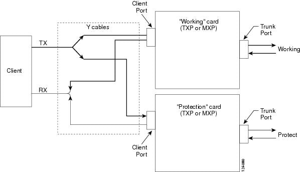
To set up Y-cable protection, create a Y-cable protection group for two TXP, MXP, or Xponder cards using Cisco Transport Controller (CTC). Next, connect the client ports of the two cards physically with a Y-cable. The single client signal is sent into the RX Y-cable and is split between the two TXP, MXP, or Xponder cards. The two TX signals from the client side of the TXP, MXP, or Xponder cards are combined in the TX Y-cable into a single client signal. Only the active card signal passes through as the single TX client signal. CTC automatically turns off the laser on the protect card to avoid signal interference where the Y-cable joins.
On the GE_XP, 10GE_XP, GE_XPE, 10GE_XPE, and OTU2_XP cards, the Y-cable protection mechanism is provisionable and can be set ON or OFF (OFF is the default mode).
When a signal fault is detected, the protection mechanism software automatically switches between paths. Y-cable protection also supports revertive and nonrevertive mode.
When an MXP_MR_2.5G, MXP_MR_10DME_C, MXP_MR_10DME_L, AR_MXP, AR_XP, or AR_XPE card that is provisioned with Y-cable protection is used on a storage ISL link (ESCON, FC1G, FC2G, FC4G, FICON1G, FICON2G, FICON4G, or ISC-3 1/2G), a protection switchover resets the standby port to active. This reset reinitialises the end-to-end link to avoid any link degradation caused due to loss of buffer credits during switchover and results in an end-to-end traffic hit of 15 to 20 seconds.
When using the MXP_MR_10DME_C or MXP_MR_10DME_L card, enable the fast switch feature and use it with a Cisco MDS storage switch to avoid this 15 to 20 second traffic hit. When enabling fast switch on the MXP_MR_10DME_C or MXP_MR_10DME_L card, ensure that the attached MDS switches have the buffer-to-buffer credit recovery feature enabled.
You can also use the TXP_MR_2.5G card to avoid this 15 to 20 second traffic hit. When a Y-cable protection switchover occurs, the storage ISL link does not reinitialize and results in an end-to-end traffic hit of less than 50 ms.
AR_MXP, AR_XP, and AR_XPE cards support Y-cable protection on the client ports, which are part of an unprotected card mode. The Y-cable protection is not supported for video and auto payloads.
When using the AR_MXP, AR_XP, or AR_XPE card on storage ISL link, use it with a Cisco MDS storage switch to avoid this 15 to 20 second traffic hit.
When the active AR_MXP, AR_XP, AR_XPE card is removed from a Cisco 15454 M2 or Cisco 15454 M6 shelf, there is a traffic hit of 60 to 100 ms.
Note![]() Y-cable connectors will not work with electrical SFPs because Y-cables are made up of optical connectors and it is not possible to physically connect them to an electrical SFP. Y-cable protection is not supported on IB_5G.
Y-cable connectors will not work with electrical SFPs because Y-cables are made up of optical connectors and it is not possible to physically connect them to an electrical SFP. Y-cable protection is not supported on IB_5G.
Note![]() There is a traffic hit of up to a of couple hundred milliseconds on the MXP_MR_2.5G and MXP_MR_10DME cards in Y-cable configuration when a fiber cut or SFP failure occurs on one of the client ports.
There is a traffic hit of up to a of couple hundred milliseconds on the MXP_MR_2.5G and MXP_MR_10DME cards in Y-cable configuration when a fiber cut or SFP failure occurs on one of the client ports.
Note![]() If you create a GCC on either card of the protect group, the trunk port stays permanently active, regardless of the switch state. When you provision a GCC, you are provisioning unprotected overhead bytes. The GCC is not protected by the protect group.
If you create a GCC on either card of the protect group, the trunk port stays permanently active, regardless of the switch state. When you provision a GCC, you are provisioning unprotected overhead bytes. The GCC is not protected by the protect group.
Figure G-14 shows the Y-cable signal flow.
Note![]() Loss of Signal–Payload (LOS-P) alarms, also called Incoming Payload Signal Absent alarms, can occur on a split signal if the ports are not in a Y-cable protection group.
Loss of Signal–Payload (LOS-P) alarms, also called Incoming Payload Signal Absent alarms, can occur on a split signal if the ports are not in a Y-cable protection group.
Note![]() Removing an SFP from the client ports of a card in a Y-cable protection group card causes an IMPROPRMVL (PPM) alarm. The working and protected port raises the IMPROPRMVL alarm. The severity on the client ports is changed according to the protection switch state.
Removing an SFP from the client ports of a card in a Y-cable protection group card causes an IMPROPRMVL (PPM) alarm. The working and protected port raises the IMPROPRMVL alarm. The severity on the client ports is changed according to the protection switch state.
Note![]() On the OTU2_XP card, when the 10G Ethernet LAN Phy to WAN Phy conversion feature is enabled, Y-cable protection is not supported on the LAN to WAN interface (ports 1 and 3).
On the OTU2_XP card, when the 10G Ethernet LAN Phy to WAN Phy conversion feature is enabled, Y-cable protection is not supported on the LAN to WAN interface (ports 1 and 3).
Note![]() When using fixed DWDM or tunable XFPs for Y-cable protection, the protection switch time may exceed 50 ms.
When using fixed DWDM or tunable XFPs for Y-cable protection, the protection switch time may exceed 50 ms.
Figure G-14 Y-Cable Protection
G.34.1.2 Splitter Protection
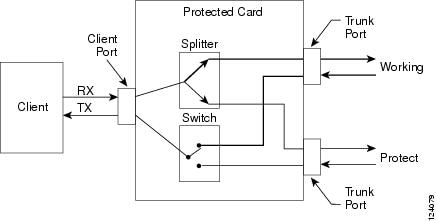
Splitter protection, shown in Figure G-15, is provided with TXPP cards, MXPP cards, and OTU2_XP cards (on trunk ports that are not part of a regenerator group). You can create and delete splitter protection groups in OTU2_XP card.
To implement splitter protection, a client injects a single signal into the client RX port. An optical splitter internal to the card then splits the signal into two separate signals and routes them to the two trunk TX ports. The two signals are transmitted over diverse optical paths. The far-end MXPP or TXPP card uses an optical switch to choose one of the two trunk RX port signals and injects it into the TX client port. When using splitter protection with two MXPP or TXPP cards, there are two different optical signals that flow over diverse paths in each direction. In case of failure, the far-end switch must choose the appropriate signal using its built-in optical switch. The triggers for a protection switch are LOS, LOF, SF, or SD.
In the splitter protected 10G Ethernet LAN Phy to WAN Phy mode, AIS-P and LOP-P acts as trigger (when G.709 is enabled) for the Protection Switch, in addition to the existing switching criteria.
In the OTU2_XP card, the STS parameters such as, SF /SD thresholds, Path PM thresholds, and Path Trace is set for the working path (Port 3). The same parameters are also applicable for the protected path (Port 4).
Figure G-15 Splitter Protection
G.34.2 1+1 Protection
The 1+1 protection is available for the GE_XP, GE_XPE, 10GE_XP, and 10GE_XPE cards:
The 1+1 protection is provided in the Layer 2 (L2) card mode to protect against client port and card failure. 1+1 protection is supported in both single shelf and multishelf setup. This means that the working card can be in one shelf and the protect card can be in another shelf of a multishelf setup. Communication between the two cards is across 10 Gigabit Ethernet interconnection interface using Ethernet packets. The Inter link (ILK) trunk or internal pathcord must be provisioned on both the cards. This link is used to transmit protection switching messages and data.
Note![]() With 1+1 protection mechanisms, the switch time of a copper SFP is 1 second.
With 1+1 protection mechanisms, the switch time of a copper SFP is 1 second.
With 1+1 protection, ports on the protect card can be assigned to protect the corresponding ports on the working card. A working card must be paired with a protect card of the same type and number of ports. The protection takes place on the port level, and any number of ports on the protect card can be assigned to protect the corresponding ports on the working card.
To make the 1+1 protection scheme fully redundant, enable L2 protection for the entire VLAN ring. This enables Fast Automatic Protection Switch (FAPS). The VLAN configured on the 1+1 port must be configured as protected SVLAN.
1+1 protection can be either revertive or nonrevertive. With nonrevertive 1+1 protection, when a failure occurs and the signal switches from the working card to the protect card, the signal remains on the protect card until it is manually changed. Revertive 1+1 protection automatically switches the signal back to the working card when the working card comes back online. 1+1 protection uses trunk ports to send control traffic between working and protect cards. This trunk port connection is known as ILK trunk ports and can be provisioned via CTC.
The standby port can be configured to turn ON or OFF but the traffic coming to and from the standby port will be down. If the laser is ON at the standby port, the other end port (where traffic originates) will not be down in a parallel connection. Traffic is blocked on the standby port.
1+1 protection is bidirectional and nonrevertive by default; revertive switching can be provisioned using CTC.
G.34.3 Layer 2 Over DWDM Protection
The Layer 2 Over DWDM protection is available for the following cards:
When the card is in L2-over-DWDM card mode, protection is handled by the hardware at the Layer 1 and Layer 2 levels. Fault detection and failure propagation is communicated through the ITU-T G.709 frame overhead bytes. For protected VLANs, traffic is flooded around the 10 Gigabit Ethernet DWDM ring. To set up the Layer 2 protection, you identify a node and the card port that is to serve as the master node and port for the VLAN ring on the card view Provisioning > Protection tab. If a failure occurs, the node and port are responsible for opening and closing VLAN loops.
Note![]() The Forced option in the Protection drop-down list converts all the SVLANs to protected SVLANs irrespective of the SVLAN protection configuration in the SVLAN database. This is applicable to a point-to-point linear topology. The SVLAN protection must be forced to move all SVLANs, including protected and unprotected SVLANs, to the protect path irrespective of provisioned SVLAN attributes.
The Forced option in the Protection drop-down list converts all the SVLANs to protected SVLANs irrespective of the SVLAN protection configuration in the SVLAN database. This is applicable to a point-to-point linear topology. The SVLAN protection must be forced to move all SVLANs, including protected and unprotected SVLANs, to the protect path irrespective of provisioned SVLAN attributes.
A FAPS switchover happens in the following failure scenarios:
- DWDM line failures caused by a fiber cut
- Unidirectional failure in the DWDM network caused by a fiber cut
- Fiber pull on the master card trunk port followed by a hard reset on the master card
- Hard reset on the master card
- Hard reset on the slave card
- An OTN failure is detected (LOS, OTUK-LOF, OTUK-LOM, OTUK-LOM, OTUK-SF, or OTUK-BDI on the DWDM receiver port in the case of ITU-T G.709 mode)
- Trunk ports are moved to OOS,DSBLD (Locked,disabled) state
- Improper removal of XFPs
A FAPS switchover does not happen in the following scenarios:
G.35 Far-End Laser Control
The 15454 DWDM cards provide a transparent mode that accurately conveys the client input signal to the far-end client output signal. The client signal is normally carried as payload over the DWDM signals. Certain client signals, however, cannot be conveyed as payload. In particular, client LOS or LOF cannot be carried. Far-end laser control (FELC) is the ability to convey an LOS or LOF from the near-end client input to the far-end client output.
If an LOS is detected on the near-end client input, the near-end trunk sets the appropriate bytes in the OTN overhead of the DWDM line. These bytes are received by the far-end trunk, and cause the far-end client laser to be turned off. When the laser is turned off, it is said to be squelched. If the near-end LOS clears, the near-end trunk clears the appropriate bytes in the OTN overhead, the far-end detects the changed bytes, and the far-end client squelch is removed.
FELC also covers the situation in which the trunk port detects that it has an invalid signal; the client is squelched so as not to propagate the invalid signal.
Payload types with the 2R mode preclude the use of OTN overhead bytes. In 2R mode, an LOS on the client port causes the trunk laser to turn off. The far end detects the LOS on its trunk receiver and squelches the client.
FELC is not provisionable. It is always enabled when the DWDM card is in transparent termination mode. However, FELC signaling to the far-end is only possible when ITU-T G.709 is enabled on both ends of the trunk span.
G.36 Jitter Considerations
Jitter introduced by the SFPs used in the transponders and muxponders must be considered when cascading several cards. With TXP_MR_2.5G, TXPP_MR_2.5G, MXP_MR_2.5G, MXPP_MR_2.5G, TXP_MR_10E, 100G-LC-C, 100G-ME-C, 10x10G-LC, CFP-LC, AR_MXP, AR_XP, AR_XPE cards several transponders can be cascaded before the cumulative jitter violates the jitter specification. The recommended limit is 20 cards. With TXP_MR_10G cards, you can also cascade several cards, although the recommended limit is 12 cards. With MXP_2.5G_10G and MXP_2.5G_10E cards, any number of cards can be cascaded as long as the maximum reach between any two is not exceeded. This is because any time the signal is demultiplexed, the jitter is eliminated as a limiting factor.
The maximum reach between one transponder and the other must be halved if a Y cable is used. For more information on Y-cable operation, see the “Y-Cable Protection” section.
G.37 Termination Modes
Transponder and muxponder cards have various SONET and SDH termination modes that can be configured using CTC (see the “Procedures for Transponder and Muxponder Cards” section). The termination modes are summarized in Table G-19 .
|
|
|
|
|---|---|---|
| All TXP, MXP, and OTU2_XP cards, with the exception of the MXP_2.5G_10G card (see next section of this table) |
All the bytes of the payload pass transparently through the cards. |
|
In line termination mode, the section and line overhead bytes for SONET and the overhead bytes for the SDH multiplex and regenerator sections are terminated. None of the overhead bytes are passed through. They are all regenerated, including the SONET SDCC and line DCC (LDCC) bytes and the SDH RS-DCC and multiplexer section DCC (MS-DCC) bytes. |
||
| MXP_2.5G_10G3 |
All client bytes pass transparently except the following: B1 is rebuilt, S1 is rewritten, A1 to A2 are regenerated, and H1 to H3 are regenerated. |
|
The SONET TOH section bytes and the SDH regenerator section overhead bytes are terminated. None of these section overhead bytes are passed through. They are all regenerated, including the SONET TOH section DCC bytes and the SDH RS-DCC bytes. In the section termination mode, the SONET TOH line and SDH multiplex section overhead bytes are passed transparently. |
||
In the line termination mode, the section and line overhead bytes for SONET and the overhead bytes for the SDH multiplex and regenerators sections are terminated. None of the overhead bytes are passed through. They are all regenerated, including the SONET SDCC and LDCC bytes and the SDH RS-DCC and MS-DCC bytes. |
|
3.Clients operating at the OC48/STM16 rate are multiplexed into an OC192/STM64 frame before going to OTN or DWDM. |
For TXP and MXP cards, adhere to the following conditions while DCC termination provisioning:
- For SDCC/RS-DCC provisioning, the card should be in the Section/RS-DCC or Line/MS-DCC termination mode.
- For LDCC/MS-DCC provisioning, the card should be in the Line/MS-DCC termination mode.
For more information on enabling termination modes, see the “Procedures for Transponder and Muxponder Cards” section.
 Feedback