- About this Guide
- Chapter 1, Install Shelf and Common Control Cards
- Chapter 2, Connect the PC and Log Into the GUI
- Chapter 3, Turn Up a Node
- Chapter 4, Perform Acceptance Tests
- Chapter 5, Turn Up a Network
- Chapter 6, Provision Channels and Circuits
- Chapter 7, Manage Alarms
- Chapter 8, Monitor Performance
- Chapter 9, Manage Node Settings
- Chapter 10, Change Card Settings
- Chapter 11, Maintain the Node
- Chapter 12, Power Down the Node
- Chapter 13, Shelf Hardware Reference
- Chapter 14, Card Reference
- Chapter 15, Node Reference
- Chapter 16, Network Reference
- Chapter 17, CTC Operation Reference
- Chapter 18, Security and Timing Reference
- Chapter 19, Network Connectivity Reference
- Chapter 20, Alarm Management Reference
- Appendix A, CTC Information and Shortcuts
- Appendix B, Shelf Specifications
- Appendix C, DWDM Extended State Model
Cisco Transport Controller Operation
This chapter describes Cisco Transport Controller (CTC), the software interface for the Cisco ONS 15454. For CTC setup and login information, refer to "Connect the PC and Log into the GUI."

Note ![]() Unless otherwise specified, "ONS 15454" refers to both ANSI and ETSI shelf assemblies.
Unless otherwise specified, "ONS 15454" refers to both ANSI and ETSI shelf assemblies.
Chapter topics include:
•![]() CTC Software Delivery Methods
CTC Software Delivery Methods
•![]() PC and UNIX Workstation Requirements
PC and UNIX Workstation Requirements
17.1 CTC Software Delivery Methods
ONS 15454 provisioning and administration is performed using the CTC software. CTC is a Java application that is installed in two locations: it is stored on the Advanced Timing, Communications, and Control (TCC2) card and it is downloaded to your workstation the first time you log into the ONS 15454 with a new software release.
17.1.1 CTC Software Installed on the TCC2 Card
CTC software is preloaded on the ONS 15454 TCC2 cards; therefore, you do not need to install software on the TCC2 cards. When a new CTC software version is released, use the release-specific software upgrade document to upgrade the ONS 15454 software on the TCC2 card.
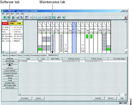
When you upgrade CTC software, the TCC2 cards store the new CTC version as the protect CTC version. When you activate the new CTC software, the TCC2 cards store the older CTC version as the protect CTC version, and the newer CTC release becomes the working version. You can view the software versions that are installed on an ONS 15454 by selecting the Maintenance > Software tabs in node view (Figure 17-1).
Figure 17-1 CTC Software Versions, Node View
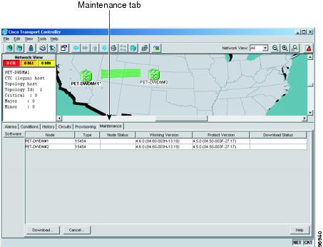
Select the Maintenance > Software tabs in network view to display the software versions installed on all the network nodes (Figure 17-2).
Figure 17-2 CTC Software Versions, Network View
17.1.2 CTC Software Installed on the PC or UNIX Workstation
CTC software is downloaded from the TCC2 cards and installed on your computer automatically after you connect to the ONS 15454 with a new software release for the first time. Downloading the CTC software files automatically ensures that your computer is running the same CTC software version as the TCC2 cards you are accessing. The CTC files are stored in the temporary directory designated by your computer operating system. You can use the Delete CTC Cache button to remove files stored in the temporary directory. If the files are deleted, they download the next time you connect to an ONS 15454. Downloading the Java archive (JAR) files for CTC takes several minutes depending on the bandwidth of the connection between your workstation and the ONS 15454. For example, JAR files downloaded from a modem or a data communications channel (DCC) network link require more time than JAR files downloaded over a LAN connection.
17.2 CTC Installation Overview
To connect to an ONS 15454 using CTC, you enter the ONS 15454 IP address in the URL field of Netscape Navigator or Microsoft Internet Explorer. After connecting to an ONS 15454, the following occurs automatically:
1. ![]() A CTC launcher applet is downloaded from the TCC2 card to your computer.
A CTC launcher applet is downloaded from the TCC2 card to your computer.
2. ![]() The launcher determines whether your computer has a CTC release matching the release on the ONS 15454 TCC2 card.
The launcher determines whether your computer has a CTC release matching the release on the ONS 15454 TCC2 card.
3. ![]() If the computer does not have CTC installed, or if the installed release is older than the TCC2 card's version, the launcher downloads the CTC program files from the TCC2 card.
If the computer does not have CTC installed, or if the installed release is older than the TCC2 card's version, the launcher downloads the CTC program files from the TCC2 card.
4. ![]() The launcher starts CTC. The CTC session is separate from the web browser session, so the web browser is no longer needed. Always log into nodes having the latest software release. If you log into an ONS 15454 that is connected to ONS 15454s with older versions of CTC, or to Cisco ONS 15327s or Cisco ONS 15600s, CTC files are downloaded automatically to enable you to interact with those nodes. The CTC file download occurs only when necessary, such as during your first login. You cannot interact with nodes on the network that have a software version later than the node that you used to launch CTC.
The launcher starts CTC. The CTC session is separate from the web browser session, so the web browser is no longer needed. Always log into nodes having the latest software release. If you log into an ONS 15454 that is connected to ONS 15454s with older versions of CTC, or to Cisco ONS 15327s or Cisco ONS 15600s, CTC files are downloaded automatically to enable you to interact with those nodes. The CTC file download occurs only when necessary, such as during your first login. You cannot interact with nodes on the network that have a software version later than the node that you used to launch CTC.
Each ONS 15454 can handle up to five concurrent CTC sessions. CTC performance can vary, depending upon the volume of activity in each session, network bandwidth, and TCC2 card load.
Note ![]() You can also use TL1 commands to communicate with the Cisco ONS 15454 through VT100 terminals and VT100 emulation software, or you can telnet to an ONS 15454 using TL1 port 3083. Refer to the Cisco ONS 15454 and Cisco ONS 15327 TL1 Command Guide for a comprehensive list of TL1 commands.
You can also use TL1 commands to communicate with the Cisco ONS 15454 through VT100 terminals and VT100 emulation software, or you can telnet to an ONS 15454 using TL1 port 3083. Refer to the Cisco ONS 15454 and Cisco ONS 15327 TL1 Command Guide for a comprehensive list of TL1 commands.
17.3 PC and UNIX Workstation Requirements
To use CTC for the ONS 15454, your computer must have a web browser with the correct Java Runtime Environment (JRE) installed. The correct JRE for each CTC software release is included on the Cisco ONS 15454 software CD and the ONS 15454 documentation CD. If you are running multiple CTC software releases on a network, the JRE installed on the computer must be compatible with the different software releases.
You can change the JRE version on the Preferences dialog box JRE tab. When you change the JRE version on the JRE tab, you must exit and restart CTC for the new JRE version to take effect. Table 17-1 shows JRE compatibility with ONS 15454 software releases.
|
|
|
|
|
|---|---|---|---|
ONS 15454 Release 2.2.1 and earlier |
Yes |
No |
No |
ONS 15454 Release 2.2.2 |
Yes |
Yes |
No |
ONS 15454 Release 3.0 |
Yes |
Yes |
No |
ONS 15454 Release 3.1 |
Yes |
Yes |
No |
ONS 15454 Release 3.2 |
Yes |
Yes |
No |
ONS 15454 Release 3.3 |
Yes |
Yes |
No |
ONS 15454 Release 3.4 |
No |
Yes |
No |
ONS 15454 Release 4.0 1 |
No |
Yes |
No |
ONS 15454 Release 4.1 |
No |
Yes |
No |
ONS 15454 Release 4.5 |
No |
Yes |
No |
ONS 15454 Release 4.6 |
No |
Yes |
Yes |
ONS 15454 Release 4.7 |
No |
No |
Yes |
1 Software Releases 4.0 and later notify you if an older version of the JRE is running on your PC or UNIX workstation. |
Table 17-2 lists the requirements for PCs and UNIX workstations. In addition to the JRE, the Java plug-in and modified java.policy file are also included on the ONS 15454 software CD and the ONS 15454 documentation CD.
17.4 ONS 15454 Connections
You can connect to the ONS 15454 in multiple ways. You can connect your PC directly to the ONS 15454 (local craft connection) using the RJ-45 port on the TCC2 card or, for the ANSI shelf, the LAN pins on the backplane (the ETSI shelf provides a LAN connection via the RJ-45 jack on the MIC-T/C/P FMEC). Alternatively, you can connect your PC to a hub or switch that is connected to the ONS 15454, connect to the ONS 15454 through a LAN or modem, or establish TL1 connections from a PC or TL1 terminal. Table 17-3 lists the ONS 15454 connection methods and requirements.
17.5 CTC Window
The CTC window appears after you log into an ONS 15454 (Figure 17-3). The window includes a menu bar, a toolbar, and a top and bottom pane. The top pane provides status information about the selected objects and a graphic of the current view. The bottom pane provides tabs and subtab to view ONS 15454 information and perform ONS 15454 provisioning and maintenance. From this window, you can display three ONS 15454 views: network, node, and card.
Figure 17-3 Node View (Default Login View)
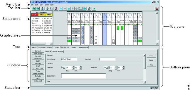
17.5.1 Node View
Node view, shown in Figure 17-3, is the first view that appears after you log into an ONS 15454. The login node is the first node shown, and it is the "home view" for the session. Node view allows you to manage one ONS 15454 node. The status area shows the node name; IP address; session boot date and time; number of Critical (CR), Major (MJ), and Minor (MN) alarms; name and security level of the current logged-in user; software version; and network element default setup.
17.5.1.1 CTC Card Colors
The graphic area of the CTC window depicts the ONS 15454 shelf assembly. The colors of the cards in the graphic reflect the real-time status of the physical card and slot (Table 17-4).
On the ONS 15454 ETSI, the colors of the Front Mount Electrical Connection (FMEC) cards reflect the real-time status of the physical FMEC cards. Table 17-5 lists the FMEC card colors. The FMEC ports shown in CTC do not change color.
Note ![]() You cannot preprovision FMECs.
You cannot preprovision FMECs.
The wording on a card in node view shows the status of a card (Active, Standby, Loading, or Not Provisioned). Table 17-6 lists the card statuses.
|
|
|
Sty |
Card is in standby mode. |
Act |
Card is active. |
NP |
Card is not present. |
Ldg |
Card is resetting. |
Port color in both card and node view indicates the port service state. Table 17-7 lists the port colors and their service states. For more information about port service states, refer to "DWDM Enhanced State Model."
|
|
|
|
|---|---|---|
Cyan (blue) |
Out-of-Service and Management, Loopback (OOS-MA,LPBK [ANSI]) Locked-enabled,loopback (ETSI) |
Port is in a loopback state. On the card in node view, a line between ports indicates that the port is in terminal or facility loopback (see Figure 17-4 and Figure 17-5). Traffic is carried and alarm reporting is suppressed. Raised fault conditions, whether or not their alarms are reported, can be retrieved on the CTC Conditions tab or by using the TL1 RTRV-COND command. |
Cyan (blue) |
Out-of-Service and Management, Maintenance (OOS-MA,MT [ANSI]) Locked-enabled,maintenance (ETSI) |
Port is out-of-service for maintenance. Traffic is carried and loopbacks are allowed. Alarm reporting is suppressed. Raised fault conditions, whether or not their alarms are reported, can be retrieved on the CTC Conditions tab or by using the TL1 RTRV-COND command. Use this service state for testing or to suppress alarms temporarily. Change the state to IS-NR/Unlocked-enabled; OOS-MA,DSBLD/Locked-enabled,disabled; or OOS-AU,AINS/Unlocked-disabled,automaticInService when testing is complete. |
Gray |
Out-of-Service and Management, Disabled (OOS-MA,DSBLD [ANSI]) Locked-enabled,disabled (ETSI) |
The port is out-of-service and unable to carry traffic. Loopbacks are not allowed in this service state. |
Green |
In-Service and Normal (IS-NR [ANSI]) Unlocked-enabled (ETSI) |
The port is fully operational and performing as provisioned. The port transmits a signal and displays alarms; loopbacks are not allowed. |
Violet |
Out-of-Service and Autonomous, Automatic In-Service (OOS-AU,AINS [ANSI]) Unlocked-disabled,automaticInService (ETSI) |
The port is out-of-service, but traffic is carried. Alarm reporting is suppressed. The node monitors the ports for an error-free signal. After an error-free signal is detected, the port stays in this service state for the duration of the soak period. After the soak period ends, the port service state changes to IS-NR/Unlocked-enabled. Raised fault conditions, whether or not their alarms are reported, can be retrieved on the CTC Conditions tab or by using the TL1 RTRV-COND command. The AINS port will automatically transition to IS-NR/Unlocked-enabled when a signal is received for the length of time provisioned in the soak field. |
Figure 17-4 Terminal Loopback Indicator

Figure 17-5 Facility Loopback Indicator

17.5.1.2 Node View Card Shortcuts
If you move your mouse over cards in the graphic, popups display additional information about the card including the card type; the card status (active or standby); the type of alarm, such as Critical, Major, or Minor (if any); the alarm profile used by the card; and for transponder (TXP) or muxponder (MXP) cards, the wavelength of the dense wavelength division multiplexing (DWDM) port. Right-click a card to reveal a shortcut menu, which you can use to open, reset, delete, or change a card. Right-click a slot to preprovision a card (that is, provision a slot before installing the card).
17.5.1.3 Node View Tabs
Table 17-8 lists the tabs and subtabs available in the node view.
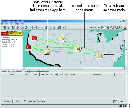
17.5.2 Network View
Network view allows you to view and manage ONS 15454s that have DCC connections to the node that you logged into and any login node groups you have selected (Figure 17-6).
Figure 17-6 Network in CTC Network View
Note ![]() Nodes with DCC connections to the login node do not appear if you checked the Disable Network Discovery check box in the Login dialog box.
Nodes with DCC connections to the login node do not appear if you checked the Disable Network Discovery check box in the Login dialog box.
The graphic area displays a background image with colored ONS 15454 icons. A Superuser can set up the logical network view feature, which enables each user to see the same network view.
The lines show DCC connections between the nodes (Table 17-9). DCC connections can be green (active) or gray (fail). The lines can also be solid (circuits can be routed through this link) or dashed (circuits cannot be routed through this link). Circuit provisioning uses active/routable links. Selecting a node or span in the graphic area displays information about the node and span in the status area.
The color of a node in network view, shown in Table 17-10, indicates the node alarm status.
Table 17-11 lists the tabs and subtabs available in network view.
17.5.3 Card View
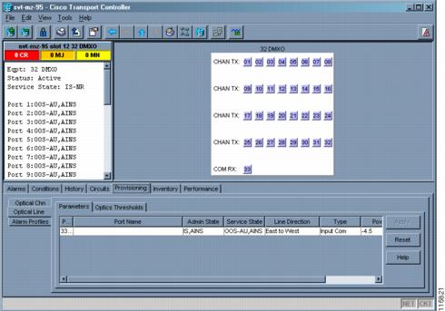
The card view provides information about individual ONS 15454 cards. Use this window to perform card-specific maintenance and provisioning (Figure 17-7). A graphic showing the ports on the card is shown in the graphic area. The status area displays the node name, slot, number of alarms, card type, equipment type, card status (active or standby), card service state if the card is present, and port service state (described in Table 17-7). The information that appears and the actions you can perform depend on the card. For more information about card service states, refer to "DWDM Enhanced State Model."
Figure 17-7 CTC Card View Showing a 32DMX-O Card
Note ![]() CTC provides a card view for all ONS 15454 cards except the TCC2 card.
CTC provides a card view for all ONS 15454 cards except the TCC2 card.
Use the card view tabs and subtabs shown in Table 17-12 to provision and manage the ONS 15454. The subtabs, fields, and information shown under each tab depend on the card type selected. The Performance tab is not available for the Alarm Interface Controller (AIC) or Alarm Interface Controller-International (AIC-I) cards.
17.6 TCC2 Card Reset
You can reset the ONS 15454 TCC2 card by using CTC (a soft reset) or by physically reseating a TCC2 card (a hard reset). A soft reset reboots the TCC2 card and reloads the operating system and the application software. Additionally, a hard reset temporarily removes power from the TCC2 card and clears all buffer memory.
You can apply a soft reset from CTC to either an active or standby TCC2 card without affecting traffic. If you need to perform a hard reset on an active TCC2 card, put the TCC2 card into standby mode first by performing a soft reset.
Note ![]() When a CTC reset is performed on an active TCC2 card, the AIC and AIC-I cards go through an initialization process and also reset because the AIC and AIC-I cards are controlled by the active TCC2.
When a CTC reset is performed on an active TCC2 card, the AIC and AIC-I cards go through an initialization process and also reset because the AIC and AIC-I cards are controlled by the active TCC2.
17.7 TCC2 Card Database
When dual TCC2 cards are installed in the ONS 15454, each TCC2 card hosts a separate database; therefore, the protect card database is available if the database on the working TCC2 fails. You can also store a backup version of the database on the workstation running CTC. This operation should be part of a regular ONS 15454 maintenance program at approximately weekly intervals, and should also be completed when preparing an ONS 15454 for a pending natural disaster, such as a flood or fire.
Note ![]() The following parameters are not backed up and restored: node name, IP address, mask and gateway, and Internet Inter-ORB Protocol (IIOP) port. If you change the node name and then restore a backed up database with a different node name, the circuits map to the new node name. Cisco recommends keeping a record of the old and new node names.
The following parameters are not backed up and restored: node name, IP address, mask and gateway, and Internet Inter-ORB Protocol (IIOP) port. If you change the node name and then restore a backed up database with a different node name, the circuits map to the new node name. Cisco recommends keeping a record of the old and new node names.
17.8 Software Revert
When you click the Activate button after a software upgrade, the TCC2 copies the current working database and saves it in a reserved location in the TCC2 flash memory. If you later need to revert to the original working software load from the protect software load, the saved database installs automatically. You do not need to restore the database manually or recreate circuits.
The revert feature is useful if a maintenance window closes while you are upgrading CTC software. You can revert to the protect software load without losing traffic. During the next maintenance window, complete the upgrade and activate the new software load.
Circuits created or provisioning done after a software load is activated (upgraded to a higher release) do not reinstate with a revert (for example, 4.0 to 3.4). The database configuration at the time of activation is reinstated after a revert. This does not apply to maintenance reverts (for example, 2.2.2 to 2.2.1), because maintenance releases use the same database.
 Feedback