- About this Guide
- Chapter 1, Install Shelf and Common Control Cards
- Chapter 2, Connect the PC and Log Into the GUI
- Chapter 3, Turn Up a Node
- Chapter 4, Perform Acceptance Tests
- Chapter 5, Turn Up a Network
- Chapter 6, Provision Channels and Circuits
- Chapter 7, Manage Alarms
- Chapter 8, Monitor Performance
- Chapter 9, Manage Node Settings
- Chapter 10, Change Card Settings
- Chapter 11, Maintain the Node
- Chapter 12, Power Down the Node
- Chapter 13, Shelf Hardware Reference
- Chapter 14, Card Reference
- Chapter 15, Node Reference
- Chapter 16, Network Reference
- Chapter 17, CTC Operation Reference
- Chapter 18, Security and Timing Reference
- Chapter 19, Network Connectivity Reference
- Chapter 20, Alarm Management Reference
- Appendix A, CTC Information and Shortcuts
- Appendix B, Shelf Specifications
- Appendix C, DWDM Extended State Model
DWDM Network Reference
This chapter explains the ONS 15454 dense wavelength division multiplexing (DWDM) network applications and topologies. The chapter also provides network-level optical performance references.

Note ![]() Unless otherwise specified, "ONS 15454" refers to both ANSI and ETSI shelf assemblies.
Unless otherwise specified, "ONS 15454" refers to both ANSI and ETSI shelf assemblies.
Chapter topics include:
•![]() Network Optical Safety - Automatic Laser Shutdown
Network Optical Safety - Automatic Laser Shutdown
16.1 Network Applications
Cisco ONS 15454s can be provisioned for metro access and metro core DWDM network applications. Metro access networks are 60 km or less in size. Channels are not equalized and dispersion compensation is not applied. Metro access networks have few spans and very low span loss, so the signal link budget is the limiting factor for performance. Metro core networks can be up to 400 km in size. The channel power is equalized and dispersion compensation is applied. Metro core networks often include multiple spans and amplifiers, so the optical signal-to-noise ratio (OSNR) is the limiting factor for channel performance in metro core networks.
Within DWDM networks, the ONS 15454 uses a communications protocol, called node services protocol (NSP), to communicate with other nodes. NSP automatically updates nodes whenever a change in the network occurs. Each ONS 15454 DWDM node can:
•![]() Identify other ONS 15454 DWDM nodes in the network.
Identify other ONS 15454 DWDM nodes in the network.
•![]() Identify the different types of DWDM networks.
Identify the different types of DWDM networks.
•![]() Identify when the DWDM network is complete and when it is incomplete.
Identify when the DWDM network is complete and when it is incomplete.
16.2 Network Topologies
The ONS 15454 DWDM network topologies include hubbed, multihubbed, and meshed rings, and linear and single-span networks
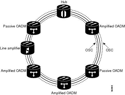
16.2.1 Hubbed Rings
In the hubbed ring topology (Figure 16-1), a hub node terminates all the DWDM channels. A channel can be provisioned to support protected traffic between the hub node and any node in the ring. Both working and protected traffic use the same wavelength on both sides of the ring. Protected traffic can also be provisioned between any pair of optical add/drop multiplexing (OADM) nodes, except that either the working or the protected path must be regenerated in the hub node.
Protected traffic saturates a channel in a hubbed ring, that is, no channel reuse is possible. However, the same channel can be reused in difference sections of the ring by provisioning unprotected multihop traffic. From a transmission point of view, this network topology is similar to two bidirectional point-to-point links with OADM nodes.
For more information about hub nodes, see the "15.1.1 Hub Node" section on page 15-1.
Figure 16-1 Hubbed Ring
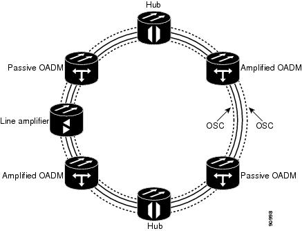
16.2.2 Multihubbed Rings
A multihubbed ring (Figure 16-2) is based on the hubbed ring topology, except that two or more hub nodes are added. Protected traffic can only be established between the two hub nodes. Protected traffic can be provisioned between a hub node and any OADM node only if the allocated wavelength channel is regenerated through the other hub node. Multihop traffic can be provisioned on this ring. From a transmission point of view, this network topology is similar to two or more point-to-point links with OADM nodes.
Figure 16-2 Multihubbed Ring
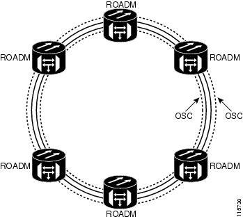
16.2.3 Any-to-Any Rings
The any-to-any ring topology (Figure 16-2) contains only reconfigurable OADM (ROADM) nodes, or ROADM nodes with Optical Service Channel (OSC) regeneration or amplifier nodes. This topology potentially allows you to route every wavelength from any source to any destination node inside the network.
For more information about ROADM nodes, see the "15.1.4 ROADM Node" section on page 15-8.
Figure 16-3 Any-to-Any Ring
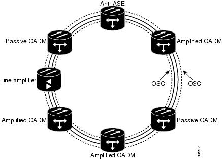
16.2.4 Meshed Rings
The meshed ring topology (Figure 16-4) does not use hubbed nodes; only amplified and passive OADM nodes are present. Protected traffic can be provisioned between any two nodes; however, the selected channel cannot be reused in the ring. Unprotected multihop traffic can be provisioned in the ring. A meshed ring must be designed to prevent amplified spontaneous emission (ASE) lasing. This is done by configuring a particular node as an anti-ASE node. An anti-ASE node can be created in two ways:
•![]() Equip an OADM node with 32MUX-O cards and 32DMX-O cards. This solution is adopted when the total number of wavelengths deployed in the ring is higher than ten. OADM nodes equipped with 32MUX-O cards and 32DMX-O cards are called full OADM nodes.
Equip an OADM node with 32MUX-O cards and 32DMX-O cards. This solution is adopted when the total number of wavelengths deployed in the ring is higher than ten. OADM nodes equipped with 32MUX-O cards and 32DMX-O cards are called full OADM nodes.
•![]() When the total number of wavelengths deployed in the ring is lower than ten, the anti-ASE node is configured by using an OADM node where all the channels that are not terminated in the node are configured as "optical pass-through." In other words, no channels in the anti-ASE node can travel through the express path of the OADM node.
When the total number of wavelengths deployed in the ring is lower than ten, the anti-ASE node is configured by using an OADM node where all the channels that are not terminated in the node are configured as "optical pass-through." In other words, no channels in the anti-ASE node can travel through the express path of the OADM node.
For more information about OADM nodes, see the "15.1.3 OADM Node" section on page 15-4. For more information about anti-ASE nodes, see the "15.1.5 Anti-ASE Node" section on page 15-10.
Figure 16-4 Meshed Ring
16.2.5 Linear Configurations
Linear configurations are characterized by the use of two terminal nodes (west and east). The terminal nodes can be equipped with a 32MUX-O card and a 32DMX-O card, or a 32WSS card with 32DMX or 32DMX-O card. OADM or line amplifier nodes can be installed between the two terminal nodes. Only unprotected traffic can be provisioned in a linear configuration. Figure 16-5 shows five ONS 15454 nodes in a linear configuration with an amplified and a passive OADM node.
Figure 16-5 Linear Configuration with an OADM Node
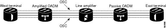
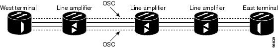
Figure 16-6 shows five ONS 15454 nodes in a linear configuration without an OADM node.
For more information about terminal nodes, see the "15.1.2 Terminal Node" section on page 15-3.
Figure 16-6 Linear Configuration without an OADM Node
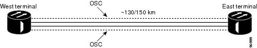
16.2.6 Single-Span Link
Single-span link is a type of linear configuration characterized by a single-span link with pre-amplification and post-amplification. A single-span link is also characterized by the use of two terminal nodes (west and east). The terminal nodes are usually equipped with a 32MUX-O card and a 32DMX-O card. However, a 32WSS card and a 32DMX or a 32DMX-O card can be installed. Software R4.7 also supports single-span links with AD-4C-xx.x cards. Only unprotected traffic can be provisioned on a single-span link.
Figure 16-7 shows ONS 15454s in a single-span link. Eight channels are carried on one span. Single-span link losses apply to OC-192 LR ITU cards. The optical performance values are valid assuming that the sum of the OADM passive node insertion losses and the span losses does not exceed 35 dB.
Figure 16-7 Single-Span Link
16.3 Optical Performance
This section provides optical performance information for ONS 15454 DWDM networks. The performance data is a general guideline based upon the network topology, node type, client cards, fiber type, number of spans, and number of channels. The maximum number of nodes that can be in an ONS 15454 DWDM network is 16. The DWDM topologies and node types that are supported are shown in Table 16-1.
|
|
|
|
|
|---|---|---|---|
32 channels |
SMF-281 E-LEAF2 TW-RS3 |
Ring Linear Linear without OADM |
Hub Active OADM Passive OADM Terminal Line OSC regeneration |
16 channels |
SMF-28 |
Ring Linear Linear without OADM |
Hub Active OADM Passive OADM Terminal Line OSC regeneration |
8 channels |
SMF-28 |
Linear without OADM |
Terminal Line |
1 SMF-28 = single-mode fiber 28 2 E-LEAF = enhanced large effective area fiber 3 TW-RS = TrueWave reduced slope fiber |
DWDM client cards are grouped into nine classes, shown in Table 16-2. Span loss estimates are based on the number of spans in the network and the client card class. Some cards belong to more than one class depending on whether forward error correction (FEC) is enabled and on the payload data type provisioned for the card.
|
|
|
|
|---|---|---|
A |
10 Gbps |
TXP_2.5G_10G—FEC enabled TXP_2.5G_10E—FEC enabled TXP_MR_10G—FEC enabled TXP_MR_10E—FEC enabled |
B |
10 Gbps |
TXP_2.5G_10G—FEC not enabled TXP_MR_10G—FEC not enabled |
C |
10 Gbps |
OC-192 LR ITU TXP_2.5G_10E—FEC not enabled |
D |
2.5 Gbps |
TXP_MR_2.5G—FEC enabled TXPP_MR_2.5G—FEC enabled |
E |
2.5 Gbps |
TXP_MR_2.5G—3R payload data type; FEC disabled TXPP_MR_2.5G—3R payload data type; FEC disabled MXP_MR_2.5G MXPP_MR_2.5G |
F |
2.5 Gbps |
TXP_MR_2.5G—2R payload data type TXPP_MR_2.5G—2R payload data type |
G |
2.5 Gbps |
OC-48 ELR ITU |
H |
2.5 Gbps |
2/4 port Gigabit Ethernet Transponder (GBIC WDM 100 GHz) |
I |
10 Gbps |
TXP_2.5G_10E—E-FEC1 enabled TXP_MR_10E—E-FEC enabled |
1 Forward error correction |
16.3.1 Optical Performance for Rings and Linear Networks with OADM Nodes
The following tables provide optical performance estimates for open and closed ONS 15454 rings and linear networks with OADM nodes. Table 16-3 shows the optical performance for 32-channel networks using SMF fiber. Span losses shown in the table assume:
•![]() OADM nodes have a loss of 16 dB and equal span losses.
OADM nodes have a loss of 16 dB and equal span losses.
•![]() Optical Preamplifier (OPT-PRE) and Optical Booster (OPT-BST/OPT-BST-E) amplifiers are installed in all nodes.
Optical Preamplifier (OPT-PRE) and Optical Booster (OPT-BST/OPT-BST-E) amplifiers are installed in all nodes.
•![]() The OPT-PRE amplifier switches to control power whenever the span loss is higher than 27 dB.
The OPT-PRE amplifier switches to control power whenever the span loss is higher than 27 dB.
Note ![]() See Table 16-2 for a list of cards in each class. A dash (—) indicates spans that are not supported.
See Table 16-2 for a list of cards in each class. A dash (—) indicates spans that are not supported.
|
|
|
|
||||||||
|---|---|---|---|---|---|---|---|---|---|---|
|
|
|
|
|
|
|
|
|
|
|
|
1 |
34 dB |
26 dB |
26 dB |
36 dB |
37 dB |
33 dB |
30 dB |
32 dB |
34 dB |
30 dB |
2 |
28 dB |
21 dB |
20 dB |
30 dB |
31 dB |
28 dB |
25 dB |
27 dB |
29 dB |
25 dB |
3 |
26 dB |
17 dB |
15 dB |
28 dB |
29 dB |
26 dB |
23 dB |
25 dB |
26 dB |
23 dB |
4 |
24 dB |
— |
— |
25 dB |
26 dB |
23 dB |
20 dB |
22 dB |
24 dB |
20 dB |
5 |
22 dB |
— |
— |
24 dB |
25 dB |
22 dB |
16 dB |
20 dB |
23 dB |
16 dB |
6 |
20 dB |
— |
— |
22 dB |
24 dB |
19 dB |
— |
17 dB |
21 dB |
— |
7 |
181 dB |
— |
— |
21 dB |
23 dB |
16 dB |
— |
— |
19 dB |
— |
1 0.5 dB of OSNR impairment recovered by FEC margin @ BER > 10-6 |
Table 16-4 shows the optical performance for 16-channel networks using SMF fiber. Span loss values assume the following:
•![]() OADM nodes have a loss of 16 dB and equal span losses.
OADM nodes have a loss of 16 dB and equal span losses.
•![]() All nodes have OPT-PRE and OPT-BST/OPT-BST-E amplifiers installed.
All nodes have OPT-PRE and OPT-BST/OPT-BST-E amplifiers installed.
•![]() The OPT-PRE amplifier switches to control power whenever the span loss is higher than 27 dB.
The OPT-PRE amplifier switches to control power whenever the span loss is higher than 27 dB.
Note ![]() See Table 16-2 for client card class definitions. A dash (—) indicates the spans are not available for that client class.
See Table 16-2 for client card class definitions. A dash (—) indicates the spans are not available for that client class.
Table 16-5 shows the optical performance for 32-channel networks using TW-RS fiber. Span loss values assume the following:
•![]() OADM nodes have a loss of 16 dB and equal span losses.
OADM nodes have a loss of 16 dB and equal span losses.
•![]() All nodes have OPT-PRE and OPT-BST/OPT-BST-E amplifiers installed.
All nodes have OPT-PRE and OPT-BST/OPT-BST-E amplifiers installed.
•![]() The OPT-PRE amplifier switches to control power whenever the span loss is higher than 27 dB.
The OPT-PRE amplifier switches to control power whenever the span loss is higher than 27 dB.
Note ![]() See Table 16-2 for client card class definitions. A dash (—) indicates the spans are not available for that client class.
See Table 16-2 for client card class definitions. A dash (—) indicates the spans are not available for that client class.
Table 16-6 shows the optical performance for 32-channel networks using E-LEAF fiber. Span loss values assume the following:
•![]() OADM nodes have a loss of 16 dB and equal span losses.
OADM nodes have a loss of 16 dB and equal span losses.
•![]() All nodes have OPT-PRE and OPT-BST/OPT-BST-E amplifiers installed.
All nodes have OPT-PRE and OPT-BST/OPT-BST-E amplifiers installed.
•![]() The OPT-PRE amplifier switches to control power whenever the span loss is higher than 27 dB.
The OPT-PRE amplifier switches to control power whenever the span loss is higher than 27 dB.
Note ![]() See Table 16-2 for client card class definitions. A dash (—) indicates the spans are not available for that client class.
See Table 16-2 for client card class definitions. A dash (—) indicates the spans are not available for that client class.
16.3.2 Optical Performance for Linear Networks Without OADM Nodes
The following tables list the reference optical performances for linear networks without OADM nodes. Table 16-7 shows the optical performance for 32-channel linear networks using SMF fiber. Span loss values assume the following:
•![]() No OADM nodes are installed.
No OADM nodes are installed.
•![]() Only OPT-PRE amplifiers are installed.
Only OPT-PRE amplifiers are installed.
•![]() Span losses are equal.
Span losses are equal.
Note ![]() See Table 16-2 for client card class definitions. A dash (—) indicates the spans are not available for that client class.
See Table 16-2 for client card class definitions. A dash (—) indicates the spans are not available for that client class.
Table 16-8 shows the optical performance for 32-channel linear networks using TW-RS fiber. Span loss values assume the following:
•![]() No OADM nodes are installed.
No OADM nodes are installed.
•![]() Only OPT-PRE amplifiers are installed.
Only OPT-PRE amplifiers are installed.
•![]() Span losses are equal.
Span losses are equal.
Note ![]() See Table 16-2 for client card class definitions. A dash (—) indicates the spans are not available for that client class.
See Table 16-2 for client card class definitions. A dash (—) indicates the spans are not available for that client class.
Table 16-9 shows the optical performance for 32-channel linear networks using E-LEAF fiber. Span loss values assume the following:
•![]() No OADM nodes are installed.
No OADM nodes are installed.
•![]() Only OPT-PRE amplifiers are installed.
Only OPT-PRE amplifiers are installed.
•![]() Span losses are equal.
Span losses are equal.
Note ![]() See Table 16-2 for client card class definitions. A dash (—) indicates the spans are not available for that client class.
See Table 16-2 for client card class definitions. A dash (—) indicates the spans are not available for that client class.
Table 16-10 shows the optical performance for 16-channel linear networks using SMF fiber. Span loss values assume the following:
•![]() No OADM nodes are installed.
No OADM nodes are installed.
•![]() Only OPT-PRE amplifiers are installed.
Only OPT-PRE amplifiers are installed.
•![]() Span losses are equal.
Span losses are equal.
•![]() The minimum channel power is 4 dBm.
The minimum channel power is 4 dBm.
•![]() Wavelengths are picked up without any restriction from Bands 4 and 5 (1542.14 to 1545.51 nm).
Wavelengths are picked up without any restriction from Bands 4 and 5 (1542.14 to 1545.51 nm).
Note ![]() See Table 16-2 for client card class definitions.
See Table 16-2 for client card class definitions.
Table 16-11 shows the optical performance for 8-channel linear networks using SMF fiber. Span loss values assume the following:
•![]() No OADM nodes are installed.
No OADM nodes are installed.
•![]() Only OPT-PRE amplifiers are installed.
Only OPT-PRE amplifiers are installed.
•![]() Span losses are equal.
Span losses are equal.
Note ![]() See Table 16-2 for client card class definitions. A dash (—) indicates the spans are not available for that client class.
See Table 16-2 for client card class definitions. A dash (—) indicates the spans are not available for that client class.
16.3.3 Optical Performance for ROADM Rings and Linear Networks
The following tables list the reference optical performances for ROADM rings and linear networks. Table 16-12 shows the optical performance for 32-channel linear or ring networks using SMF fiber with only ROADM nodes installed. Span loss values assume the following:
•![]() All nodes in the ring or linear network are ROADM.
All nodes in the ring or linear network are ROADM.
•![]() OPT-PRE and OPT-BST/OPT-BST-E amplifiers are installed.
OPT-PRE and OPT-BST/OPT-BST-E amplifiers are installed.
•![]() Span losses are equal.
Span losses are equal.
Note ![]() See Table 16-2 for client card class definitions. A dash (—) indicates spans that are not available for that client class.
See Table 16-2 for client card class definitions. A dash (—) indicates spans that are not available for that client class.
Table 16-13 shows the optical performance for 32-channel linear or ring network with ROADM and OADM nodes using SMF fiber. Span loss values assume the following:
•![]() All nodes in the ring or linear network are ROADM or OADM.
All nodes in the ring or linear network are ROADM or OADM.
•![]() OPT-PRE and OPT-BST/OPT-BST-E amplifiers are installed.
OPT-PRE and OPT-BST/OPT-BST-E amplifiers are installed.
•![]() Span losses are equal.
Span losses are equal.
Note ![]() See Table 16-2 for client card class definitions. A dash (—) indicates spans that are not available for that client class.
See Table 16-2 for client card class definitions. A dash (—) indicates spans that are not available for that client class.
|
|
|
|
||||||||
|---|---|---|---|---|---|---|---|---|---|---|
|
|
|
|
|
|
|
|
|
|
|
|
1 |
30 dB |
23 dB |
24 dB |
31 dB |
34 dB |
31 dB |
28 dB |
29 dB |
30 dB |
28 dB |
2 |
26 dB |
19 dB |
19 dB |
27 dB |
27 dB |
26 dB |
23 dB |
26 dB |
27 dB |
23 dB |
3 |
23 dB |
— |
— |
25 dB |
26 dB |
23 dB |
21 dB |
23 dB |
24 dB |
21 dB |
4 |
21 dB |
— |
— |
23 dB |
24 dB |
22 dB |
18 dB |
21 dB |
22 dB |
18 dB |
5 |
20 dB |
— |
— |
22 dB |
23 dB |
20 dB |
13 dB |
20 dB |
21 dB |
13 dB |
6 |
17 dB |
— |
— |
19 dB |
22 dB |
18 dB |
— |
17 dB |
18 dB |
— |
7 |
151 dB |
— |
— |
17 dB |
21 dB |
16 dB |
— |
151 |
16 dB |
— |
1 0.5 dB of OSNR impairment recovered by FEC margin @ BER>10-6 |
The following tables show the pass/fail criteria for eight and sixteen ROADM nodes. Table 16-14 shows the pass/fail criteria for eight ROADM nodes (seven spans) required for any-to-any node circuit reconfigurations:
•![]() All nodes in the ring are ROADM.
All nodes in the ring are ROADM.
•![]() Span losses are equal.
Span losses are equal.
Note ![]() See Table 16-2 for client card class definitions. A dash (—) indicates spans that are not available for that client class.
See Table 16-2 for client card class definitions. A dash (—) indicates spans that are not available for that client class.
Table 16-15 shows the pass/fail criteria for 16 ROADM nodes (15 spans) required for any-to-any node circuit reconfigurations.
•![]() All nodes in the ring are ROADM.
All nodes in the ring are ROADM.
•![]() Span losses are equal.
Span losses are equal.
Note ![]() See Table 16-2 for client card class definitions. A dash (—) indicates spans that are not available for that client class.
See Table 16-2 for client card class definitions. A dash (—) indicates spans that are not available for that client class.
|
|
|
|
|
||||||||
|---|---|---|---|---|---|---|---|---|---|---|---|
|
|
|
|
|
|
|
|
|
|
|
||
1 |
OPT-PRE only |
<151 |
<151 |
<151 |
Yes |
Yes |
<151 |
<151 |
<151 |
<151 |
— |
2 |
OPT-PRE only |
<151 |
<151 |
<151 |
Yes |
Yes |
<151 |
<151 |
<151 |
<151 |
— |
3 |
OPT-PRE only |
<151 |
<151 |
<151 |
Yes |
Yes |
<151 |
<151 |
<151 |
<151 |
— |
4 |
OPT-PRE only |
<151 |
<151 |
<151 |
Yes |
Yes |
<151 |
<151 |
<151 |
<151 |
— |
5 |
OPT-PRE only |
<151 |
<151 |
<151 |
Yes |
Yes |
<151 |
<151 |
<151 |
<151 |
— |
6 |
OPT-PRE only |
<151 |
<151 |
<151 |
Yes |
Yes |
<151 |
<151 |
<151 |
<151 |
— |
7 |
OPT-PRE and OPT-BST/OPT-BST-E |
<151 |
<151 |
<151 |
Yes |
Yes |
<151 |
<151 |
<151 |
<151 |
— |
8 |
OPT-PRE and OPT-BST/OPT-BST-E |
<151 |
<151 |
<151 |
Yes |
Yes |
<151 |
<151 |
<151 |
<151 |
— |
9 |
OPT-PRE and OPT-BST/OPT-BST-E |
<151 |
<151 |
<151 |
Yes |
Yes |
<151 |
<151 |
<151 |
<151 |
— |
10 |
OPT-PRE and OPT-BST/OPT-BST-E |
<151 |
<151 |
<151 |
Yes |
Yes |
<151 |
<151 |
<151 |
<151 |
— |
11 |
OPT-PRE and OPT-BST/OPT-BST-E |
<151 |
<151 |
<151 |
Yes |
Yes |
<151 |
<151 |
<151 |
<151 |
— |
12 |
OPT-PRE and OPT-BST/OPT-BST-E |
<151 |
<151 |
<151 |
Yes |
Yes |
<151 |
<151 |
<151 |
<151 |
— |
13 |
OPT-PRE and OPT-BST/OPT-BST-E |
<151 |
<151 |
<151 |
Yes |
Yes |
<151 |
<151 |
<151 |
<151 |
— |
14 |
OPT-PRE and OPT-BST/OPT-BST-E |
<151 |
<151 |
<151 |
Yes |
Yes |
<151 |
<151 |
<151 |
<151 |
— |
15 |
OPT-PRE and OPT-BST/OPT-BST-E |
<151 |
<151 |
<151 |
Yes |
Yes |
<151 |
<151 |
<151 |
<151 |
— |
1 Cisco MetroPlanner calculates the maximum ring circumference and number of nodes that can be supported. |
16.3.4 Optical Performance for Single-Span Networks
Table 16-16 lists the span loss for a single-span link configuration with eight channels. The optical performance for this special configuration is given only for Classes A and C. This configuration assumes a maximum channel capacity of eight channels (8-dBm nominal channel power) used without any restrictions on the 32 available channels.
Table 16-17 lists the span loss for a single-span link configuration with 16 channels. The optical performance for this special configuration is given only for Class A and Class C. This configuration assumes a maximum channel capacity of 16 channels (5-dBm nominal channel power) used without any restrictions on the 32 available channels.
Table 16-18 lists the span loss for a single-span link configuration with AD-1C-x.xx cards, OPT-PRE amplifiers, and OPT-BST/OPT-BST-E amplifiers. The single-span link with a flexible channel count is used both for transmitting and receiving. If dispersion compensation is required, a DCU can be used with an OPT-PRE amplifier. The optical performance for this special configuration is given for Classes A through G (8-dBm nominal channel power) used without any restrictions on the 32 available channels.
|
|
|
|
|
|||||
|---|---|---|---|---|---|---|---|---|
|
|
|
|
|
|
|
|
||
With OSCM cards1 |
1 |
37 dB |
31 dB |
31 dB |
37 dB |
37 dB |
37 dB |
37 dB |
Hybrid with OSC-CSM cards2 |
1 |
35 dB |
31 dB |
31 dB |
35 dB |
35 dB |
35 dB |
35 dB |
1 OSCM sensitivity limits the performance to 37 dB. 2 OSC-CSM sensitivity limits the performance to 35 dB when it replaces the OSCM. |
Table 16-19 lists the span loss for a single-span link configuration with one channel and OPT-BST/OPT-BST-E amplifiers. The optical performance for this special configuration is given for Classes A through G. Classes A, B, and C use 8-dBm nominal channel power. Classes D, E, F, and G use 12-dBm nominal channel power. There are no restriction on the 32 available channels. That is, a line card, transponder, or muxponder wavelength can be extracted from the 32 available wavelengths. Also, the optical service channel is not required.
Table 16-20 lists the span loss for a single-span link configuration with one channel, OPT-BST/OPT-BST-E amplifiers, OPT-PRE amplifiers, and ONS 15216 FlexLayer filters. ONS 15216 FlexLayer filters are used instead of the AD-1C-xx.x cards to reduce equipment costs and increase the span length, since the optical service channel is not necessary. The optical performance for this special configuration is given for Classes A through G. Classes A, B, and C use 8-dBm nominal channel power. Classes D, E, F, and G use 12-dBm nominal channel power. There are no restriction on the first 16 available wavelengths (from 1530.33 to 1544.53 nm).
16.4 Network Optical Safety - Automatic Laser Shutdown
Automatic laser shutdown (ALS) is a technique used to automatically shut down the output power of laser transmitters and optical amplifiers in the event of a fiber break. Cards with laser transmitters can be provisioned as follows with respect to ALS:
•![]() Disable: ALS is off; the laser is not automatically shut down when a traffic outage loss of signal (LOS) occurs
Disable: ALS is off; the laser is not automatically shut down when a traffic outage loss of signal (LOS) occurs
•![]() Auto Restart: ALS is on. The laser automatically shuts down when traffic outages (LOS) occur. It automatically restarts when the conditions that caused the outage are resolved.
Auto Restart: ALS is on. The laser automatically shuts down when traffic outages (LOS) occur. It automatically restarts when the conditions that caused the outage are resolved.
Note ![]() Auto Restart is the default ALS provisioning
Auto Restart is the default ALS provisioning
•![]() Manual Restart: ALS is on. The laser automatically shuts down when traffic outages (LOS) occur. However, the laser must be manually restarted when conditions that caused the outage are resolved.
Manual Restart: ALS is on. The laser automatically shuts down when traffic outages (LOS) occur. However, the laser must be manually restarted when conditions that caused the outage are resolved.
•![]() Manual Restart for Test: Manually restarts the laser for testing.
Manual Restart for Test: Manually restarts the laser for testing.
In the following paragraphs, two ALS scenarios are given:
•![]() Nodes using OPT-BT cards (amplified nodes)
Nodes using OPT-BT cards (amplified nodes)
•![]() Nodes using OSC-CSM cards (passive nodes)
Nodes using OSC-CSM cards (passive nodes)
16.4.1 Scenario 1: Fiber Cut in Nodes Using OPT-BST or OPT-BST-E Cards
Figure 16-8 shows nodes using OPT-BST or OPT-BST-E cards with a fiber cut between them.
Figure 16-8 Nodes Using OPT-BST/OPT-BST-E Cards
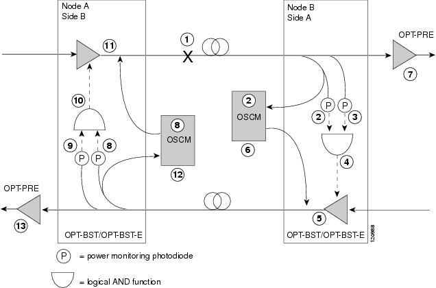
Two photodiodes at Node B monitor the received signal strength for the optical payload and optical service channel (OSC) signals. When the fiber is cut, a loss of signal (LOS) is detected at both of the photodiodes. The AND function then indicates an overall LOS condition, which causes the OPT-BST/OPT-BST-E transmitter, OPT-PRE transmitter, and OSCM lasers to shut down. This in turn leads to a LOS for both the optical payload and OSC at Node A, which causes Node A to turn off the OSCM, OPT-PRE transmitter, and OPT-BST/OPT-BST-E transmitter lasers. The sequence of events after a fiber cut is as follows (refer to the numbered circles in Figure 16-8):
1. ![]() Fiber is cut
Fiber is cut
2. ![]() Power monitoring photodiode detects a LOS on the OSC and OSCM detects LOS
Power monitoring photodiode detects a LOS on the OSC and OSCM detects LOS
3. ![]() Power monitoring photodiode detects a LOS for the optical payload
Power monitoring photodiode detects a LOS for the optical payload
4. ![]() LOS is declared
LOS is declared
5. ![]() The OPT-BST/OPT-BST-E amplifier laser is shut down in less than three seconds
The OPT-BST/OPT-BST-E amplifier laser is shut down in less than three seconds
6. ![]() The OSCM laser is shut down
The OSCM laser is shut down
7. ![]() The OPT-PRE laser is shut down
The OPT-PRE laser is shut down
8. ![]() Power monitoring photodiode detects a LOS on the OSC and OSCM detects LOS
Power monitoring photodiode detects a LOS on the OSC and OSCM detects LOS
9. ![]() Power monitoring photodiode detects a LOS for the optical payload
Power monitoring photodiode detects a LOS for the optical payload
10. ![]() LOS is declared
LOS is declared
11. ![]() The OPT-BST/OPT-BST-E amplifier laser is shut down
The OPT-BST/OPT-BST-E amplifier laser is shut down
12. ![]() The OSCM laser is shut down
The OSCM laser is shut down
13. ![]() The OPT-PRE laser is shut down
The OPT-PRE laser is shut down
When the fiber is repaired, either an automatic or manual restart at the Node A OPT-BST/OPT-BST-E transmitter or at the Node B OPT-BST/OPT-BST-E transmitter is required. A system that has been shut down is reactivated through the use of a restart pulse. The pulse is used to signal that the optical path has been restored and transmission can begin. For example, when the far end, Node B, receives a pulse, it signals to the Node B OPT-BST/OPT-BST-E transmitter to begin transmitting an optical signal. The OPT-BST/OPT-BST-E receiver at Node A receives that signal and signals the Node A OPT-BST/OPT-BST-E transmitter to resume transmitting.
Note ![]() During a laser restart pulse, automatic power reduction (APR) is disabled and the laser power does not exceed Class 1 limits.
During a laser restart pulse, automatic power reduction (APR) is disabled and the laser power does not exceed Class 1 limits.
16.4.2 Scenario 2: Fiber Cut in Nodes Using OSC-CSM Cards
Figure 16-9 shows nodes using OSC-CSM cards with a fiber cut between them.
Figure 16-9 Nodes Using OSC-CSM Cards
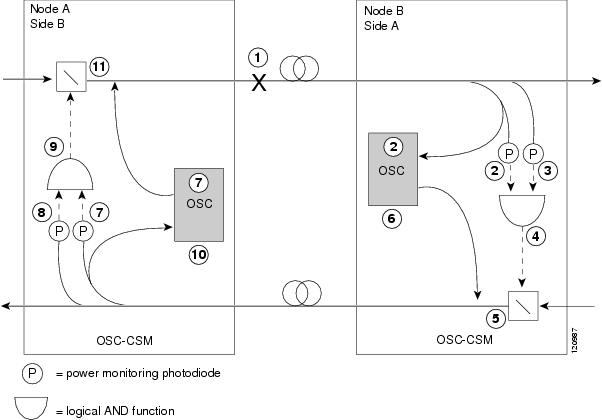
Two photodiodes at the Node B OSC-CSM card monitor the received signal strength for the received optical payload and OSC signals. When the fiber is cut, LOS is detected at both of the photodiodes. The AND function then indicates an overall LOS condition, which causes the Node B OSC laser to shut down and the optical switch to block traffic coming into the node. This in turn leads to LOS for both the optical payload and OSC signals at Node A, which causes Node A to turn off the OSC laser and the optical switch to block incoming traffic. The sequence of events after a fiber cut is as follows (refer to the numbered circles in Figure 16-9):
1. ![]() Fiber is cut
Fiber is cut
2. ![]() Power monitoring photodiode detects a LOS on the OSC and OSC-CSM detects LOS
Power monitoring photodiode detects a LOS on the OSC and OSC-CSM detects LOS
3. ![]() Power monitoring photodiode detects a LOS for the optical payload
Power monitoring photodiode detects a LOS for the optical payload
4. ![]() LOS is declared
LOS is declared
5. ![]() The optical switch blocks incoming traffic
The optical switch blocks incoming traffic
6. ![]() The OSC laser is shut down
The OSC laser is shut down
7. ![]() Power monitoring photodiode detects a LOS on the OSC and OSC-CSM detects LOS
Power monitoring photodiode detects a LOS on the OSC and OSC-CSM detects LOS
8. ![]() Power monitoring photodiode detects a LOS for the optical payload
Power monitoring photodiode detects a LOS for the optical payload
9. ![]() LOS is declared
LOS is declared
10. ![]() The OSC laser is shut down
The OSC laser is shut down
The optical switch blocks incoming traffic
When the fiber is repaired, either an automatic or manual restart at the Node A OSC-CSM OSC or at the Node B OSC-CSM OSC is required. A system that has been shut down is reactivated through the use of a restart pulse. The pulse is used to signal that the optical path has been restored and transmission can begin. For example, when the far end, Node B, receives a pulse, it signals to the Node B OSC to begin transmitting its optical signal and for the optical switch to pass incoming traffic. The OSC-CSM at Node A then receives the signal and tells the Node A OSC to resume transmitting and for the optical switch to pass incoming traffic.
 Feedback