- About this Manual
- Chapter 1, Overview
- Chapter 2, CTC Operations
- Chapter 3, Initial Configuration
- Chapter 4, Configuring Interfaces
- Chapter 5, Configuring Bridging
- Chapter 6, Configuring STP and RSTP
- Chapter 7, Configuring VLANs
- Chapter 8, Configuring 802.1Q and Layer 2 Protocol Tunneling
- Chapter 9, Configuring Link Aggregation
- Chapter 10, Configuring Networking Protocols
- Chapter 11, Configuring IRB
- Chapter 12, Configuring VRF Lite
- Chapter 13, Configuring Quality of Service
- Chapter 14, Configuring the Switching Database Manager
- Chapter 15, Configuring Access Control Lists
- Chapter 16, Configuring Resilient Packet Ring
- Appendix A, Command Reference
- Appendix B, Cisco IOS Commands Not Supported in ML-Series Card Software
- Appendix C, Using Technical Support
Configuring VLANs
This chapter describes VLAN configurations for the ML-Series card. It describes how to configure IEEE 802.1Q VLAN encapsulation. For more information about the Cisco Internet Operating System (IOS) commands used in this chapter, refer to the Cisco IOS Command Reference publication.
This chapter contains the following major sections:
•![]() Configuring IEEE 802.1Q VLAN Encapsulation
Configuring IEEE 802.1Q VLAN Encapsulation
•![]() IEEE 802.1Q VLAN Configuration
IEEE 802.1Q VLAN Configuration
•![]() Monitoring and Verifying VLAN Operation
Monitoring and Verifying VLAN Operation

Note ![]() Configuring VLANs is optional. Complete general interface configurations before proceeding with configuring VLANs as an optional step.
Configuring VLANs is optional. Complete general interface configurations before proceeding with configuring VLANs as an optional step.
Understanding VLANs
VLANs or bridge groups enable network managers to group users logically rather than by physical location. A VLAN is an emulation of a standard LAN that allows secure intra-group data transfer and communication to occur without the traditional restraints placed on the network. It can also be considered a broadcast domain set up within a switch. With VLANs, switches can support more than one subnet (or VLAN) on each switch and give routers and switches the opportunity to support multiple subnets on a single physical link. A group of devices that belong to the same VLAN, but are part of different LAN segments, are configured to communicate as if they were part of the same LAN segment.
VLANs enable efficient traffic separation and provide excellent bandwidth utilization. VLANs also alleviate scaling issues by logically segmenting the physical LAN structure into different subnetworks so that packets are switched only between ports within the same VLAN. This can be very useful for security, broadcast containment, and accounting.
ML-Series software supports port-based VLANs and VLAN trunk ports, which are ports that carry the traffic of multiple VLANs. Each frame transmitted on a trunk link is tagged as belonging to only one VLAN.
ML-Series software supports VLAN frame encapsulation through the IEEE 802.1Q standard on both the ML100T-12 and the ML1000-2. The Cisco ISL VLAN frame encapsulation is not supported. ISL frames will be broadcast at Layer 2, or dropped at Layer 3.
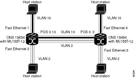
ML-Series switching supports up to 900 VLAN subinterfaces per card (for example, 200 VLANs on 4 interfaces uses 800 VLAN subinterfaces). A maximum of 255 logical VLANs can be bridged per card (limited by the number of bridge-groups). Each VLAN subinterface can be configured for any VLAN ID in the full 1-4095 range. Figure 7-1 shows a network topology in which two VLANs span two ONS 15454s with ML-Series cards.
Figure 7-1 VLANs Spanning Devices in a Network
Configuring IEEE 802.1Q VLAN Encapsulation
On an IEEE 802.1Q trunk port, all transmitted and received frames are tagged except for those on the VLAN configured as the native VLAN for the port. Frames on the native VLAN are always transmitted untagged and are normally received untagged. You can configure VLAN encapsulation on both the ML100T-12 and the ML1000-2.
On an IEEE 802.1Q trunk port, all transmitted and received frames are tagged except for those on the VLAN configured as the native VLAN for the port. On ML-series cards, the native VLAN is always VLAN ID 1. Frames on the native VLAN are normally transmitted untagged and are normally received untagged. Tagging of transmitted native VLAN frames can be forced by the global configuration command vlan dot1q tag native. VLAN encapsulation is supported on both the ML100T-12 and the ML1000-2. VLAN encapsulation is supported for routing and bridging, and is supported on Ethernet interfaces and on POS interfaces with PPP and LEX encapsulation.
To configure VLANs using IEEE 802.1Q VLAN encapsulation, perform the following procedure, beginning in global configuration mode:
|
|
|
|
|---|---|---|
Step 1 |
Router(config)# bridge bridge-group-number protocol type |
Assigns a bridge group (VLAN) number and define the appropriate spanning tree type. See "Configuring Bridging." |
Step 2 |
Router(config)# interface type number
|
Enters interface configuration mode to configure the interface. |
Step 3 |
Router(config-if)#no ip address
|
Disables IP processing. |
Step 4 |
Router(config)# interface type
number.subinterface-number
|
Enters subinterface configuration mode to configure the subinterface. |
Step 5 |
Router(config-subif)# encap dot1q vlan-number |
Sets the encapsulation format on the VLAN to IEEE 802.1Q. |
Step 6 |
Router(config-subif)# bridge-group bridge-group-number |
Assigns a network interface to a bridge group. |
Step 7 |
Router(config-subif)# end |
Returns to privileged EXEC mode. |
Step 8 |
Router# copy running-config startup-config |
(Optional) Saves your configuration changes to NVRAM. |
Note ![]() In a bridge group on the ML-Series card, the VLAN ID does not have to be uniform across interfaces that belong to that bridge group. For example, a bridge-group can connect from a VLAN ID subinterface to a subinterface with a different VLAN ID, and then frames entering with one VLAN ID can be changed to exit with a different VLAN ID. This is know as VLAN translation.
In a bridge group on the ML-Series card, the VLAN ID does not have to be uniform across interfaces that belong to that bridge group. For example, a bridge-group can connect from a VLAN ID subinterface to a subinterface with a different VLAN ID, and then frames entering with one VLAN ID can be changed to exit with a different VLAN ID. This is know as VLAN translation.
Note ![]() IP routing is enabled by default. To enable bridging, enter the no ip routing or bridge IRB command.
IP routing is enabled by default. To enable bridging, enter the no ip routing or bridge IRB command.
Note ![]() Native VLAN frames transmitted on the interface are normally untagged. All untagged frames received on the interface are associated with the native VLAN, which is always VLAN 1. Use the command encapsulation dot1q 1 native.
Native VLAN frames transmitted on the interface are normally untagged. All untagged frames received on the interface are associated with the native VLAN, which is always VLAN 1. Use the command encapsulation dot1q 1 native.
IEEE 802.1Q VLAN Configuration
The VLAN configuration example for the ML100T-12 shown in Figure 7-2 depicts the following:
•![]() Fast Ethernet subinterface 0.1 is in the IEEE 802.1Q native VLAN 1.
Fast Ethernet subinterface 0.1 is in the IEEE 802.1Q native VLAN 1.
•![]() Fast Ethernet subinterface 0.2 is in the IEEE 802.1Q VLAN 2.
Fast Ethernet subinterface 0.2 is in the IEEE 802.1Q VLAN 2.
•![]() Fast Ethernet subinterface 0.3 is in the IEEE 802.1Q VLAN 3.
Fast Ethernet subinterface 0.3 is in the IEEE 802.1Q VLAN 3.
•![]() Fast Ethernet subinterface 0.4 is in the IEEE 802.1Q VLAN 4.
Fast Ethernet subinterface 0.4 is in the IEEE 802.1Q VLAN 4.
Figure 7-2 Bridging IEEE 802.1Q VLANs
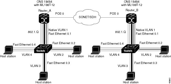
The following shows how to configure VLANs for IEEE 802.1Q VLAN encapsulation. Use this configuration for both router A and router B. The example is shown in Figure 7-2:
Example 7-1 Configure VLANs for IEEE8021Q VLAN Encapsulation
bridge 1 protocol ieee
bridge 2 protocol ieee
bridge 3 protocol ieee
bridge 4 protocol ieee
!
!
interface FastEthernet0
no ip address
!
interface FastEthernet0.1
encapsulation dot1Q 1 native
bridge-group 1
!
interface FastEthernet0.2
encapsulation dot1Q 2
bridge-group 2
!
interface FastEthernet0.3
encapsulation dot1Q 3
bridge-group 3
!
interface FastEthernet0.4
encapsulation dot1Q 4
bridge-group 4
!
interface POS0
no ip address
crc 32
pos flag c2 1
!
interface POS0.1
encapsulation dot1Q 1 native
bridge-group 1
!
interface POS0.2
encapsulation dot1Q 2
bridge-group 2
!
interface POS0.3
encapsulation dot1Q 3
bridge-group 3
!
interface POS0.4
encapsulation dot1Q 4
bridge-group 4
Monitoring and Verifying VLAN Operation
After the VLANs are configured on the ML-Series card, you can monitor their operation by entering the privileged EXEC command show vlans vlan-id. This command displays information on all configured VLANs or on a specific VLAN (by VLAN ID number).

 Feedback