- Overview
- Plan Files and Patch Files
- User Interface
- Plan Objects
- Traffic Demand Modeling
- Simulation
- Simulation Analysis
- Forecasting Traffic
- IGP Simulation
- MPLS Simulation
- RSVP-TE Simulation
- Segment Routing Simulation
- Layer 1 Simulation
- Quality of Service Simulation
- BGP Simulation
- Advanced Routing with External Endpoints
- VPN Simulation
- Multicast Simulation
- Metric Optimization
- RSVP-TE LSP Optimization
- LSP Optimization
- SR-TE Optimization
- SR-TE Bandwidth Optimization
- LSP Disjoint Path Optimization
- LSP Setup Bandwidth Optimization
- LSP Loadshare Optimization
- Capacity Planning Optimization
- Changeover
- Patch Files
- Reports
- Cost Modeling
- Plot Legend for Design Layouts
Cisco WAE Design 6.4 User Guide
Bias-Free Language
The documentation set for this product strives to use bias-free language. For the purposes of this documentation set, bias-free is defined as language that does not imply discrimination based on age, disability, gender, racial identity, ethnic identity, sexual orientation, socioeconomic status, and intersectionality. Exceptions may be present in the documentation due to language that is hardcoded in the user interfaces of the product software, language used based on RFP documentation, or language that is used by a referenced third-party product. Learn more about how Cisco is using Inclusive Language.
- Updated:
- January 19, 2016
Chapter: Advanced Routing with External Endpoints
Advanced Routing with External Endpoints
To model basic IGP routing, demands are sourced or destined for nodes within the topology. To model basic inter-AS routing, the sources and destinations are neighboring external AS’s, or a combination of the external AS and the peering node in that AS. However, more complex routing situations require the use of external endpoints as the source or destination. External endpoints can contain multiple member nodes and AS's, and you can specify when traffic enters or exits from each of them individually. This allows you to simulate routing within and between AS’s where multiple traffic entry and exit points are used simultaneously. You can also prioritize where the traffic fails over to other nodes and AS’s.
There are numerous use cases both for IGP and inter-AS routing.
- Simulate content caching failovers for in-network source of demands that are backed up by another in-network source. If connectivity is lost to the first, the traffic is then sourced from the second.
- Simulate edge routing with a single entry point into the network edge and a specific failover point. Alternatively, you could model multiple entry points, depending on which is closest to the destination.
- Simulate complex BGP routing policies from a transit provider. For example, a transit entry location and failover location can be specified per destination.
- Simulate failover between peering AS's, for example from one single-connection transit provider to another.
|
|
|
|---|---|
Traffic Demand Modeling chapter |
|
BGP Simulation chapter |
Routing with External Endpoints
An external endpoint is a WAE Design object that identifies specific entry (source) or exit (destination) points for demands. These are identified in the External Endpoints table by a name and an optional Tag property.
Each external endpoint consists of one or more members that are defined as nodes, external AS’s, or a combination of an external AS and external node. As such, by setting a demand’s source or destination to an external endpoint, you can simulate traffic going from multiple sources to a single destination, from a single source to multiple destinations, or multiple sources going to multiple destinations. Because of this flexibility, they are useful for specifying particular secondary entry and exit points in the event of failures.
External Endpoint Members
Each member is assigned properties that prioritize traffic entering and exiting that member, in what order to failover to another member, and how to distribute traffic for members of equal priority. These properties are set when you create the member (in its Properties dialog box), and all members are listed in the External Endpoint Members table.
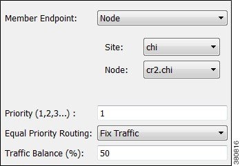
- Member Endpoint—Defines whether the member is a node, AS, or external node via an AS.
- Priority—The sequential order in which external endpoint members are used in the simulations should failures occur.
- Equal priority routing—If members have the same priority, this property identifies how the traffic is distributed.

Note![]() Members within an external endpoint that have the same priority must either all be Shortest Path or none of them be Shortest Path.
Members within an external endpoint that have the same priority must either all be Shortest Path or none of them be Shortest Path.
–![]() Shortest Path—Use the member that results in the use of shortest path between source and destination.
Shortest Path—Use the member that results in the use of shortest path between source and destination.
If a member is using a shortest path, an “na” shows in the Traffic Balance (%) column in the External Endpoint Members table.
–![]() Fix Traffic—Set the traffic across members of equal priority as defined in the Traffic Balance (%) field.
Fix Traffic—Set the traffic across members of equal priority as defined in the Traffic Balance (%) field.
–![]() Deduce Traffic—Behaves the same as Fix Traffic in that it sets traffic across members of equal priority as defined in the Traffic Balance (%) field. However, upon running Demand Deduction, the Traffic Balance (%) field is updated based on the measured traffic in the network. Note that Demand Deduction only estimates the traffic balances for external endpoints with a priority that is in use in the current no-failure simulation. Thus, Deduce Traffic is usually set to Priority 1.
Deduce Traffic—Behaves the same as Fix Traffic in that it sets traffic across members of equal priority as defined in the Traffic Balance (%) field. However, upon running Demand Deduction, the Traffic Balance (%) field is updated based on the measured traffic in the network. Note that Demand Deduction only estimates the traffic balances for external endpoints with a priority that is in use in the current no-failure simulation. Thus, Deduce Traffic is usually set to Priority 1.
Routing Simulations

Note![]() Although this section describes demands as being sourced from an external endpoint, the same methodology holds true if a demand’s destination is an external endpoint.
Although this section describes demands as being sourced from an external endpoint, the same methodology holds true if a demand’s destination is an external endpoint.
If a demand’s source is defined as an external endpoint, then the following selection of external endpoint members ensues.

Step 1![]() Members with the highest priority (lowest number) are used as the demand’s source. For example, if the external endpoint has two members with a priority of 1, the demand is sourced from both members provided they are available.
Members with the highest priority (lowest number) are used as the demand’s source. For example, if the external endpoint has two members with a priority of 1, the demand is sourced from both members provided they are available.
If one or more of the members are not available, the traffic from the unavailable members is evenly redistributed to the other top priority members.
Step 2![]() If none of the top priority members are available to source the traffic but there are next-priority members available, step 1 is repeated for the next priority external endpoint members. Only if all members with the same priority fail does the traffic get routed according to the next priority in the sequence.
If none of the top priority members are available to source the traffic but there are next-priority members available, step 1 is repeated for the next priority external endpoint members. Only if all members with the same priority fail does the traffic get routed according to the next priority in the sequence.
Note that if a failure occurs that does not affect the external endpoint member’s ability to send or receive traffic, then traffic is rerouted as usual without a need to use the additional members.
If an external endpoint member is an external AS, with or without a node specified, then the routing from or to that member is determined by the BGP routing policy determined by the AS relationships. The distribution of traffic between external endpoints with the same priority is the same as for node members. For more information about AS routing, see the BGP Simulation chapter.

Traffic Distribution
The traffic distribution through these demands is based on the Equal Priority Routing property, and if applicable, the Traffic Balance (%) property used to define the external endpoint members.

- If there is only one member and it is defined as Shortest Path, the demand takes the shortest path as defined by the IGP metrics.
Of the routable demands, if the Traffic Balance (%) values are all empty, the traffic is routed and equally load balanced across the demands with the shortest IGP paths. Note in the case of multiple internal AS's, the shortest IGP route is the shortest route in the first AS the demand enters.
- If multiple members of the same priority are set to Shortest Path, the demand takes the path with the shortest IGP path. If all interfaces between the source members and the destination have the same shortest IGP paths, then the traffic is load balanced equally across them.
- If one or more members of the same priority have their Equal Priority Routing property set to Fix Traffic or Deduce Traffic, the demand traffic is split according to each member’s Traffic Balance (%) value.

–![]() If the Traffic Balance percentages across sources with the same priority sum to less than 100%, the overall demand traffic is decreased to that percentage.
If the Traffic Balance percentages across sources with the same priority sum to less than 100%, the overall demand traffic is decreased to that percentage.
–![]() If an external endpoint member of the same priority fails, the traffic on the remaining members increases in proportion, so that the same amount of traffic is still routed.
If an external endpoint member of the same priority fails, the traffic on the remaining members increases in proportion, so that the same amount of traffic is still routed.
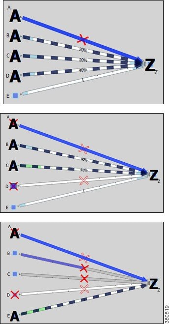
Example: Node A is failed. Nodes B, C, and D each have a priority of 2 and are each a Fix Traffic type. Their traffic balances are 20%, 20%, and 40%, respectively. The demand has 1,000 Mbps of traffic.

–![]() Since Node A failed, the demand routes 200 Mbps traffic through node B, 200 Mbps through C, and 400 Mbps through D, totaling 800 Mbps (Figure 16-1).
Since Node A failed, the demand routes 200 Mbps traffic through node B, 200 Mbps through C, and 400 Mbps through D, totaling 800 Mbps (Figure 16-1).
–![]() If Node D fails, then the demand routes 400 Mbps traffic through Node B and 400 through C. If Node B fails too, the entire 800 Mbps is routed through C (Figure 16-1).
If Node D fails, then the demand routes 400 Mbps traffic through Node B and 400 through C. If Node B fails too, the entire 800 Mbps is routed through C (Figure 16-1).
–![]() If all three priority 2 members fail, then 1000 Mbps is routed through node E, which is the priority 3 member (Figure 16-1).
If all three priority 2 members fail, then 1000 Mbps is routed through node E, which is the priority 3 member (Figure 16-1).
Figure 16-1 Example Effect of Failures When Using External Endpoints
States
External endpoint members can be failed, set to an inactive state, and included in Simulation Analysis to calculate a worst-case failure analysis. Additionally, they can be included in SRLGs, which in turn can also be failed, set to inactive, and included in Simulation Analysis. Table 16-1 shows the icons used for these states.
If the external endpoint member that you fail or set to inactive is an AS, then entry through any of its nodes is not possible. The same is true if an SRLG is failed or set to inactive and if it contains an external endpoint member that is an AS.
In-Network Routing Examples
Content from Multiple Data Centers
This example demonstrates servers that cache content for customers in Kansas City (cr1.kcy). The primary server is located in San Jose (cr1.sjc), with backup servers in Mountain View (cr1.mtv) and Palo Alto (cr1.paa). Each of the servers is a member of an external endpoint (sjc_server) that is used as the source of the demand to cr1.kcy.
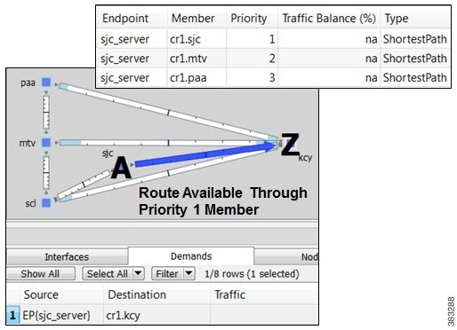
- Member cr1.sjc has a priority of 1, and it takes the shortest path.
- Member cr1.mtv has a priority of 2, and it takes the shortest path.
- Member cr1.paa has a priority of 3, and it takes the shortest path.
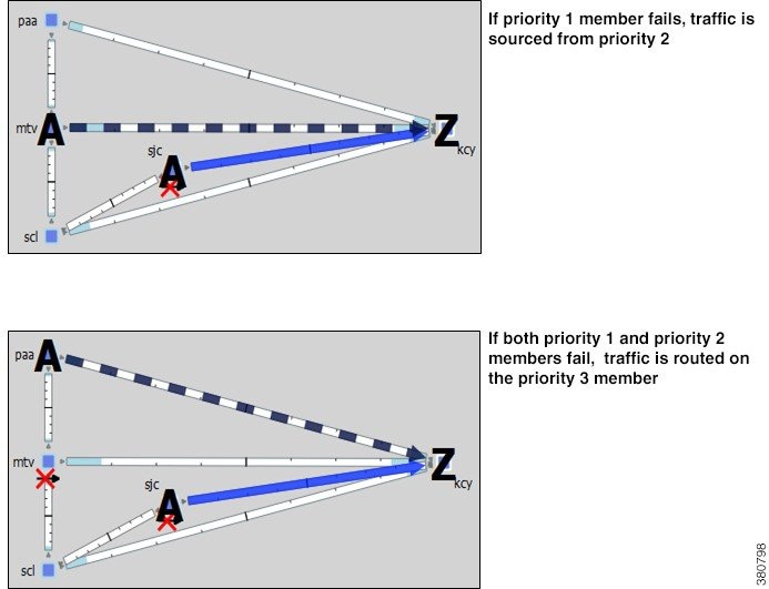
Figure 16-2 shows how the failure scenario works.
- When the priority 1 server node fails (cr1.sjc), content continues to be delivered using cr1.mtv as the source.
- If cr1.mtv were also to fail, then cr1.paa would source the traffic to cr1.kcy.
Figure 16-2 Example Failover for Multiple Data Centers
External Source
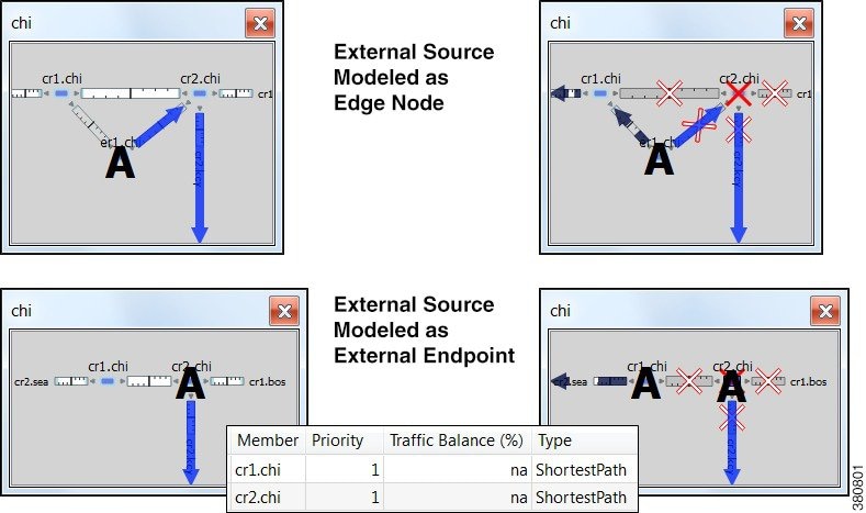
One method of modeling an external demand source with multiple entry points is to construct an edge node, connecting it to these entry points, and giving the interfaces equal metrics. Then source the demand from this edge node.
Alternatively, you can construct these multiple entry points using a single external endpoint as the demand source, thus reducing the complexity of the topology.
In this example, a demand has an external source with two entry points that come into the network at Chicago. Figure 16-3 demonstrates two ways to model this source. One uses additional topology (edge node) to source the demand. The other uses a single external endpoint that has two members (cr1.chi and cr2.chi), both set to priority 1 with shortest path traffic.
Figure 16-3 Example External Demand Source
Intra-AS Routing Examples
Failover to Nodes in External AS’s
This example demonstrates a content provider (Acme) who has most of its incoming Internet traffic sourced through a transit provider, and this traffic is then distributed to Acme’s customers. Acme has identified specific policies for each market using communities, and these policies determine, per location, which transit provider peering points are used for primary routing and failover. The network is set up as follows (Figure 16-4).
- The San Diego, Boise, Cheyenne, and Seattle nodes each belong to the same transit provider, AS 2.
- The remaining nodes belong to Acme’s internal AS (AS 1), and these are Acme’s customers.
- The San Diego node (pr1.sdg) in AS 2 is sending traffic to three key customers located in Phoenix (cr1.pho), Salt Lake City (cr1.slc), and Denver (cr1.dnv).
Figure 16-4 Example Transit Peer AS 2 San Diego Sends Traffic to Customers in an Internal AS
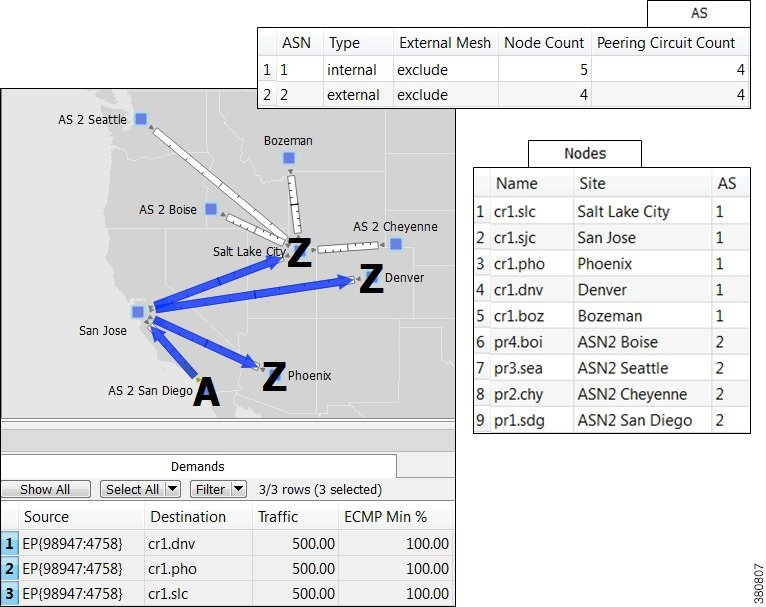
In WAE Design, Acme uses an external endpoint named after community 98947:4758. It contains the following members, all of which are in the same AS 2 transit provider.
- pr1.sdg set to priority 1 with shortest path traffic
- pr2.chy set to priority 2 with shortest path traffic
- AS 2, which means the remaining nodes in the AS, set to priority 3 with shortest path traffic
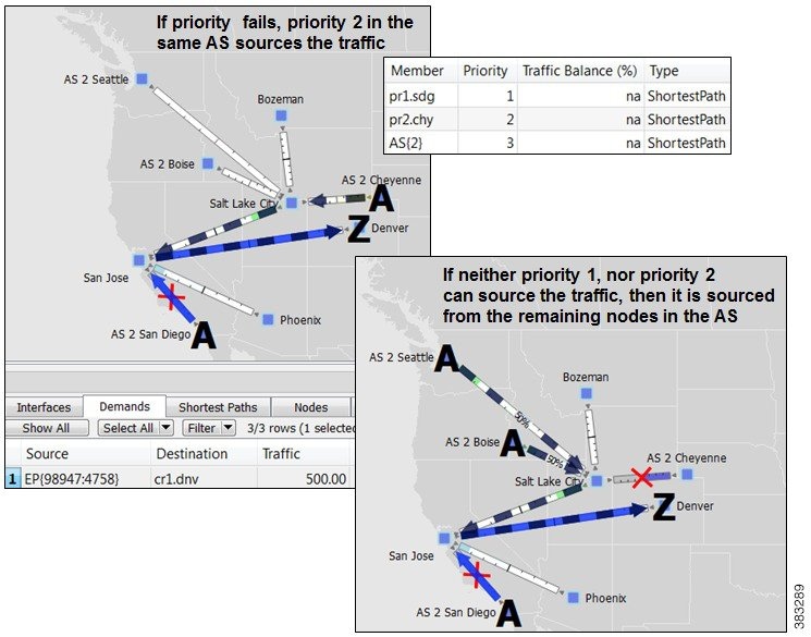
As Figure 16-4 shows, multiple demands are created using this external endpoint (98947:4758) as the source, and each sending traffic to a different customer destination. Figure 16-5 focuses on the traffic destined for Denver (cr1.dnv), showing that the failover scenario behaves as follows.
- If a failure prevents the peer pr1.sdg node from sending traffic to cr1.pho, a failover occurs to pr2.chy within that same peer so that there is no service disruption.
- If failures occur such that neither pr1.sdc, nor pr2.chy can send traffic to cr1.dnv, the remaining nodes in the AS source the traffic. Although this is set to use the shortest path, since there are multiple paths, the traffic is distributed evenly.
Note, the same result could have been achieved by setting the priority 1 to an interface going from San Jose to pr1.sdg and by setting the priority 2 to an interface going from Salt Lake City to pr2.chy.
Figure 16-5 Example Failover Within the Same External AS
Failover from an External AS to Another
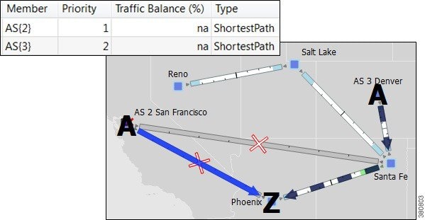
In this example, a small ISP (AcmeNet) buys transit from two other service providers. AcmeNet peers with AS 2 in Phoenix and AS 3 in Denver. AcmeNet has a customer base in Phoenix (cr1.pho). The customer has a preferred access to the Internet through the San Francisco (pr1.sfo) in AS 2 (Figure 16-6), and the secondary access is through Denver (pr2.dnv) in AS 3 (Figure 16-7). In WAE Design, AcmeNet simulates this network by creating an external endpoint (Internet) containing two different external AS’s as members.
The demand is sourced from this external endpoint named Internet.
Figure 16-6 Example Transit Peer ASN2 San Francisco Sends Traffic to Customers in an Internal AS
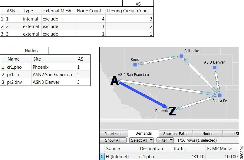
Figure 16-7 Example Failover to a Different External AS
Create External Endpoints and Their Members
The easiest and recommended method of creating external endpoint members is to do so while creating its associated external endpoint, as follows.
Step 1![]() Either right-click in an empty area and select New->Demands->External Endpoints, or select the Insert->Demands->External Endpoints menu. An external endpoint Properties dialog box opens.
Either right-click in an empty area and select New->Demands->External Endpoints, or select the Insert->Demands->External Endpoints menu. An external endpoint Properties dialog box opens.
To edit existing external endpoints, double-click it from the External Endpoints table.

Step 2![]() Enter a unique external endpoint name in the Name field.
Enter a unique external endpoint name in the Name field.
Step 3![]() To add a new member, click the New button.
To add a new member, click the New button.
To edit an existing member, select it from the Members table and click Edit.
An external endpoint member Properties dialog box appears.
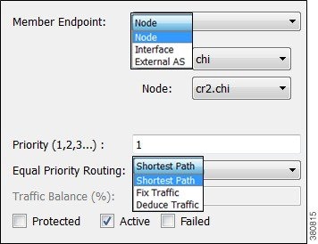
a.![]() Select the member type as node or external AS.
Select the member type as node or external AS.
–![]() For nodes, select its site and node name.
For nodes, select its site and node name.
–![]() For interfaces, select its site, node, and the interface. Using an interface enables you to specify the exact interface on which the demand traffic is going into or out of a node.
For interfaces, select its site, node, and the interface. Using an interface enables you to specify the exact interface on which the demand traffic is going into or out of a node.
–![]() For AS’s, select its AS name, and select either the “unspecified” option or node name within the AS. The “unspecified” option routes traffic evenly throughout the entire AS.
For AS’s, select its AS name, and select either the “unspecified” option or node name within the AS. The “unspecified” option routes traffic evenly throughout the entire AS.

Note![]() For information on how the following external endpoint member fields affect routing, see the Routing with External Endpoints section.
For information on how the following external endpoint member fields affect routing, see the Routing with External Endpoints section.
b.![]() Enter a priority number to determine the sequence in which the member is used with other members in this external endpoint. Multiple members can have the same priority.
Enter a priority number to determine the sequence in which the member is used with other members in this external endpoint. Multiple members can have the same priority.
c.![]() Select whether to use a shortest path route, or to direct a specified percentage of traffic across members that have the same priority (Fix Traffic or Deduce Traffic).
Select whether to use a shortest path route, or to direct a specified percentage of traffic across members that have the same priority (Fix Traffic or Deduce Traffic).
d.![]() If balancing traffic, enter the percentage of traffic this member should route.
If balancing traffic, enter the percentage of traffic this member should route.
If you set Deduce Traffic, this value is updated by Demand Deduction provided there are no members with a higher priority that are in use under normal (non-failure) operation.
e.![]() Click OK in the external endpoint member Properties dialog box.
Click OK in the external endpoint member Properties dialog box.
Step 4![]() Click OK in the external endpoint Properties dialog box.
Click OK in the external endpoint Properties dialog box.
Related Topics
- BGP Simulation chapter
- Traffic Demand Modeling chapter
- Simulation chapter


 Feedback