- Overview
- Plan Files and Patch Files
- User Interface
- Plan Objects
- Traffic Demand Modeling
- Simulation
- Simulation Analysis
- Forecasting Traffic
- IGP Simulation
- MPLS Simulation
- RSVP-TE Simulation
- Segment Routing Simulation
- Layer 1 Simulation
- Quality of Service Simulation
- BGP Simulation
- Advanced Routing with External Endpoints
- VPN Simulation
- Multicast Simulation
- Metric Optimization
- RSVP-TE LSP Optimization
- LSP Optimization
- SR-TE Optimization
- SR-TE Bandwidth Optimization
- LSP Disjoint Path Optimization
- LSP Setup Bandwidth Optimization
- LSP Loadshare Optimization
- Capacity Planning Optimization
- Changeover
- Patch Files
- Reports
- Cost Modeling
- Plot Legend for Design Layouts
Cisco WAE Design 6.4 User Guide
Bias-Free Language
The documentation set for this product strives to use bias-free language. For the purposes of this documentation set, bias-free is defined as language that does not imply discrimination based on age, disability, gender, racial identity, ethnic identity, sexual orientation, socioeconomic status, and intersectionality. Exceptions may be present in the documentation due to language that is hardcoded in the user interfaces of the product software, language used based on RFP documentation, or language that is used by a referenced third-party product. Learn more about how Cisco is using Inclusive Language.
- Updated:
- January 19, 2016
Chapter: MPLS Simulation
MPLS Simulation
This chapter describes how WAE Design simulates MPLS routing. All LSPs other than SR (segment routed) LSPs are routed like RSVP LSPs. For MPLS simulation information specific to these types of LSPs, refer to RSVP-TE Simulation and Segment Routing Simulation chapters.
- LSPs are established under normal operation: that is, with failures not taken into account.
- Any LSPs that are affected by the failures are rerouted. Depending on the LSP path settings, reroutes might involve moving to a secondary path, dynamically rerouting the LSPs, or rerouting based on a segment list.
- Demands are routed using the established LSPs using the specified IGP protocols given the specified failure scenarios.
- LSP utilizations are calculated from the demand traffic using the specified traffic level.
LSP Types
- SR LSPs —Segment routing LSPs, which do not use RSVP for routing. You can create SR LSPs using the WAE Design GUI. They are identified with a Type property of SR. For more information, see the Segment Routing Simulation chapter.
- RSVP LSPs —LSPs that are established through RSVP. These are commonly known as MPLS TE tunnels. WAE Collector discovers RSVP LSPs, and you can also create them using the WAE Design GUI. They are identified with a Type property of RSVP. For more information, see the RSVP-TE Simulation chapter.
WAE Design does not distinguish between LDP and RSVP LSPs.

Note![]() PCEP LSPs can be either an SR or RSVP LSP, and are identified with a PCEP property of T (true).
PCEP LSPs can be either an SR or RSVP LSP, and are identified with a PCEP property of T (true).
Creating and Visualizing LSPs and LSP Paths
To simulate MPLS LSPs in the network, you must first set up the LSPs to be routed. In the WAE Design GUI, enter LSPs into the plan file in the following ways.
- By selecting the Insert->LSPs->LSP menu, or by right-clicking in the plot and then selecting the New->LSPs->LSP from the context menu. This opens a dialog box for entering properties for a single LSP. One such property is the Type, which determines whether this is an RSVP LSP or an SR LSP.
- By selecting the Insert->LSPs->LSP Mesh menu or by double-clicking in the plot and then selecting the New->LSPs->LSP Mesh menu. This opens a dialog box for adding a mesh of LSPs between the selected nodes. Again, the Type property determines whether the LSP is an RSVP or an SR LSP.
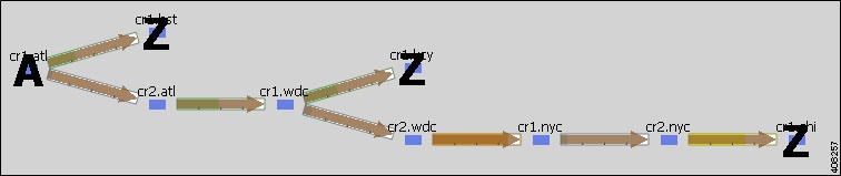
When selected, LSPs appear in the plot as a brown arrow. To view the details of LSP routes, as shown in Figure 10-1, follow these steps.
Step 1![]() Select one or more LSPs from the LSPs table.
Select one or more LSPs from the LSPs table.
Step 2![]() Right-click and select Plot LSPs from the context menu.
Right-click and select Plot LSPs from the context menu.
To move the plot horizontally or vertically, use the left/right arrows and up/down arrows, respectively.
To select all LSPs within the LSP plot view, click the Select LSPs button. To deselect all of these LSPs, click in an empty plot area.
Note that you can plot one or more LSP paths in the same manner by selecting them from the LSP Paths table.
To filter to related information, such as related interfaces, source and destination nodes, or demands, right-click one or more LSPs and select the option from the context menu.
Figure 10-1 LSP Plot View of Three LSPs with the Same Source
LSP Paths
LSPs can be assigned one or more LSP paths. Like LSPs, LSP paths have properties that vary depending on whether the path is for an RSVP LSP or SR LSP. If these properties are omitted, then they are inherited from the LSP. If these properties are set in the LSP path, they override the LSP settings. For information on these properties, see the RSVP-TE Simulation and Segment Routing Simulation chapters.
Once an LSP path is created, you can use an initializer to create explicitly routed paths. For information, see the Create LSP Paths and Explicit LSP Paths Initializer sections.
Path Options and Active Path
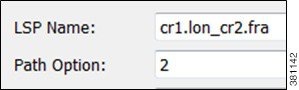
Each LSP path is specified Path Option property. In this case, the LSP is routed using the first LSP path that can successfully be established. LSP paths are established in increasing order of their path option, where path option 1 is established first.
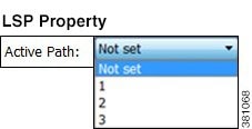
Alternatively, you can select which LSP path to use from the LSP Active Path drop-down list in the LSP Property dialog box.
Create LSP Paths
Step 1![]() In the LSPs table, select the LSP to which you are adding LSP paths.
In the LSPs table, select the LSP to which you are adding LSP paths.
Step 2![]() Either right-click in the plot and select New->LSP Paths or select the Insert->New LSP Paths menu. The Insert LSP Paths dialog box appears.
Either right-click in the plot and select New->LSP Paths or select the Insert->New LSP Paths menu. The Insert LSP Paths dialog box appears.
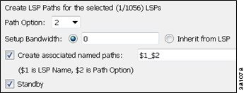
Step 3![]() In the Path Option field, enter the order in which the LSP path is activated. Lower numbers have preference over higher numbers.
In the Path Option field, enter the order in which the LSP path is activated. Lower numbers have preference over higher numbers.
Step 4![]() If this is an RSVP LSP path, optionally set these properties. For information on these properties, see the RSVP-TE Simulation chapter.
If this is an RSVP LSP path, optionally set these properties. For information on these properties, see the RSVP-TE Simulation chapter.
a.![]() If this is a standby LSP path, click Standby, which ensures the paths are always active.
If this is a standby LSP path, click Standby, which ensures the paths are always active.
b.![]() To set the bandwidth, specify the Setup Bandwidth for the LSP path, or select that it should inherit the bandwidth from the LSP.
To set the bandwidth, specify the Setup Bandwidth for the LSP path, or select that it should inherit the bandwidth from the LSP.
c.![]() To create associated named paths, click this option and complete the name using $1 for the LSP name and $2 for the path option.
To create associated named paths, click this option and complete the name using $1 for the LSP name and $2 for the path option.
d.![]() To associate the LSP path with affinities, click Edit in the Affinities section. For example, you might want to associate a standby path with an affinity that forces it on a different path than the primary path. LSP paths can inherit the affinity from the LSP or can be assigned a specific affinity.
To associate the LSP path with affinities, click Edit in the Affinities section. For example, you might want to associate a standby path with an affinity that forces it on a different path than the primary path. LSP paths can inherit the affinity from the LSP or can be assigned a specific affinity.
Visualize LSP Shortest Paths
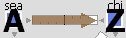
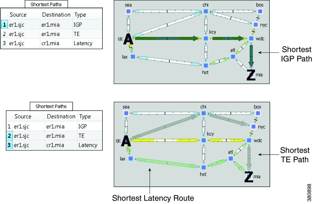
To view the LSP shortest paths, use one of these methods. The source is marked with an “A” and the destination is marked with a “Z”.
- Using the View->LSPs sub-menus, you can choose to see the shortest actual paths, shortest latency paths, or shortest TE paths each time that you select an LSP.
- To view all shortest IGP paths, shortest TE paths, and/or shortest latency paths for selected LSPs, use the context menu. Select one or more LSPs, right-click, and select Filter To->Shortest Paths (Figure 10-2).
Figure 10-2 LSP Shortest IGP, Shortest TE, and Shortest Latency Paths
Path Latency Calculations
WAE Design calculates shortest latency paths for LSPs and demands as follows.
- By default, WAE Design uses the shortest path from the source to the destination of the LSP or demand, where the weight on each interface is the delay value for that interface.
- If the delay for any interface is zero (as it is by default), a small (0.00001 ms) delay is used instead. This means that if all the delays for the interfaces in the plan are zero, the path with the smallest number of hops is selected.
- In cases where two different paths have the same latency, paths with the smaller number of hops are preferred.
Explicit LSP Paths Initializer
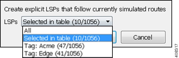
The Explicit LSP Paths Initializer automates the process of explicitly routing existing LSP paths to follow their currently simulated routes.
- For RSVP LSPs, the initializer converts a set of dynamically routed LSPs to explicitly routed LSPs along their current paths.
The initializer creates named paths and named path hops for both primary and secondary paths. The explicit paths are named <LSP Name>_<Path Option>. Orphaned named paths are deleted. (Named paths are orphans if they are no longer used by any of the LSP paths.) For more information on RSVP LSPs, see the RSVP-TE Simulation chapter.
- For SR LSPs, the only use case is if you want the initializer to create a final segment list hop on the destination node. For more information on SR LSPs, see the Segment Routing Simulation chapter.
WAE Design writes a report identifying the number of selected LSP paths. To access this information later, select the Window->Reports menu.
Step 1![]() Select the Initializers->Explicit LSP Paths menu, or right-click a selected LSP and select Explicit LSP Paths Initializer from the context menu.
Select the Initializers->Explicit LSP Paths menu, or right-click a selected LSP and select Explicit LSP Paths Initializer from the context menu.
Step 2![]() Select whether to create explicit paths for all LSPs, selected LSPs, or tagged LSPs, and then click OK.
Select whether to create explicit paths for all LSPs, selected LSPs, or tagged LSPs, and then click OK.
Routing Demands
Intra-Area LSPs
Intra-area LSPs are modeled as IGP shortcuts. That is, the source of the demand using the LSP can be a node other than the ingress node into the IGP, and the destination node of the LSP can be a node other than the egress node from the IGP. A demand through intra-area LSPs does not require the LSP to traverse the full demand path.
Each intra-area LSP has a metric that helps determine which traffic is routed through the LSP. By default, autoroute LSPs have a metric equal to the shortest IGP distance from the source to the destination. However, you can configure static metrics for these LSPs that override this default. Static metrics can also be defined relative the shortest IGP distance, but these relative metrics are not currently supported in WAE Design.
Forwarding adjacency LSPs always have a metric. If not specified, the default is 10. Forwarding adjacency LSP metrics are injected into the IGP so that nodes other than the source node of the LSP are aware of the path length through the forwarding adjacency LSP, and use it in their shortest path calculations.
To edit autoroute and forwarding adjacencies, select one or more LSPs from the LSP table; double-click to bring up the Properties dialog box and edit the values in the Routing area.
Inter-Area LSPs
Since it is not possible to define metrics distances across ISP areas, there can be no well-defined metric for inter-area LSPs. Therefore, in WAE Design, a demand only routes through an inter-area LSP if the demand’s endpoints are nodes matching the source and destination of the LSP, interfaces on these nodes, or external AS's whose ingress and egress points through the IGP are these nodes. This requirement is true regardless of the network option settings.
To be routed, these demands must also match the privacy, tags, and class-based forwarding requirements. Autoroute, forwarding adjacency properties, and LSP metrics are ignored. For information on privacy, see the Private LSPs section, for information on tags, see the Plan Objects chapter, and for information on class-based forwarding, see the Class-Based Forwarding section.
Loadsharing
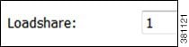
Two or more LSPs with the same source and destination (and metrics, if these are defined) loadshare traffic between them. How the load is shared between the LSPs is determined by the LSP Loadshare property. By default, LSPs have a Loadshare property of 1, and thus route traffic between them in equal proportions. Changing the Loadshare value changes the distribution of LSP traffic and interface traffic in proportion to these values.
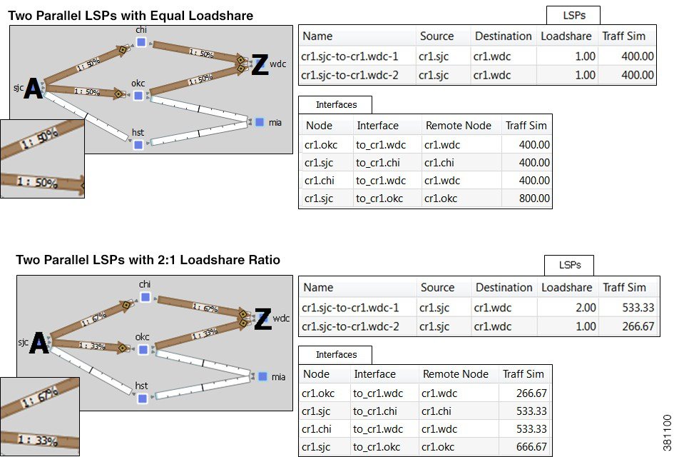
Example: If two LSPs are parallel, and one has a Loadshare property of 2 and one has a Loadshare property of 1, there will be a 2-to-1 ratio of traffic shared between them. The top half of Figure 10-3 shows an example of two parallel LSPs that are routed using strict explicit paths. Each has a Loadshare value of 1, which means the traffic is routed using a 1:1 loadshare ratio so that each LSP carries 50% of the traffic. In contrast, the lower half shows the same parallel LSPs with a 2:1 ratio. That is, one LSP has a Loadshare value of 2, and one has a Loadshare property value of 1. The LSP with a Loadshare value of 2 carries 67% of the traffic, while the other carries 33%.
Each LSP has a path showing the percentage of traffic that crosses the LSP as a result of the Loadshare value for that LSP. The format is <path option>:<loadshare percentage>%. Although loadshare applies only to path option 1, the LSP itself might be routed along a different path.
Note that this percentage may or may not be the same as the Loadshare value in the LSPs table. This is because the Loadshare value is relative to the other Loadshare values for parallel LSPs. For this reason, if manually editing the Loadshare property, it is recommended that you consider the entire set of parallel LSPs. Note also that since an LSP can be in multiple sets of parallel LSPs, the percentage on its path can differ.
To optimize these Loadshare values, use the LSP Loadshare Optimization tool. For information, see the LSP Loadshare Optimization chapter.
Figure 10-3 Example of Two Parallel LSPs with Equal Loadsharing
Class-Based Forwarding
Class-based forwarding (CBF) enables you to manage differentiated service requirements by restricting or allowing demands into LSPs according to a set of user-defined mappings between demand service classes and LSPs. For instance, a demand with an Assured Forwarding service class could be mapped to an LSP saved for carrying low-latency voice traffic, while a different LSP using that same demand could be used for only best-effort services, such as file transfers.
Class-Based Forwarding Simulations
Demands can be assigned a Service Class property. LSPs can be assigned a Class property. CBF is enabled by creating a table that maps the demand service class to the LSP classes. The resulting table defines a set of LSPs to which a demand with a specific service class has access.
Figure 10-4 Example Service Class LSP Class Mapping Table
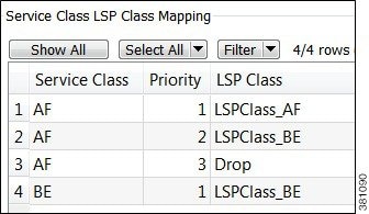
- Each demand service class in the table is mapped to one or more LSP classes, or with a Drop value.
- If a demand’s service class is in the mapping table, the demand can only use LSPs with LSP classes that match that service class.
If a demand service class is not in the mapping table, it can use any LSP.
Example: There are three demand service classes: AF, BE, and EX. The mapping table contains only AF and BE (Figure 10-4). This means that the demands with EX service class can use any LSP in the plan file.
- If an LSP class does not appear in this mapping table, then any demand can use any LSP of that class.
- If multiple LSPs are sourced from one node, demands routed through that node can use any LSP to which the demand’s service class is mapped.
–![]() If all available LSPs have LSP classes with equal priority, the traffic is load balanced between these LSPs.
If all available LSPs have LSP classes with equal priority, the traffic is load balanced between these LSPs.
–![]() If the LSPs have prioritized LSP classes (1, 2, 3, etc.), those with the highest priority (lowest number) are routed first.
If the LSPs have prioritized LSP classes (1, 2, 3, etc.), those with the highest priority (lowest number) are routed first.
Example: A demand with an AF service class must first use LSPs with an LSPClass_AF because within the AF service class, this is the only Priority 1 LSP class. If no LSPs with LSPClass_AF are available, the demand will attempt to route across LSPs with an LSPClass_BE class (Figure 10-4).
–![]() If the demand’s service class is not mapped to a Drop value, the demand forgoes using LSPs and takes the shortest IGP path.
If the demand’s service class is not mapped to a Drop value, the demand forgoes using LSPs and takes the shortest IGP path.
–![]() If the demand’s service class is mapped to a Drop value, the demand is unrouted.
If the demand’s service class is mapped to a Drop value, the demand is unrouted.
Example: If there are no available LSPs for the AF demand to route across, it will not route due to the Drop value associated with it (Figure 10-4). If the BE demand cannot route across an LSP that has a class of LSPClass_BE, it will route across the shortest IGP path available.
Example Simulations
In these examples, we want to route the assured-forwarding (AF) Europe-to-Japan traffic directly over the more expensive, but lower latency, circuits through Russia. We want to route the best-effort (BE) traffic along the cheaper, but higher latency, circuits through the US.
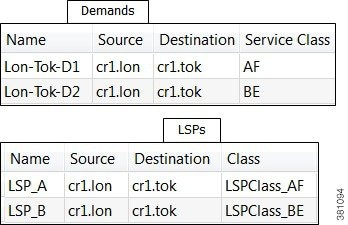
In these example simulations, there are only two demands and two LSPs. Both demands and both LSPs go from London to Tokyo.
- Lon-Tok-D1 demand uses an AF service class.
- Lon-Tok-D2 demand uses an BE service class.
- The LSPs are named LSP_A and LSP_B. Each LSP is explicitly routed to reach Tokyo via a different path.
–![]() LSP_A is assigned to LSPClass_AF.
LSP_A is assigned to LSPClass_AF.
–![]() LSP_B is assigned to LSPClass_BE.
LSP_B is assigned to LSPClass_BE.
Figure 10-5 shows a simple one-to-one mapping between a service class and an LSP class.
- The AF service class is mapped to LSPClass_AF.
- The BE service class is mapped to LSPClass_BE.
- If the circuit between London and Tokyo fails, the Lon-Tok-D1 demand reroutes using the shortest IGP path. The reason is because there are no alternative LSPs available.
Figure 10-5 Example Reroute Around Failure Using IGP Path
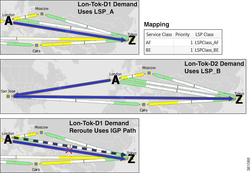
Figure 10-6 shows that the AF service class is mapped to both LSPClass_AF and LSPClass_BE. The Lon-Tok-D1 demand now reroutes around a failure between London and Tokyo by using LSP_B. This is because the AF service class now has a Priority 2 mapping to the LSPClass_BE class, and the fact that LSP_B is assigned to this LSPClass_BE class.
Figure 10-6 Example Reroute Around Failure Using Alternative LSP Class
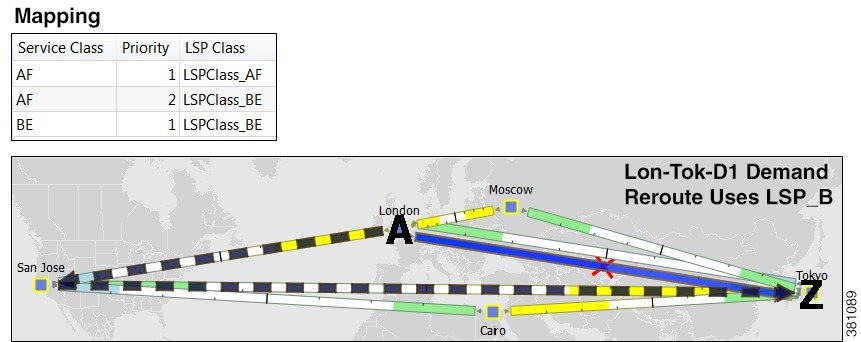
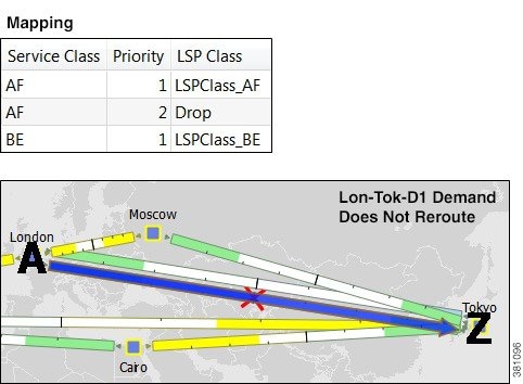
Figure 10-7 shows that the AF service class is mapped to both LSPClass_AF and a Drop value. The Lon-Tok-D1 demand now does not reroute around a failure between London and Tokyo. This is because demands using AF service class are mapped such that if an LSP with an LSPClass_AF class is not available, then the traffic is dropped.
Figure 10-7 Example of Not Rerouting Based on Drop LSP Class
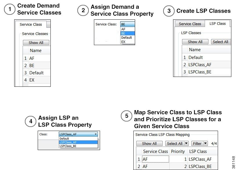
Workflow for Creating Service Class and LSP Class Mappings
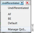
The workflow for creating mappings between service classes and LSP classes is as follows (Figure 10-8).
Step 1![]() Create the service classes using the Manage QoS dialog box. For information, see the Quality of Service Simulation chapter.
Create the service classes using the Manage QoS dialog box. For information, see the Quality of Service Simulation chapter.
Step 2![]() Assign demands to the service classes. To assign this property, use the Service Class menu in the demand’s Properties dialog box. (Right-click one or more selected demands, and select Properties.)
Assign demands to the service classes. To assign this property, use the Service Class menu in the demand’s Properties dialog box. (Right-click one or more selected demands, and select Properties.)
Step 3![]() Create the LSP classes using the Manage QoS dialog box. For information, see the Create LSP Classes section.
Create the LSP classes using the Manage QoS dialog box. For information, see the Create LSP Classes section.
Step 4![]() Assign LSPs to the LSP classes. For information, see the Assign LSP Classes to LSPs section.
Assign LSPs to the LSP classes. For information, see the Assign LSP Classes to LSPs section.
Step 5![]() As needed, assign a service class to one or more LSP classes using the Manage QoS dialog box. This creates a mapping table between the demands with a given service class and LSPs with a given LSP class. Optionally, prioritize multiple LSP classes within a service class. For information, see the Create Mappings Between Service Classes and LSP Classes section.
As needed, assign a service class to one or more LSP classes using the Manage QoS dialog box. This creates a mapping table between the demands with a given service class and LSPs with a given LSP class. Optionally, prioritize multiple LSP classes within a service class. For information, see the Create Mappings Between Service Classes and LSP Classes section.
Figure 10-8 Workflow Process for Creating Service Class to LSP Class Mappings
Create LSP Classes
Step 1![]() Access the Manage QoS dialog box in one of two ways.
Access the Manage QoS dialog box in one of two ways.
Step 2![]() Select the LSP Class tab.
Select the LSP Class tab.
Step 3![]() In the LSP Class area, click New.
In the LSP Class area, click New.
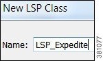
Step 4![]() Enter the name of the LSP class, and click OK.
Enter the name of the LSP class, and click OK.
Step 5![]() Click OK in the Manage QoS dialog box.
Click OK in the Manage QoS dialog box.
Assign LSP Classes to LSPs
Step 1![]() Select one or more LSPs.
Select one or more LSPs.

Step 2![]() Right-click one of these LSPs and select Properties from the context menu.
Right-click one of these LSPs and select Properties from the context menu.
Step 3![]() Select the LSP class from the Class drop-down list, and click OK.
Select the LSP class from the Class drop-down list, and click OK.
Create Mappings Between Service Classes and LSP Classes
Step 1![]() Access the Manage QoS dialog box in one of two ways.
Access the Manage QoS dialog box in one of two ways.
Step 2![]() Select the LSP Class tab.
Select the LSP Class tab.
Step 3![]() In the Service Class LSP Class Mapping section, click New.
In the Service Class LSP Class Mapping section, click New.
Step 4![]() In the Service Class drop-down list, select the service class to which you are mapping LSP classes.
In the Service Class drop-down list, select the service class to which you are mapping LSP classes.
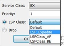
Step 5![]() Enter a priority (number) for the LSP class. This determines the order in which the demand attempts to route available LSPs. The lower the number, the higher the priority.
Enter a priority (number) for the LSP class. This determines the order in which the demand attempts to route available LSPs. The lower the number, the higher the priority.
Step 6![]() To map the selected service class to an LSP class, select the LSP Class radio button. Then select the class from the LSP Class drop-down list.
To map the selected service class to an LSP class, select the LSP Class radio button. Then select the class from the LSP Class drop-down list.
To set the mapping such that the demand should not reroute if LSPs are unavailable, select the Drop radio button. Note that Drop should only be used on the lowest priorities. Click OK, and then click OK again in the Manage QoS dialog box.
Private LSPs
WAE Design provides two ways to route selected traffic demands through specific LSPs. One way is to dedicate the traffic for specific demands to a private LSP, which is a special LSP that carries those demands only. This type of LSP models an MPLS Layer 2 VPN, providing an exclusive route for the associated demands. If the LSP goes down, all traffic associated with the LSP is interrupted.
The other way to dedicate traffic to an LSP is to filter the demands that the LSP can carry. You can do this by using the WAE Design tag feature to identify the desired demands, and then configuring the LSP with a list of tagged values. This type of LSP makes it possible to route specific types of traffic over the LSP, and the type of traffic is any arbitrary group that you define.
To configure LSPs that simulate Layer 2 VPNs, use one of these two tools.
- One tool creates dedicated demands for existing LSPs. The created demands will match the LSPs in source and destination.
- One tool creates private LSPs from existing demands. The created LSPs will match the existing demands in source and destination.
The LSP Private property is set to T (true) in the LSPs table, and the Private LSP Node and Private LSP Name properties in the Demands table are set.
Create Private Demands for Existing LSPs
LSPs must currently exist in the plan file.
Step 1![]() If you are creating demands for only selected LSPs, then select those LSPs from the LSP table. If they are tagged, you can skip this step and specify the tag value in step #3 instead. If you are creating demands for all LSPs, you can skip this step.
If you are creating demands for only selected LSPs, then select those LSPs from the LSP table. If they are tagged, you can skip this step and specify the tag value in step #3 instead. If you are creating demands for all LSPs, you can skip this step.
Step 2![]() Either select the Insert->LSPs->Demands for LSPs menu or right-click in the plot and then select New->LSPs-> Demands for LSPs menu. The Create Demands for LSPs dialog box appears.
Either select the Insert->LSPs->Demands for LSPs menu or right-click in the plot and then select New->LSPs-> Demands for LSPs menu. The Create Demands for LSPs dialog box appears.
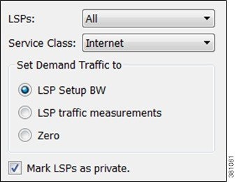
Step 3![]() In the LSPs list, select All, Selected in Table (step #1), or tag name.
In the LSPs list, select All, Selected in Table (step #1), or tag name.
Step 4![]() Select the service class to which these LSPs belong.
Select the service class to which these LSPs belong.
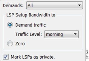
Step 5![]() Set the demand traffic to equal the LSP setup bandwidth, the LSP traffic measurements, or zero.
Set the demand traffic to equal the LSP setup bandwidth, the LSP traffic measurements, or zero.
Step 6![]() Select this option: Mark LSP as private.
Select this option: Mark LSP as private.
Step 7![]() Click OK. The newly created demands are highlighted in the Demands table.
Click OK. The newly created demands are highlighted in the Demands table.
Create Private LSPs for Demands
Demands must currently exist in the plan file. See the Traffic Demand Modeling chapter.
Step 1![]() If you are creating LSPs for only selected demands, then select those demands from the Demands table. If they are tagged, you can skip this step and specify the tag value in step #3 instead.
If you are creating LSPs for only selected demands, then select those demands from the Demands table. If they are tagged, you can skip this step and specify the tag value in step #3 instead.
Step 2![]() Either select the Insert->LSPs-> LSPs for Demands menu or right-click in the plot and then select New->LSPs->LSPs for Demands menu. The Create LSPs for Demands dialog box appears.
Either select the Insert->LSPs-> LSPs for Demands menu or right-click in the plot and then select New->LSPs->LSPs for Demands menu. The Create LSPs for Demands dialog box appears.
Step 3![]() In the Demands list, select All, Selected in Table (step #1), or tag name.
In the Demands list, select All, Selected in Table (step #1), or tag name.
Step 4![]() Set the bandwidth traffic to a specific traffic level or to zero.
Set the bandwidth traffic to a specific traffic level or to zero.
Step 5![]() Select this option: Mark LSP as private.
Select this option: Mark LSP as private.
Step 6![]() Click OK. The newly created LSPs are highlighted in the LSPs table.
Click OK. The newly created LSPs are highlighted in the LSPs table.
Configure LSPs to Transport Specific Traffic Types
This section describes how to configure LSPs that only route specific types of traffic. For example, you might want to route traffic for a voice service class through an LSP with a low latency, and route traffic for an Internet service class through another LSP with best-effort only. Such LSPs only carry the specified demands, but those demands might also be routed elsewhere.
Step 1![]() In the Demands table, select and double-click the demands that you want to group. The Properties dialog box appears.
In the Demands table, select and double-click the demands that you want to group. The Properties dialog box appears.
If a tag exists that you want to use, toggle its F (false) value to T (true) to enable the tag for the selected demands. If a tag does not exist that you want to use, click the New Tag button.
b.![]() Click OK to exit the Properties dialog box. Note, if you close without clicking OK again, the changes are not saved.
Click OK to exit the Properties dialog box. Note, if you close without clicking OK again, the changes are not saved.
Step 2![]() In the LSP table, select and double-click the LSPs that are to transport demands that were tagged (step #1). The Properties dialog box appears.
In the LSP table, select and double-click the LSPs that are to transport demands that were tagged (step #1). The Properties dialog box appears.
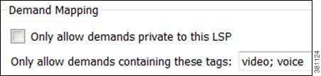
a.![]() In the Include Any Demands Tags field, enter a list of demand tags and separate each entry with a semicolon.
In the Include Any Demands Tags field, enter a list of demand tags and separate each entry with a semicolon.
Routing Inter-Area LSPs
In WAE Design, all nodes in a single AS are assumed to belong to a single IGP. If the plan file contains more than one AS, all IGPs defined in these AS’s are of the same type. For information on how nodes are assigned to areas or levels, see the IGP Simulation chapter.
An inter-area LSP is an LSP whose source node and destination node have no areas in common. If available, inter-area LSPs follow actual paths, regardless of whether doing so violates the required order of routing through areas. For example, if following an actual path, an inter-area can enter and leave an OSPF area 0 more than once.
Other factors that determine how the inter-area LSPs are routed include whether the LSP type is RSVP or SR, and whether you have selected to require explicit hops at ABRsExplicit vs. Dynamic Inter-Area LSP Routing section.)
Note![]() Inter-area Fast Reroute LSPs and inter-area IGP shortcut LSPs are not supported. If the source and destination nodes of a Fast Route LSP are in different areas, the LSP is not routed.
Inter-area Fast Reroute LSPs and inter-area IGP shortcut LSPs are not supported. If the source and destination nodes of a Fast Route LSP are in different areas, the LSP is not routed.
Order of Routing through Areas
Regardless of the LSP type and whether explicit hops are required, inter-area LSPs route through the backbone areas, as follows, where “backbone” means area 0 for OSPF or the Level 2 area for IS-IS.
- If there are three or more areas, backbone areas must be between the source and destination nodes. Typically, there are no more than three areas and therefore, the backbone area must be in the middle. For example, an OSPF inter-area LSP would route from area 1 to area 0 (backbone) and then to area 2 (Figure 10-9).
- If there are only two areas, there can only be one backbone area, and either the source or the destination node must be in the backbone area.
Explicit vs. Dynamic Inter-Area LSP Routing
There are two modes of routing inter-area LSPs. One requires that explicit hops be set on ABR nodes. This mode correctly simulates actual router behavior where ABR explicit hops are required. The other mode does not require explicit hops at ABR nodes and can route an LSP fully dynamically across multiple areas. While this mode does not simulate actual router behavior, it is useful for planning inter-area LSP routes. For instance, you can use a fully dynamic simulation to find an appropriate path, which can then be converted into a (routable) fully explicit path using other tools such as the Explicit LSP Paths initializer. These modes are specified using the network option labeled “LSP routing requires ABR explicit hops.”
If this option is selected, inter-area LSPs are routed based on explicit hops set on the ABR nodes.
- An inter-area RSVP LSP must contain a named path, and the named path must contain explicit hops at ABRs for each required area crossing.
- An inter-area SR LSP must contain a segment list, and the segment list must contain explicit node hops at ABRs for each required area crossing.
If this option is not selected, inter-area LSPs are routed dynamically and explicit hops at ABRs are not required. To leave one area and enter another, the inter-area LSP routes to the closest ABR in the current area that also borders the area it is entering.
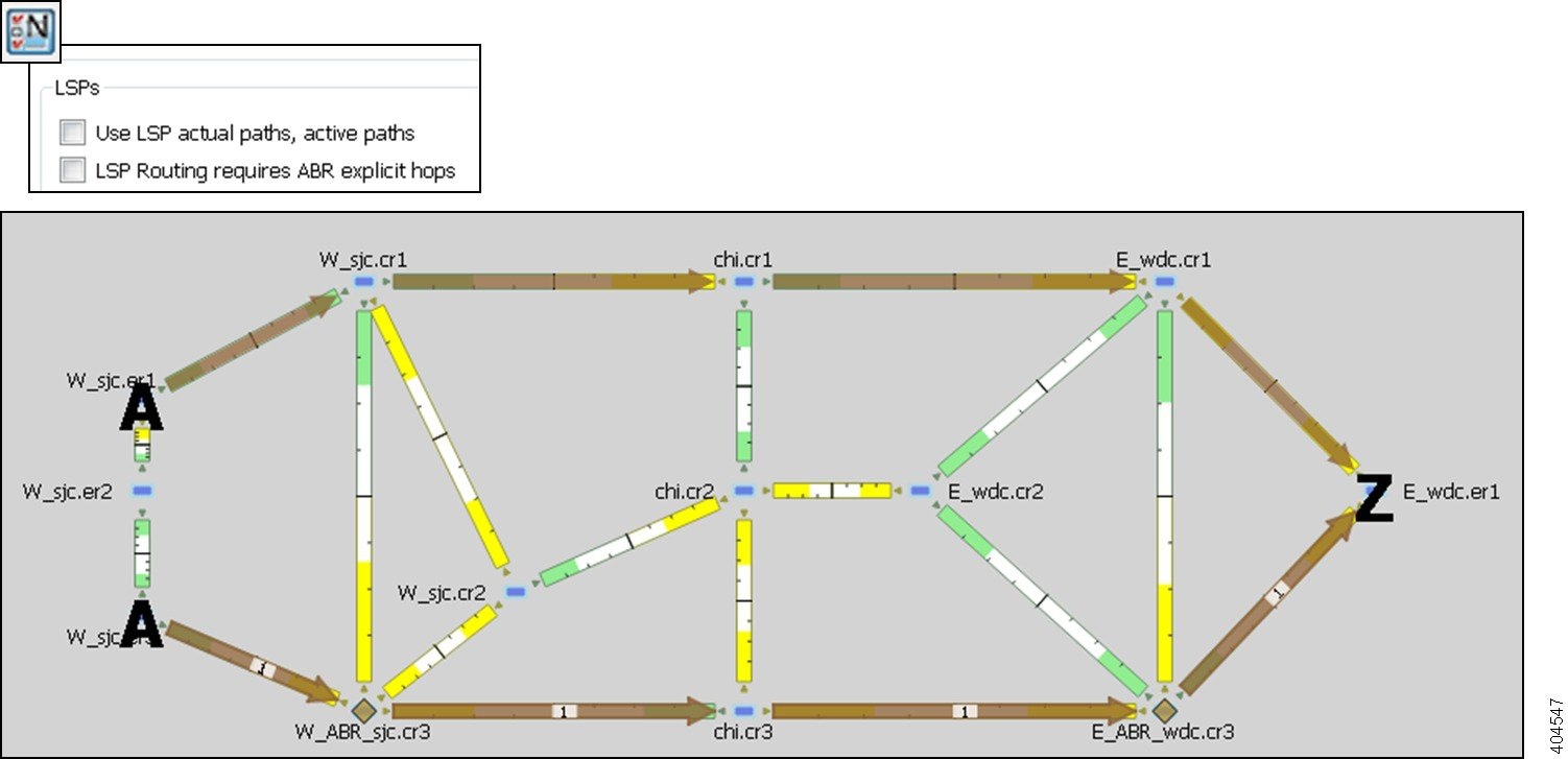
Example: Figure 10-9 shows two inter-area LSPs selected, although only the LSP with explicit hops set on ABR nodes routes. The reason is because the network option is set to require ABR hops when routing inter-area LSPs. Figure 10-10 shows that by deselecting this network option, the inter-area LSP that does not have hops set at ABRs can dynamically route.
Figure 10-9 Example Inter-Area Routing Requiring Hops at ABRs
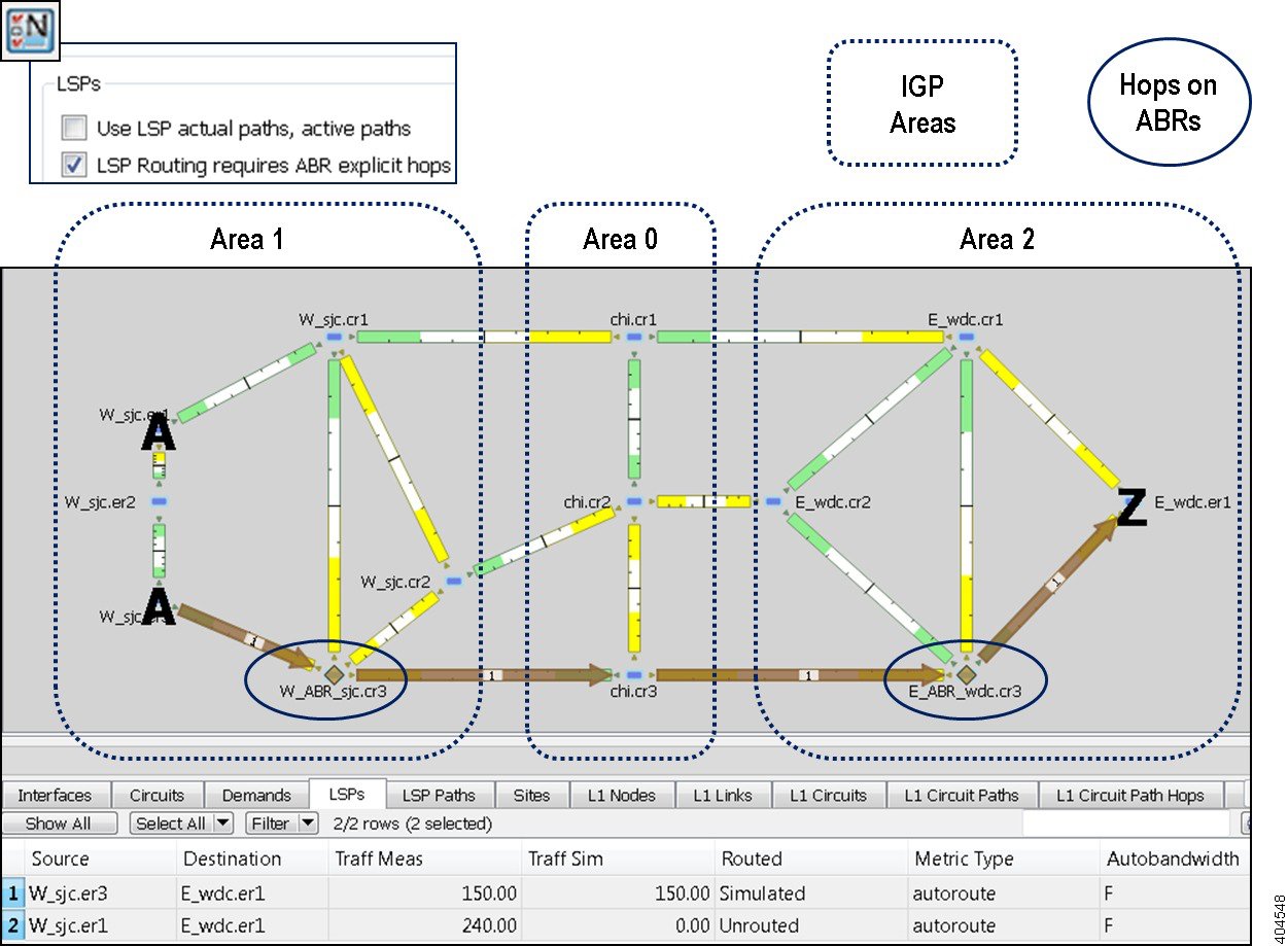
Figure 10-10 Example Inter-Area Routing without Requiring ABRs
Simulation Modes
WAE Design enables you to set several global parameters that affect how LSPs are routed or rerouted. To access these options, either select the Edit->Network Options menu or click the Network Options icon in the Visualization toolbar. Then select the Simulation tab.

By default, WAE Design simulates the state of the network once it has fully responded to a failure. Specifically, this is the network state after LSPs have re-established new routes around the failure, and the IGP has fully reconverged. This is called the IGP and LSP Reconvergence simulation mode.
Other simulation modes include Fast Reroute (FRR), Autobandwidth Convergence, and Autobandwidth Convergence Including Failures. For information, see the RSVP-TE Simulation chapter. For information on the network option for rerouting of non-standby L1 circuit paths under failure, see the Layer 1 Simulation chapter.
The Optimization tools only work in IGP and LSP Reconvergence mode. If you attempt to run one while in a different convergence mode, you are prompted whether to continue, and if you do, the simulation changes to IGP and LSP Reconvergence mode.
The status bar in the lower, left of the GUI identifies which simulation modes you are currently using. Note that unless specified otherwise, the documentation describes behavior in the IGP and LSP Reconvergence mode.
LSP Establishment Order
WAE Design establishes LSPs in the order in which they appear in the plan. Thus, the routing of a specific LSP might depend on previously established LSP routes. You can modify this order by changing a random seed. WAE Design then establishes LSPs in a random order that is completely determined by this number. Although you cannot predict the order based on the number, if you use the same number multiple times, WAE Design establishes the LSPs in the same order each time. Varying the LSP establishment order enables you to check, for example, whether certain orders result in higher utilizations.
Step 1![]() Either select the Edit->Network Options menu or click the Network Options icon in the Visualization toolbar.
Either select the Edit->Network Options menu or click the Network Options icon in the Visualization toolbar.
Step 2![]() Select the Simulation tab.
Select the Simulation tab.
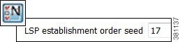
Step 3![]() In the LSPs section, enter a number in the “LSP establishment order seed” field. The default is 0.
In the LSPs section, enter a number in the “LSP establishment order seed” field. The default is 0.
Reports and Diagnostics
LSP Path Reports
You can create reports on the LSP path routes that the LSP is actually taking across both L3 and L1 topologies. Each report identifies the complete path route, as well as disjointness information, including whether it contains common nodes or common circuits. Additionally, the report contains all other columns in an LSP Paths table, though they are initially hidden.
Step 1![]() Select one or more LSP paths. If you do not select one, the all LSP paths are used.
Select one or more LSP paths. If you do not select one, the all LSP paths are used.
Step 2![]() Select the Tools->Reports->LSP Path Routes menu.
Select the Tools->Reports->LSP Path Routes menu.
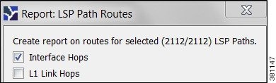
Step 3![]() Select one or both hop options, and click OK.
Select one or both hop options, and click OK.
After closing the report, you can access it again by selecting the Windows->Reports menu.
To export the report, right-click the Routes report name in the left Reports navigation pane, and select Export Routes.
Simulation Diagnostics
To help troubleshoot RSVP LSP and LSP path simulations, WAE Design analyzes simulation routes and provides reasons for certain types of routing behavior. The Simulation Diagnostics tool identifies why an LSP is not routed, why an LSP is routed away from its actual path, and why an LSP is not following the shortest TE path.
These routing diagnostics assume that all other LSPs, except for the one being tested, have been routed. That is, WAE Design calculates whether an LSP can route on the actual path after all other routed LSPs have had their bandwidth reserved.
Note that running a report overwrites the previous report of the same type. For example, an LSPs diagnostic report would overwrite the previous LSPs report, but not the LSP Path diagnostic report.
Using Simulation Diagnostics to Troubleshoot
In the “Reason” column, information is provided to help you troubleshoot the LSP and LSP path issues.
Run LSP Simulation Diagnostics
Step 1![]() Either select one or more LSPs or LSP paths from their respective tables.
Either select one or more LSPs or LSP paths from their respective tables.
Step 2![]() Open the diagnostics information in one of two ways.
Open the diagnostics information in one of two ways.
Related Topics
- RSVP-TE Simulation chapter
- Segment Routing Simulation chapter
- Traffic Demand Modeling chapter
- RSVP-TE Optimization chapter
- Explicit and Tactical RSVP-TE LSP Optimization chapter
- SR-TE Optimization chapter
- SR-TE Bandwidth Optimization chapter
- LSP Disjoint Path Optimization chapter
- LSP Loadshare Optimization chapter
 Feedback