- Overview
- Plan Files and Patch Files
- User Interface
- Plan Objects
- Traffic Demand Modeling
- Simulation
- Simulation Analysis
- Forecasting Traffic
- IGP Simulation
- MPLS Simulation
- RSVP-TE Simulation
- Segment Routing Simulation
- Layer 1 Simulation
- Quality of Service Simulation
- BGP Simulation
- Advanced Routing with External Endpoints
- VPN Simulation
- Multicast Simulation
- Metric Optimization
- RSVP-TE LSP Optimization
- LSP Optimization
- SR-TE Optimization
- SR-TE Bandwidth Optimization
- LSP Disjoint Path Optimization
- LSP Setup Bandwidth Optimization
- LSP Loadshare Optimization
- Capacity Planning Optimization
- Changeover
- Patch Files
- Reports
- Cost Modeling
- Plot Legend for Design Layouts
Cisco WAE Design 6.4 User Guide
Bias-Free Language
The documentation set for this product strives to use bias-free language. For the purposes of this documentation set, bias-free is defined as language that does not imply discrimination based on age, disability, gender, racial identity, ethnic identity, sexual orientation, socioeconomic status, and intersectionality. Exceptions may be present in the documentation due to language that is hardcoded in the user interfaces of the product software, language used based on RFP documentation, or language that is used by a referenced third-party product. Learn more about how Cisco is using Inclusive Language.
- Updated:
- June 29, 2016
Chapter: Capacity Planning Optimization
Capacity Planning Optimization
As demand grows on your network you need a way to address the additional traffic and congestion that these demands create. To alleviate congestion, you can:
- Upgrade existing circuits by adding more capacity to them
- Augment these circuits with associated port circuits
- Add parallel circuits to existing circuits
- Specify new adjacencies between nodes that were not initially connected
To perform these planning optimization investigations, WAE Design includes a capacity planning optimization tool. The goal of a capacity planning optimization is to minimize the addition of any required capacity to be installed on the network. The capacity planning optimizer operates on both Layer 1 and Layer 3 network elements, as well as across failure sets, so you can use a combination of elements in a layered fashion to reach an acceptable solution to meet maximum utilization requirements.
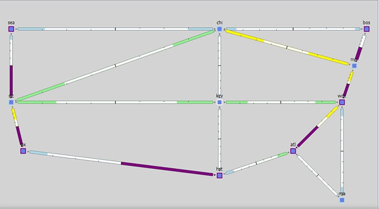
Figure 27-1 shows an example of a network design before optimization, where extra demands were placed on the network. As a result, you can see several congested interfaces in purple.
Figure 27-1 Design Before Optimization
Procedure Overview
There are several optimization parameters that you can set to relieve network congestion and augment capacity, depending on your goals. It starts with defining a maximum utilization threshold for a specified set of interfaces and then layering additional options that operate on Layer 3, Layer 1, and across failure sets.

Note![]() Some of the optimizer options that you can choose are mutually exclusive, for example, if you tell the optimizer to create port circuits, then it cannot create parallel circuits at the same time, and vice-versa, while other options are complementary. For example, you can specify the creation of parallel circuits and new adjacencies together.
Some of the optimizer options that you can choose are mutually exclusive, for example, if you tell the optimizer to create port circuits, then it cannot create parallel circuits at the same time, and vice-versa, while other options are complementary. For example, you can specify the creation of parallel circuits and new adjacencies together.
Step 1![]() Navigate to Tools > Capacity Planning Optimization. By default, the optimizer presents you with Layer 3 optimization options.
Navigate to Tools > Capacity Planning Optimization. By default, the optimizer presents you with Layer 3 optimization options.
Figure 27-2 Capacity Planning Optimization Tool
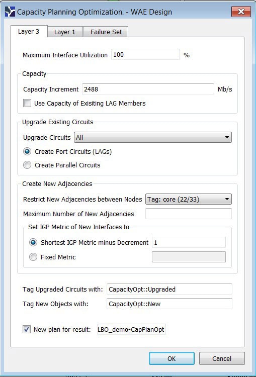
Step 2![]() In the Layer 3 tab, define the maximum utilization threshold that you want to use for all interfaces in the network. By default, the optimizer sets this threshold at 100% congestion.
In the Layer 3 tab, define the maximum utilization threshold that you want to use for all interfaces in the network. By default, the optimizer sets this threshold at 100% congestion.
Step 3![]() Decide on the Layer 3 optimization options to use. See Table 27-1 for all of the Layer 3 options and field descriptions.
Decide on the Layer 3 optimization options to use. See Table 27-1 for all of the Layer 3 options and field descriptions.
Note![]() You can specify both the capacity increment and the existing capacity of LAG circuits in tandem.
You can specify both the capacity increment and the existing capacity of LAG circuits in tandem.
–![]() Set the Capacity Increment (the default is 100000 Mb/s).
Set the Capacity Increment (the default is 100000 Mb/s).
–![]() Use the capacity of existing LAG Members. This tells the optimizer to copy and use the existing (same capacity) as those LAG members in the design when it creates new port circuits.
Use the capacity of existing LAG Members. This tells the optimizer to copy and use the existing (same capacity) as those LAG members in the design when it creates new port circuits.
You can upgrade all existing circuits or a subset of these circuits (the default is to upgrade all circuits). If you want to allow the upgrade of just certain circuits, then indicate those circuits to be modified. This is useful if you want to limit your upgrades to a certain geographical location in the network.
Note![]() You can create new port circuits or new parallel circuits, but not both at the same time.
You can create new port circuits or new parallel circuits, but not both at the same time.
To create new port circuits or parallel circuits, select one of the following options:
–![]() Create new port circuits (LAGs). In this case, the optimizer augments the existing circuits with associated port circuits (LAGs) with additional port circuits. The optimizer converts non-LAG circuits to LAGs.
Create new port circuits (LAGs). In this case, the optimizer augments the existing circuits with associated port circuits (LAGs) with additional port circuits. The optimizer converts non-LAG circuits to LAGs.
–![]() Create new parallel circuits. In this case, the optimizer creates new circuits that are parallel to existing circuits.
Create new parallel circuits. In this case, the optimizer creates new circuits that are parallel to existing circuits.
By default, the optimizer does not create new adjacencies. If you specify a set of candidate nodes for it to use, then the optimizer proposes new adjacencies. The optimizer restricts a new adjacency between the specified candidate nodes. For example, you might require that only core nodes be directly connected. In this case, specify only core nodes as your candidate nodes. Additionally, you can impose a limit on the maximum number of new adjacencies that the optimizer creates.
–![]() Select all the nodes in the table or just a subset of the nodes that you want to optimize.
Select all the nodes in the table or just a subset of the nodes that you want to optimize.
–![]() Specify the Maximum Number of New Adjacencies threshold.
Specify the Maximum Number of New Adjacencies threshold.
Note![]() You can apply the IGP metric to new adjacencies, but not to parallel circuits.
You can apply the IGP metric to new adjacencies, but not to parallel circuits.
–![]() Specify the IGP metric type for new interfaces, which can be either:
Specify the IGP metric type for new interfaces, which can be either:
Decrement (default): The metric of new interfaces is equal to the shortest path minus the value specified in the metric option.
Fixed: The metric of new interfaces is equal to the value specified in the Fixed Metric field.
Step 4![]() (Optional) On the Layer 1 tab, click Create L1 Circuits. See Table 27-2 for the Layer 1 options and see Creating Layer 1 Circuits for more information.
(Optional) On the Layer 1 tab, click Create L1 Circuits. See Table 27-2 for the Layer 1 options and see Creating Layer 1 Circuits for more information.
Step 5![]() (Optional) On the Failure Set tab, select one or more options to provide additional capacity planning failure options. See Adding Failure Set Options for more information.
(Optional) On the Failure Set tab, select one or more options to provide additional capacity planning failure options. See Adding Failure Set Options for more information.
Step 6![]() (Optional) Override the defaults for how circuits are tagged or for how new optimized plan files are named.
(Optional) Override the defaults for how circuits are tagged or for how new optimized plan files are named.
Step 7![]() Click OK. This runs the optimizer and creates the capacity planning optimization reports.
Click OK. This runs the optimizer and creates the capacity planning optimization reports.
WAE Design routes all the traffic and looks at the utilization threshold you specified, and any other optimization parameters you specified. After running an optimization, you can look at the summary report to see what the optimizer did to remove congestion. The key metric to look at is the Total Capacity Added (Mb/s) number after the Options section of the report.
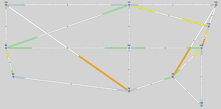
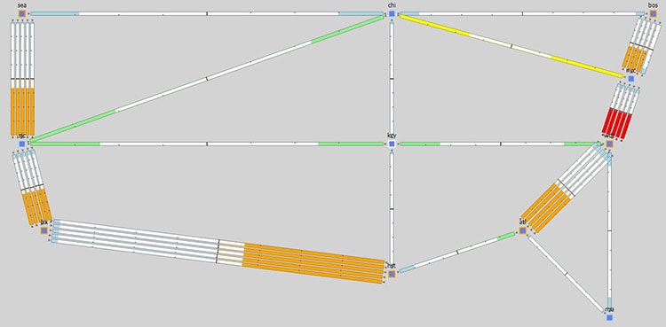
Figure 27-3 shows the design after optimization using the parameters specified in Figure 27-2. In this case, the optimizer proposes to set up two new adjacencies:
Figure 27-3 Design After Optimization
Reports
The reports window provides both a summary report and a capacity upgrades table.
Summary Report Example
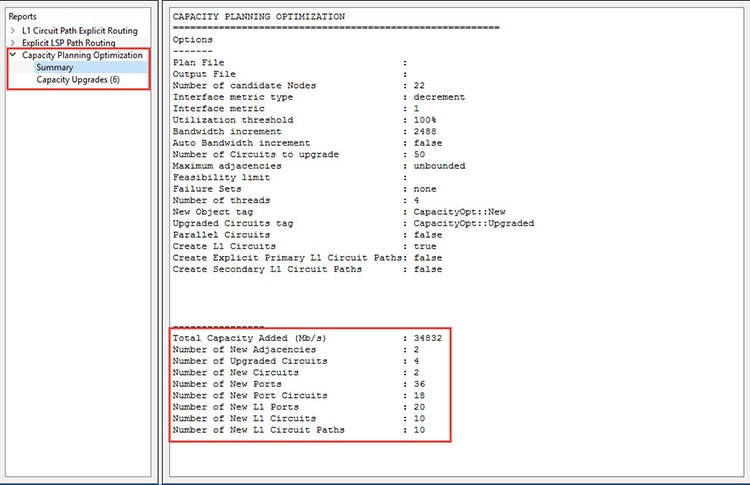
After running the optimization, the summary reports provide useful metrics at a glance. Using the previous design as an example with the default utilization threshold of 100%, the decrement interface metric type, and unbounded adjacencies, this report provides details on:
- the total capacity added as a result of the optimization (in this example, 34832 Mb/s)
- the number of new adjacencies (in this example, 2)
- the number of upgraded circuits (in this example, 4)
- the number of new circuits (in this example, 2)
- the number of new ports (in this example, 36)
- the number of new port circuits (in this example, 28)
- the number of new L1 ports (in this example, 20)
- the number of new L1 circuits (in this example, 10)
- the number of new L1 circuit paths (in this example, 10)
Figure 27-4 After Optimization Summary Report Example
Capacity Upgrades Report Example
You can get additional details on how the optimizer upgraded circuits by clicking on the Capacity Upgrades report option. Using the previous optimized design as an example and using the default utilization threshold of 100%, the decrement interface metric type, and unbounded adjacencies, this report provides details on the 6 circuit upgrades that it suggests to meet your optimization parameters.
Figure 27-5 After Optimization Capacity Upgrades Report Example
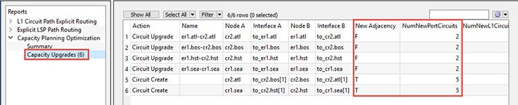
In this example, you can see out of the 6 upgrades listed, there were two new port circuits created for each upgraded circuit.
Layer 3 Optimization Options
There are several Layer 3 options that you can use to help you with different capacity planning scenarios. These parameters tell the optimizer what your preferences are in terms of utilization thresholds, capacity increments, and whether the optimizer should upgrade existing circuits, create new adjacencies between nodes, create port circuits, or create parallel circuits.
Note![]() You can use the Layer 3 options along with the Layer 1 and Failure Set options to create a multi-layer design and a more robust network.
You can use the Layer 3 options along with the Layer 1 and Failure Set options to create a multi-layer design and a more robust network.
|
|
|
|---|---|
Defines the congestion threshold for all interfaces in the network. By default, the capacity planning optimizer sets this value at 100% utilization. However, for future planning purposes, you may want to set the utilization to a lower number, for example, 90%. |
|
Defines the bandwidth increment value, that is, the allowed capacity increment in Mb/s. You can think of this value as the capacity of the ports. The default is 100000 Mb/s. |
|
Tells the optimizer to augment capacity based on the capacity already defined in the existing LAG Members instead of using the Capacity Increment. |
|
Tells the optimizer to upgrade all circuits, or just a subset of circuits or those circuits with certain tags to reduce congestion. By default, the optimizer assumes that you want to upgrade all circuits. To indicate that you want to use a subset of these circuits, you can select them using tags or by selecting a subset of them from the WAE Design tables. |
|
Tells the optimizer to create port circuits to reduce congestion. If a non-lag circuit is upgraded, the optimizer creates a port circuit with the initial capacity (existing L1 circuits are reassigned to this port circuit) and new port circuits are created. If you create port circuits, you cannot also create parallel circuits and vice versa. |
|
Tells the optimizer to create parallel circuits to reduce congestion. If you tell the optimizer to create parallel circuits, you cannot also tell it to create port circuits and vice versa. For more information, see Parallel Circuits Design Example. |
|
By default, the optimizer does not create new adjacencies. If you specify a set of candidate nodes for it to use, then the optimizer proposes new adjacencies. The optimizer restricts a new adjacency between the specified candidate nodes. For example, you might require that only core nodes be directly connected. In this case, specify only core nodes as your candidate nodes. |
|
Tells the optimizer the maximum number of adjacencies to create between candidate nodes. By default, this is an unbounded number. |
|
Set IGP Metric of New Interface to Shortest IGP Metric minus Decrement |
Tells the optimizer to set the IGP metric of the interfaces corresponding to new adjacencies to be the shortest IGP metric minus the decrement of 1. This is how the IGP metric of such interfaces is set by default. The IGP metric of new interfaces due to parallel circuit upgrades is the same as the metric of the parallel interfaces. |
Defines a fixed IGP metric to use when creating new interfaces. Enter a positive integer as a value in this field. |
|
Use this field to tag any upgraded circuits. By default, the optimizer tags upgraded circuits with the label: CapacityOpt::Upgraded. |
|
Use this field to tag for any new objects the optimizer creates. By default, the optimizer tags upgraded circuits with the label: CapacityOpt::New. |
|
Use this field to enter a name for the creation of a new plan file with the optimization results. By default, the optimizer appends the input plan file name with: -CapPlanOpt in the GUI. |
Parallel Circuits Design Example
Figure 27-6 shows the first design in this chapter with parallel circuits added to increase capacity. In this case, the optimizer proposes five sets of parallel circuits:
- one between Houston (hst) and Los Angeles (lax)
- one between Los Angeles (lax) and San Jose (sjc)
- one between San Jose (sjc) and Seattle (sea)
- one between Boston (bos) and New York City (nyc)
- one between Atlanta (atl) and Washington, D.C. (wdc)
Because the utilization threshold was set to 100%, utilizations over 90% (colored in red) are acceptable solutions.
Figure 27-6 Adding Parallel Circuits to Increase Capacity
Layer 1 Optimization Options
The Capacity Planning Optimization Layer 1 options tell the optimizer to create new L1 circuits.
Note![]() You can use the Layer 1 options on top of the Layer 3 and Failure Set options to create a multi-layer design and a more robust network.
You can use the Layer 1 options on top of the Layer 3 and Failure Set options to create a multi-layer design and a more robust network.
Creating Layer 1 Circuits
If you know exactly where you want to place L1 circuits, you can use explicit routing. To simulate optical restoration capabilities, you can create secondary L1 circuit paths.
Step 1![]() In the Capacity Planning Optimization tool, select the Layer 1 tab.
In the Capacity Planning Optimization tool, select the Layer 1 tab.
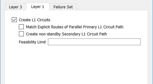
Step 2![]() Select Create L1 Circuits. This enables the additional Layer 1 options and the Feasibility Limit field.
Select Create L1 Circuits. This enables the additional Layer 1 options and the Feasibility Limit field.
Step 3![]() (Optional) Select whether you want to use explicit routing or to create secondary L1 circuit paths when creating the L1 Circuits or specify both options. See Table 27-2 for the Layer 1 options.
(Optional) Select whether you want to use explicit routing or to create secondary L1 circuit paths when creating the L1 Circuits or specify both options. See Table 27-2 for the Layer 1 options.
Step 4![]() (Optional) Enter a positive integer in the Feasibility Limit field.
(Optional) Enter a positive integer in the Feasibility Limit field.
Failure Set Optimization Options
When performing a capacity planning optimization, it is often the case that you need to consider failure scenarios. Under failure events, the optimizer reroutes demands, which leads to network congestion. By default, the optimizer does not take these failures into consideration. If you specify a failure set, then the optimizer considers all of the failures with the failure set and proposes capacity upgrades so that there is no congestion under any specified failure event. This enables you to plan for more robust networks.
This is similar to running a worst-case simulation analysis in that it adds more fail-safe scenarios to your capacity plan.
Note![]() You can use the Failure Set options on top of the Layer 1 and Layer 3 options to create a multi-layer design and a more robust network.
You can use the Failure Set options on top of the Layer 1 and Layer 3 options to create a multi-layer design and a more robust network.
Adding Failure Set Options
Step 1![]() In the Capacity Planning Optimization tool, select the Failure Set tab.
In the Capacity Planning Optimization tool, select the Failure Set tab.
Step 2![]() Select one or more failure sets that you want the optimizer to consider:
Select one or more failure sets that you want the optimizer to consider:
Certain entries appear grayed out if they are not available in your design plan. In the next example, the plan file does not include SRLGs or External Endpoint Members.
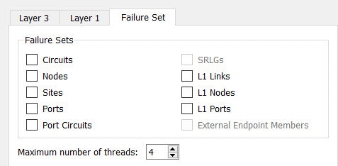
Step 3![]() (Optional) Specify the Maximum number of threads.
(Optional) Specify the Maximum number of threads.
By default, the optimizer attempts to set this value to the optimal number of threads based on the available cores.
This action runs the optimizer and creates the capacity planning optimization report showing the results of the increased capacity. You can view additional capacity information on the Capacity Upgrades report.
Related Topics
- Simulation Analysis chapter
- SR-TE Bandwidth Optimization
- Plan Objects (for creating tags)
 Feedback