Customizing FlowCollector
Available Languages
Table Of Contents
Before You Begin:
FlowCollector Configuration and Resource FilesUnderstanding FlowCollector Data Collection and Aggregation
Defining Source and Destination Port Numbers
Defining Source and Destination Autonomous System Numbers
Modifying FlowCollector Resources
Increasing UDP Socket Receive Buffer Size
Mapping a List of IP Addresses to One IP Address or Label
Preventing FlowCollector from Accepting Unsolicited Packets
Retaining Router IP Addresses for Switched Export Packets
Using a User-Defined Script to Process FlowCollector Data Files
Changing the Output Buffer Size
NF_Thread Data File and Disk Space Parameters
Parameters in the nf.resources File
Unsolicited Event Notifications
Customizing FlowCollector
This chapter describes how to customize FlowCollector operations using thread, filter, and protocol definitions, lists of port and autonomous system numbers, and other FlowCollector configuration parameters.
This chapter includes the following sections:
•
Before You Begin: FlowCollector Configuration and Resource Files
•
•
•
•
•
Before You Begin:
FlowCollector Configuration and Resource FilesThe process of customizing FlowCollector operation involves changes and additions to one or more of the following FlowCollector configuration and resource files located in the $NFC_DIR/config directory:
•
•
•
•
•
•
•
•

Note
You can also use the interactive features of the NFUI to add, modify, or delete thread definitions (nfconfig.file file) and add or delete filter definitions (nfconfig.file file) or protocol definitions (nfknown.protocols file). For details on the use of the NFUI, see "Using the FlowCollector User Interface," for more information.
nfconfig.file
The nfconfig.file contains definitions of the aggregation tasks that collect and aggregate data exported from NetFlow export devices in your network. These aggregation tasks, defined in terms of threads and filters, tell FlowCollector how to collect and aggregate the incoming NetFlow export data. Each aggregation task must have a thread defined for it (filters are optional).
For more information about creating or modifying threads and filters, see the "Understanding FlowCollector Data Collection and Aggregation" section.
nfknown.protocols
The nfknown.protocols file contains definitions of recognized application layer protocols (FTP, Telnet, and so forth) for use in aggregating data. These definitions are also used for protocol filters. You edit this file to add or remove protocol definitions. FlowCollector scans this file and maintains a list of protocols it finds. FlowCollector searches the protocols in the order that they are defined in the nfknown.protocols file.
Note
For more information about creating or modifying protocols, see the "Defining Protocols" section.
nfknown.srcports
The nfknown.srcports file contains transport layer source TCP or UDP port numbers used in the SourcePort aggregation scheme (or any other aggregation scheme using source port numbers as part of its key). These TCP or UDP port numbers correspond to the port numbers defined in RFC 1700; for example, Telnet = 23, and FTP = 20 or 21.
Flow records having source ports that match defined values in the nfknown.srcports file are aggregated together. Flow records from source ports not defined in this file are aggregated under "Others."
For more information about creating or modifying source port numbers, see the "Defining Source and Destination Port Numbers" section.
nfknown.dstports
The nfknown.dstports file contains destination port numbers used in any aggregation scheme that includes destination port numbers as part of its key.
Flow records having destination ports that match defined values in the nfknown.dstports file are aggregated together. Flow records from destination ports not defined in this file are aggregated under "Others."
For more information about creating or modifying destination port numbers, see the "Defining Source and Destination Port Numbers" section.
nfknown.srcasns
The nfknown.srcasns file contains source autonomous system numbers, either origin or peer, used in any aggregation scheme that includes source autonomous system numbers as part of its key.
Flow records having source autonomous system numbers that match defined values in the nfknown.srcasns file are aggregated together. Flow records from source autonomous system numbers not defined in this file are aggregated under "Others."
For more information about creating or modifying source autonomous system numbers, see"Defining Source and Destination Autonomous System Numbers" section.
nfknown.dstasns
The nfknown.dstasns file contains destination autonomous system numbers, either origin or peer, used in any aggregation scheme that includes destination autonomous system numbers as part of its key.
Flow records having destination autonomous system numbers that match defined values in the nfknown.dstasns file are aggregated together. Flow records from destination autonomous system numbers not defined in this file are aggregated under "Others."
For more information about creating or modifying destination autonomous system numbers, see"Defining Source and Destination Autonomous System Numbers" section.
nf.resources
The nf.resources file contains the variables and corresponding directory file path names used to configure your startup FlowCollector environment. Besides the path names, the nf.resources file also includes a number of configuration parameters for tuning FlowCollector performance and behavior.
For more information about this file, see "Modifying FlowCollector Resources" section.
nfcd.config
The nfcd.config file contains the parameters needed by FlowCollector to automatically start NFCollector and NFCGW upon system startup, automatically restart NFCollector and NFCGW if they terminate abnormally, and set the scheduling priorities of NFCollector and NFCGW.
For more information, see "Configuring the Daemon (NFCD)" section.
Understanding FlowCollector Data Collection and Aggregation
FlowCollector collects and summarizes (aggregates) data into data files based on user-defined criteria specified in a FlowCollector thread. A thread is an aggregation task defined by a set of user-configurable attributes that specify how FlowCollector aggregates the traffic flows stored on the workstation. Two key thread attributes are:
•
•
Figure 5-1 shows an example of how FlowCollector uses threads and filters. In this example, threadA uses filterA and the SourceNode aggregation scheme; threadB uses both filterA and filterB (filters can be shared among threads) and the DestPort aggregation scheme; threadC does not use any filters, but it also uses the DestPort aggregation scheme.
Figure 5-1 NetFlow FlowCollector Data Aggregation Example
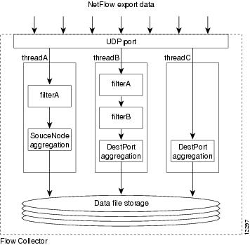
The following nfconfig.file file example contains the thread definitions to accomplish the general data aggregation scheme shown in Figure 5-1. The file contains two filter definitions (filterA and filterB) and three thread definitions (threadA, threadB, and threadC) to accomplish the aggregation. NetFlow export traffic arrives on FlowCollector UDP port 9991. Data is to be aggregated by the following aggregation schemes:
•
•
Filter filterApermit nexthop 172.16.23.65 0.0.0.0Filter filterBdeny srcaddr 172.16.0.0 0.0.255.255permit srcaddr 0.0.0.0 0.0.0.0Thread threadAFilter filterAAggregation SourceNodePeriod 10Port 9991State ActiveDataSetPath /opt/CSCOnfc/DataCompression NoBinary NoMaxUsage 500Thread threadBFilter filterAFilter filterBAggregation DestPortPeriod 10Port 9991State ActiveDataSetPath /opt/CSCOnfc/DataCompression NoBinary NoMaxUsage 500Thread threadCAggregation DestPortPeriod 10Port 9991State ActiveDataSetPath /opt/CSCOnfc/DataCompression NoBinary NoMaxUsage 500In the example, threadA uses filterA to include only the traffic passing through the export device 172.16.23.65, whereas threadB uses both filters-filterA to include only the traffic passing through the export device 172.16.23.65, and filterB to exclude traffic from network 172.16.0.0. All three threads flush their aggregated data every 10 minutes into data files saved in the /opt/CSCOnfc/Data directory.
Creating a Filter
A filter defines which flow data is to be included or excluded as FlowCollector aggregates data. The default condition for a filter is to deny (exclude) the flow.
The syntax for a filter definition is as follows:
filter filter-name{permit|deny} type value mask...{permit|deny} type value maskwhere:
Filter
Keyword that identifies the definition as a filter.
filter-name
The unique, user-specified name of the filter. The name can be up to 16 alphanumeric characters.
permit
The keyword that keeps the data that matches the specified filter type and value.
deny
The keyword that rejects the data that matches the specified filter type and value (matching flow data is ignored and not aggregated).
type
The filter type. See Table 5-1 for a description of filter types.
value
The value associated with the filter type. All filter types require a value. See Table 5-1 for a description of filter types and values.
mask
Required if the filter uses the srcaddr, dstaddr, or nexthop type. The IP netmask that qualifies the IP address used as value. See Table 5-1 for a description.
Filter keyword and variable entries are not case sensitive. Figure 5-1 describes the default filter types provided with FlowCollector, the type of input required for the value, and whether the value requires a mask.
Table 5-1 Filter Types, Values, and Their Descriptions
Requiredsrcaddr
Source IP address
Yes
Filter the input data based on the source IP address. If you use this type, you must provide the IP netmask that qualifies the source IP address.
dstaddr
Destination IP address
Yes
Filter the input data based on the destination IP address. If you use this type, you must provide the IP netmask that qualifies the destination IP address.
srcport
Source port number
No
Filter the input data based on the source port number.
dstport
Destination port number
No
Filter the input data based on the destination port number.
srcinterface
Source interface number
No
Filter the input data based on the source interface number.
dstinterface
Destination interface number
No
Filter the input data based on the destination interface number.
nexthop
Next hop IP address
Yes
Filter the input data based on the next hop IP address. If you use this type, you must provide the IP netmask that qualifies the next hop IP address.
protocol
Protocol name
No
Filter the input data based on the protocol definitions in the nfknown.protocols file.
For more information on protocol definitions, see Defining Protocols.
prot
Protocol number
No
Filter the input data based on the protocol number in the flow record, where the protocol number corresponds to a protocol specified in the /etc/protocols file of your workstation.
ToS
Type of service
No
Filter the input data based on the type of service (ToS).
srcas
Source AS
No
Filter the input data based on the autonomous system number of the source, either origin or peer.
dstas
Destination AS
No
Filter the input data based on the autonomous system number of the destination, either origin or peer.
When defining a filter, keep in mind the following qualifications:
•
filter kill-wwwdeny Dstport 80In this example, all flows going to port 80 and all other flows are denied. If you want to deny flows to port 80 only, but permit all other flows, you need an explicit wildcard entry to permit the other flows. For example:
filter kill-wwwdeny Dstport 80permit Dstaddr 0.0.0.0 255.255.255.255•
Filter filterApermit Srcaddr 172.16.1.24 0.0.0.255deny Srcaddr 192.168.0.0 0.0.255.255deny Srcport 53permit Dstaddr 0.0.0.0 255.255.255.255If you want to permit traffic from network 172.16.1.0, but deny traffic coming from port 53, you should change the order of the filter conditions as follows:
Filter filterAdeny Srcaddr 192.168.0.0 0.0.255.255deny Srcport 53permit Srcaddr 172.16.1.24 0.0.0.255permit Srcaddr 0.0.0.0 255.255.255.255The last filter condition overrides the default behavior, which calls for denying all flows that do not match any of the first three filter conditions.
Creating a Thread
A thread is a set of defined attributes that tells FlowCollector how to aggregate the traffic flows stored on the workstation.
Note
The syntax for a thread definition is as follows:
Thread thread-name[Filter filter-name]...[Filter filter-name]Aggregation schemePeriod minutesPort valueDataSetPath directory-pathState active|inactiveCompression yes|noBinary yes|noMaxUsage megabytes
Note
The keywords and their arguments are listed on separate lines for legibility. Keyword and argument entries are not case sensitive. Table 5-2 lists thread attributes and variables.
Table 5-2 Attributes and Variables for Creating a Thread
Thread
thread-name
Unique, user-defined name of the thread. Can be up to 16 alphanumeric characters.
Filter
filter-name
(Optional.) Unique name of a previously defined filter. You can specify one or more filters in a thread definition. When more than one filter is specified in a thread, the result is a logical AND of the functions defined in the filters.
Filters can be shared among threads. For more information on filters, see the previous section, "Creating a Filter" section.
Aggregation
scheme
A way to summarize data collected by FlowCollector. For more information about aggregation schemes, see the "Aggregation Schemes" section.
Period
minutes
The frequency, in minutes, for how often FlowCollector writes aggregated data from its memory buffers into a data file. Data received in each period is written into a separate file. For example, setting the period to 30 minutes generates two data files every hour.
Port
Value
UDP port number on which FlowCollector is expecting NetFlow data from NetFlow export devices. The valid range of ports is between 1024 and 65535.
In a default FlowCollector installation, UDP ports 9995 and 9996 are automatically configured as the UDP ports FlowCollector uses to receive NetFlow exported data. These numbers are defined in the default set of threads provided as part of the FlowCollector installation. You can define other UDP port numbers by selecting a number in the range 1024 to 65535 and using that number as the value in the Port attribute of an active thread definition.
DataSetPath
directory-path
Directory path used for storing the aggregated data (data files). If FlowCollector does not have write permission to the directory specified by a DataSetPath attribute in a thread definition, it uses $NFC_DIR as the root directory for the data files.
For more details on data files, see "Understanding the FlowCollector Data File Format," for more information.
State
active or inactive
The state of a thread. With an active thread, FlowCollector aggregates data according to the attributes defined for the thread and produces data files; when the thread is inactive, FlowCollector does not aggregate data according to the attributes defined for the thread and does not produce data files.
You can have a maximum of 50 active threads at any time.
Compression
yes or no
Indicates whether the aggregation results generated by this thread should be compressed. When "no" is specified, no compression is performed. When "yes" is specified, compression is done at the level set by the COMPRESSION_LEVEL parameter in the nf.resources file. Refer to Table 5-6 for a detailed description of the COMPRESSION_LEVEL parameter.
Data files are compressed using the gzip compression scheme. Compressed data files are identified with a .gz file extension.
Compression is supported on all aggregation schemes and can be configured locally though the NFUI or remotely through the NetFlow Configuration and Control protocol.
If you change this setting in an NF_Thread while it is collecting data, the modified NF_Thread flushes its existing buffer based on the existing NF_Thread attributes and it starts again.
A gunzip utility (nfc_gunzip) is located in the $NFC_DIR/tools directory to unzip these data files.
Binary
yes or no
Format of data files. Binary format data files are generated when this parameter is set to yes. When used in combination with the Compression parameter set to yes, small binary data files are generated that reduce the amount of disk space used by the data file and enhance system performance.
Binary files that are generated without compression are identified with a .bin extension. Binary files that are generated with compression are identified with a .bin.gz extension.
Binary data file creation is supported on all aggregation schemes (except RawFlows) and can be configured locally though the NFUI or remotely through the configuration and control protocol language documented in "FlowCollector Configuration and Control Protocol."
If you change this setting in an NF_Thread while it is collecting data, the modified NF_Thread flushes its existing buffer based on the existing NF_Thread attributes and starts again.
A conversion utility (nfc_bin_to_ascii) is located in the $NFC_DIR/tools directory to convert these data files to ASCII format if desired.
MaxUsage
megabytes
Maximum amount of disk space allocated to an NF_Thread, in megabytes. The default value is 0 which means no disk usage limit is set for this NF_Thread.
Note, if an NF_Thread uses all of the specified disk space, older data files generated by the same NF_Thread are deleted. This reclaims disk space, allowing the new NF_Thread to be written to disk.
This option does not function if you are operating in FlowCollector 2.0-compatible mode. See "Understanding Installation Modes" section and the "Modifying FlowCollector Resources" section for details on FlowCollector 2.0-compatible mode and for other options that affect disk space management.
Note
In the following example, thread Alpha uses the SourceNode aggregation scheme. FlowCollector creates a compressed binary data file in the directory /opt/CSCOnfc/Data every 30 minutes, keeps the last 24 data files per day, and specifies 500 MB in maximum disk space usage:
Thread AlphaAggregation SourceNodePeriod 30Port 9991State ActiveDataSetPath /opt/CSCOnfc/DataCompression NoBinary yesMaxUsage 500Aggregation Schemes
FlowCollector provides a library of predefined aggregation schemes (see Table 5-3) that you can use to determine the type of information that is aggregated and stored in the data files.
Note
Each aggregation scheme consists of one or more key fields, which tell FlowCollector what to look for in the exported NetFlow datagram, and one or more value fields, which contain statistical information pulled from the exported NetFlow datagram. The key fields and value fields shown in Table 5-3 correspond to the fields found in Version 1, Version 5, Version 7, and Version 8 NetFlow export datagrams. Table 5-3 provides brief definitions of each key and value field. For more information about these three versions of the NetFlow export datagram format, see NetFlow Export Datagram Formats
For example, the SourceNode aggregation scheme uses just one key field, srcaddr (source address), and returns data for three value fields: the total number of packets sent, the total number of bytes sent, and the total number of flows aggregated into this record. Other aggregation schemes offer different combinations of key and value fields (see Table 5-3) and are described individually below.
1 Compatible only with Version 5 and Version 7 export data.
2 Compatible only with Version 8 export data. On-router aggregation is required. Only RawFlows or the same aggregation scheme on the FlowCollector stations and the reroute being monitored is supported.
3 Supported on Catalyst 6000 Series only.
Table 5-4 lists the key and value field definitions.
RawFlows
The output of the RawFlows aggregation scheme is an exact image of the NetFlow export datagram without aggregation and is stored in binary data files of n minutes' worth of data as specified by the Period attribute in the thread definition.
Note
SourceNode
The output of the SourceNode aggregation scheme consists of one record for each unique source IP address present in the flow data received by FlowCollector during the current collection period. Each output record contains the following fields:
DestNode
The output of the DestNode aggregation scheme consists of one record for each unique destination IP address present in the flow data received by FlowCollector during the current collection period. Each output record contains the following fields:
HostMatrix
The output of the HostMatrix aggregation scheme consists of one record for each unique source and destination IP address pair present in the flow data received by FlowCollector during the current collection period. Each output record contains the following fields:
SourcePort
The output of the SourcePort aggregation scheme consists of one record for each unique source port present in the flow data received by FlowCollector during the current collection period. Each output record contains the following fields:
Known source ports are defined in the nfknown.srcports file. Undefined source ports are aggregated as "Others" in the data file.
DestPort
The output of the DestPort aggregation scheme consists of one record for each unique destination port present in the flow data received by FlowCollector during the current collection period. Each output record contains the following fields:
Known destination ports are defined in the nfknown.dstports file. Undefined destination ports are aggregated as "Others" in the data file.
Protocol
The output of the Protocol aggregation scheme consists of one record for each unique protocol (as defined in the nfknown.protocols file) present in the flow data received by FlowCollector during the current collection period. Each output record contains the following fields:
Known protocols are defined in the nfknown.protocols file. Undefined protocols are aggregated as "Others" in the data file.
DetailDestNode
The output of the DetailDestNode aggregation scheme consists of one record for each unique combination of destination IP address, source port, destination port, and protocol present in the flow data received by FlowCollector during the current collection period. Each output record contains the following fields:
DetailHostMatrix
The output of the DetailHostMatrix aggregation scheme consists of one record for each unique combination of source IP address, destination IP address, source port, destination port, and protocol present in the flow data received by FlowCollector during the current collection period. Each output record contains the following fields:
Key field:
srcaddr, dstaddr, srcport, dstport, protocol
Value fields:
packet count, byte count, flow count, firstTimeStamp, lastTimeStamp
DetailInterface
The output of the DetailInterface aggregation scheme consists of one record for each unique combination of source IP address, destination IP address, input, output, and nexthop present in the flow data received by FlowCollector during the current collection period. Each output record contains the following fields:
Key field:
srcaddr, dstaddr, input, output, nexthop
Value fields:
packet count, byte count, flow count
CallRecord
The output of the CallRecord aggregation scheme consists of one record for each unique combination of source IP address, destination IP address, source port, destination port, protocol byte (IP protocol type), and type of service present in the flow data received by FlowCollector during the current collection period. Each output record contains the following fields:
Key field:
srcaddr, dstaddr, srcport, dstport, protocol byte, ToS
Value fields:
packet count, byte count, flow count, firstTimeStamp, lastTimeStamp, totalActiveTime
ASPort
The output of the ASPort aggregation scheme consists of one record for each source and destination port, protocol, and unique source and destination autonomous system number pair present in the flow data received by FlowCollector during the current collection period. Each output record contains the following fields:
Key field:
srcport, dstport, protocol, src_as, dst_as
Value fields:
packet count, byte count, flow count
ASMatrix
The output of the ASMatrix aggregation scheme consists of one record for each unique source and destination autonomous system number pair present in the flow data received by FlowCollector during the current collection period. Each output record contains the following fields:
Note
NetMatrix
The output of the NetMatrix aggregation scheme consists of one record for each unique combination of input interface, output interface, masked source IP address, masked destination IP address, source mask, and destination mask present in the flow data received by FlowCollector during the current collection period. Each output record contains the following fields:
Key field:
input interface, output interface, masked srcaddr, masked dstaddr, src_mask, dst_mask
Value fields:
packet count, byte count, flow count
Note
DetailSourceNode
The output of the DetailSourceNode aggregation scheme consists of one record for each unique combination of source IP address, source port, destination port, and protocol present in the flow data received by FlowCollector during the current collection period. Each output record contains the following fields:
DetailASMatrix
The output of the DetailASMatrix aggregation scheme consists of one record for each unique combination of source IP address, destination IP address, source autonomous system number, destination autonomous system number, input interface, output interface, source port, destination port, and protocol present in the flow data received by FlowCollector during the current collection period. Each output record contains the following fields:
Key field:
srcaddr, dstaddr, src_as, dst_as, input interface, output interface, srcport, dstport, protocol
Value fields:
packet count, byte count, flow count
Note
RouterAS
The output of the RouterAS aggregation scheme consists of one record for each unique combination of input interface, output interface, source autonomous system number, and destination autonomous system number present in the flow data received by FlowCollector during the current collection period. Each output record contains the following fields:
Key field:
input interface, output interface, src_as, dst_as
Value fields:
packet count, byte count, flow count, firstTimeStamp, lastTimeStamp, totalActiveTime
Note
RouterProtoPort
The output of the RouterProtoPort aggregation scheme consists of one record for each unique combination of source port, destination port, and protocol present in the flow data received by FlowCollector during the current collection period. Each output record contains the following fields:
Key field:
srcport, dstport, protocol
Value fields:
packet count, byte count, flow count, firstTimeStamp, lastTimeStamp, totalActiveTime
Note
RouterSrcPrefix
The output of the RouterSrcPrefix aggregation scheme consists of one record for each unique combination of input interface, source autonomous system number, masked source IP address, and source mask present in the flow data received by FlowCollector during the current collection period. Each output record contains the following fields:
Key field:
input interface, src_as, masked srcaddr, src_mask
Value fields:
packet count, byte count, flow count, firstTimeStamp, lastTimeStamp, totalActiveTime
Note
RouterDstPrefix
The output of the RouterDstPrefix aggregation scheme consists of one record for each unique combination of output interface, destination autonomous system number, masked destination IP address, and destination mask present in the flow data received by FlowCollector during the current collection period. Each output record contains the following fields:
Key field:
output interface, dst_as, masked dstaddr, dst_mask
Value fields:
packet count, byte count, flow count, firstTimeStamp, lastTimeStamp, totalActiveTime
Note
RouterPrefix
The output of the RouterPrefix aggregation scheme consists of one record for each unique combination of input interface, output interface, source autonomous system number, destination autonomous system number, masked source IP address, masked destination IP address, source mask, and destination mask present in the flow data received by FlowCollector during the current collection period. Each output record contains the following fields:
Note
ASHostMatrix
The output of the ASHostMatrix aggregation scheme consists of one record for each unique combination of source IP address, destination IP address, source autonomous system number, and destination autonomous system number present in the flow data received by FlowCollector during the current collection period. Each output record contains the following fields:
Key field:
srcaddr, dstaddr, src_as, dst_as
Value fields:
packet count, byte count, flow count, firstTimeStamp, lastTimeStamp, totalActiveTime
Note
HostMatrixInterface
The output of the HostMatrixInterface aggregation scheme consists of one record for each unique combination of source IP address, destination IP address, protocol, input interface, and output interface present in the flow data received by FlowCollector during the current collection period. Each output record contains the following fields:
Key field:
srcaddr, dstaddr, protocol, input interface, output interface
Value fields:
packet count, byte count, flow count
DetailCallRecord
The output of the DetailCallRecord aggregation scheme consists of one record for each unique combination of source IP address, destination IP address, source port, destination port, input interface, output interface, protocol, and type of service present in the flow data received by FlowCollector during the current collection period. Each output record contains the following fields:
Key field:
srcaddr, dstaddr, srcport, dstport, input interface, output interface, protocol, ToS
Value fields:
packet count, byte count, flow count, firstTimeStamp, lastTimeStamp, totalActiveTime
RouterTosAS
The output of the RouterTosAS aggregation scheme consists of one record for each unique combination of source autonomous system number, destination autonomous system number, input interface, output interface, and type of service present in the flow data received by FlowCollector during the current collection period. Each output record contains the following fields:
Key field:
src_as, dst_as, input interface, output interface, ToS
Value fields:
packet count, byte count, flow count, firstTimeStamp, lastTimeStamp, totalActiveTime
RouterTosProtoPort
The output of the RouterTosProtoPort aggregation scheme consists of one record for each unique combination of source port, destination port, protocol byte (IP protocol type), input interface, output interface, and type of service present in the flow data received by FlowCollector during the current collection period. Each output record contains the following fields:
Key field:
srcport, dstport, protocol byte, input interface, output interface, ToS
Value fields:
packet count, byte count, flow count, firstTimeStamp, lastTimeStamp, totalActiveTime
RouterTosSrcPrefix
The output of the RouterTosSrcPrefix aggregation scheme consists of one record for each unique combination of masked source IP address, source IP address prefix mask bits, input interface, autonomous system number of the source, and type of service present in the flow data received by FlowCollector during the current collection period. Each output record contains the following fields:
Key field:
masked srcaddr, src_mask, input interface, src_as, ToS
Value fields:
packet count, byte count, flow count, firstTimeStamp, lastTimeStamp, totalActiveTime
RouterTosDstPrefix
The output of the RouterTosDstPrefix aggregation scheme consists of one record for each unique combination of masked destination IP address, destination IP address prefix mask bits, output interface, destination autonomous system number, and type of service present in the flow data received by FlowCollector during the current collection period. Each output record contains the following fields:
Key field:
masked dstaddr, dst_mask, output interface, dst_as, ToS
Value fields:
packet count, byte count, flow count, firstTimeStamp, lastTimeStamp, totalActiveTime
RouterTosPrefix
The output of the RouterTosPrefix aggregation scheme consists of one record for each unique combination of masked source address, masked destination address, source IP address prefix mask bits, destination IP address prefix mask bits, input interface, output interface, source autonomous system number, destination autonomous system number, and type of service present in the flow data received by FlowCollector during the current collection period. Each output record contains the following fields:
RouterPrePortProtocol
The output of the RouterPrePortProtocol aggregation scheme consists of one record for each unique combination of source IP address masked with the source netmask, source IP address prefix mask bits, destination IP address masked with the destination netmask, destination IP address prefix mask bits, source port, destination port, protocol byte (IP protocol type), input interface, output interface, and type of service present in the flow data received by FlowCollector during the current collection period. Each output record contains the following fields:
RouterDestOnly
The output of the RouterDestOnly aggregation scheme consists of one record for each unique destination IP address present in the flow data received by FlowCollector during the current collection period. Each output record contains the following fields:
Key field:
dstaddr
Value fields:
packet count, byte count, flow count, firstTimeStamp, lastTimeStamp, totalActiveTime
RouterSrcDst
The output of the RouterSrcDst aggregation scheme consists of one record for each unique combination of source IP address and destination IP address present in the flow data received by FlowCollector during the current collection period. Each output record contains the following fields:
Key field:
srcaddr, dstaddr
Value fields:
packet count, byte count, flow count, firstTimeStamp, lastTimeStamp, totalActiveTime
RouterFullFlow
The output of the RouterFullFlow aggregation scheme consists of one record for each unique combination of source IP address, destination IP address, source port, destination port, and protocol byte (IP protocol type) present in the flow data received by FlowCollector during the current collection period. Each output record contains the following fields:
Key field:
srcaddr, dstaddr, srcport, dstport, protocol byte
Value fields:
packet count, byte count, flow count, firstTimeStamp, lastTimeStamp, totalActiveTime
InterfaceMatrix
The output of the InterfaceMatrix aggregation scheme consists of one record for each unique combination of source IP address, destination IP address, input interface, and type of service present in the data received by FlowCollector during the current collection period. Each output record contains the following fields:
Key field:
srcaddr, dstaddr, input interface, ToS
Value fields:
packet count, byte count, flow count
Defining Protocols
Use the information in this section to define the protocols that you want FlowCollector to recognize as it aggregates data. The protocols FlowCollector recognizes are defined in the nfknown.protocols file, located in the $NFC_DIR/config directory.
Note
FlowCollector recognizes the protocol and aggregates traffic statistics associated with the protocol only when the following conditions are met:
•
•
•
If you remove the protocol from the nfknown.protocols file, information for that protocol is no longer recognized and is aggregated under "Others."
Figure 5-2 shows an example of a typical communication session between Host A and Host B. This example assumes that NetFlow data export is enabled for the export device interfaces to both Host A and Host B so that exported NetFlow data gives FlowCollector statistics for communication in both directions (A to B; B to A). In this example, FlowCollector aggregates data for two protocols, Telnet and FTP, between Host A (the Telnet server, using port 23) and Host B (the Telnet client, using port 9001).
•
•
Whether the aggregated data is stored in data files for later retrieval depends on how FlowCollector is customized.
Figure 5-2 Data Collection Example

When you add the Telnet protocol definition to the nfknown.protocols file, the data file produced by the protocol aggregation scheme contains a row with 50 packets (20 plus 30) and 3000 bytes (2000 plus 1000).
In this example, no FTP protocol definition was added to the nfknown.protocols file, so the data file also has another row for "Others" (including the FTP data) containing 70 packets (20 plus 50) and 500 bytes (200 plus 300).
The protocols listed in the nfknown.protocols file are used by the aggregation schemes and protocol filters you define in the nfconfig.file file. To configure the protocols that FlowCollector recognizes, you must edit the nfknown.protocols file and add a definition that includes the following information:
•
•
•
The command syntax for a protocol definition is:
protocol name[[srcport|dstport] number [OR [srcport|dstport] number]]prot valuewhere:
Note
The known protocols (such as WWW, Telnet, and FTP) listed in the nfknown.protocols files are similar to the definitions specified in the /etc/services file of a UNIX workstation. For information about the protocols and protocol types supported on your workstation, refer to the protocols file in the /etc directory on your workstation.
The protocol definitions in the nfknown.protocols file cause FlowCollector to recognize the protocols originating from or terminating on the specified ports. For example, in the sample protocol list shown below, the first protocol definition uses the OR option to cause FlowCollector to recognize traffic flows for all Telnet sessions originating from or terminating on port 23.
Protocol TCP-TelnetDstport 23 OR Srcport 23Prot 6Protocol TCP-FTPSrcport 20 OR Srcport 21 OR Dstport 20 OR Dstport 21Prot 6Protocol TCP-WWWDstport 80 OR Srcport 80Prot 6Protocol TCP-SMTPSrcport 25 OR Dstport 25Prot 6Protocol TCP-OtherProt 6Protocol UDP-TFTPSrcport 69 OR Dstport 69Prot 17Defining Source and Destination Port Numbers
Use the information in this section to specify the source and destination port numbers from which FlowCollector collects and aggregates data. The port numbers FlowCollector recognizes are defined in the following files, located in the $NFC_DIR/config directory:
•
•
Note
FlowCollector uses the contents of the nfknown.srcports and nfknown.dstports files in any aggregation scheme that uses the SourcePort and DestPort fields. When you add a port definition to either of these files, traffic to or from the defined port is counted separately in the data file. Unrecognized ports (ports not defined in their respective files) are aggregated as "Others" in the data file.
Note
The command syntax for a port number, range of port numbers, or range grouped under an assigned label is:
value[,value[:label]]...value[,value[:label]]where:
value
A number between 0 and 65535.
label
(Optional.) An alphanumeric ASCII string of up to 16 characters.
A range of ports is defined by using a comma to separate two numbers (an optional space can be added for legibility). A range can span any set of ports up to the maximum number of ports available on the system (currently 65,535). The following example shows a range of ports:
50, 100You can also define a range of source or destination ports to be treated as one logical port, and assign a label to represent that range of ports. The following example shows a range of ports to be treated as the logical port named 10K_19K_Pt_Rng.
10000, 19999: 10K_19K_Pt_RngIn this case, traffic is aggregated and reported for the logical port 10K_19K_Pt_Rng, rather than for each of the individual port numbers in the range.
The following example shows the contents of a sample nfknown.srcports file:
21:ftp8850, 10010000, 19999: 10K_19K_Pt_Rng20000, 29999: My_Range40000, 49999: My_RangeIn the preceding example the meaning of the entries is as follows:
Defining Source and Destination Autonomous System Numbers
Use the information in this section to specify the source and destination autonomous systems from which FlowCollector collects and aggregates data. The autonomous systems FlowCollector recognizes are defined in the following files, located in the $NFC_DIR/config directory:
•
•
Note
FlowCollector uses the contents of the nfknown.srcasns and nfknown.dstasns files in aggregation schemes that make use of source or destination autonomous system numbers. When you add an autonomous system definition to either of these files, traffic to or from the autonomous system is counted separately in the data file. Any unrecognized autonomous system numbers (autonomous system numbers not defined in their respective files) are aggregated together and appear as "Others" in the data file.
Note
The following example shows the contents of an nfknown.srcasns file.
1: Your_Network210, 1520, 30: My_Network35, 40: My_NetworkIn this example, the entry:
Modifying FlowCollector Resources
The nf.resources file contains the configuration parameter settings and directory file path names used to configure your startup FlowCollector environment. Besides the path name definitions, the nf.resources file also includes a set of parameters for tuning FlowCollector performance. Only users with root or .bin directory privileges can modify this file. The nf.resources file is located in the $NFC_DIR/config directory.
Table 5-6 describes the available configuration parameters and their values.
Table 5-6 nf.resources File Configuration Parameters
OUTPUT_DOTTEDADDRESS
Yes
No
Writes the IP address to the data files in dotted decimal format, for example, 172.16.3.100.
Writes the IP address to the data files in network address format, for example, 8557414940.
Yes
CSV_FORMAT
Yes
No
Uses a comma (,) as the delimiter in writing aggregation output.
Uses a vertical bar (|) as the delimiter.
No
LONG_OUTPUTFILE_SUFFIX
Yes
No
Sets the output file extension to add the year, month, and day to the hour and minute, for example, _YYYY_MM_DD.HHMM.
Sets the output file extension to include HHMM only.
No
NFC_POOLENTRIES
Varies according to configuration
Sets the dynamic buffer pool entry's size to enhance the performance of NFC buffering packets NetFlow FlowCollector data packets.
2000
NFC_POOLENTRIES_FOR_FLUSH
Varies according to configuration
Enhances the performance for NetFlow FlowCollector by buffering packets when NetFlow FlowCollector is flushing results to disk.
10000
GMT_FLAG
Yes
NoUses the Greenwich Mean Time reference to set date and time.
Uses local time as set by system clock.
This attribute affects the date and time used in naming the data file directory structure, names of data files, headers in data files, and messages in the log files.
Yes
DEVICE_DOTTEDADDRESS
Yes
No
Uses the IP address of the sending export device for storage.
Attempts to get the DNS name before using the IP address of the sending export device for storage.
If a ROUTER_GROUPNAME label has been defined using the ROUTER_GROUPNAME configuration parameter, that label is used; otherwise, the IP address or the DNS name is used, depending on the setting of the DEVICE_DOTTEDADDRESS configuration parameter. For more information on the ROUTER_GROUPNAME configuration parameter, see the "Mapping a List of IP Addresses to One IP Address or Label" section.
Yes
SOURCENODE_BUCSIZE
DESTNODE_BUCSIZE
HOSTMATRIX_BUCSIZE
SOURCEPORT_BUCSIZE
DESTPORT_BUCSIZE
PROTOCOL_BUCSIZE
DETAILSOURCENODE_BUCSIZE
DETAILDESTNODE_BUCSIZE
DETAILHOSTMATRIX_BUCSIZE
DETAILINTERFACE_BUCSIZE
CALLRECORD_BUCSIZE
ASMATRIX_BUCSIZE
NETMATRIX_BUCSIZE
DETAILASMATRIX_BUCSIZE
ASHOSTMATRIX_BUCSIZE
HOSTMATRIXINTERFACE_BUCSIZE
DETAILCALLRECORD_BUCSIZE
ROUTERAS_BUCSIZE
ROUTERTOSAS_BUCSIZE
ROUTERPROTOPROT_BUCSIZE
ROUTERTOSPROTOPROT_BUCSIZE
ROUTERSOURCEPREFIX_BUCSIZE
ROUTERTOSSOURCEPREFIX_BUCSIZE
ROUTERDESTPREFIX_BUCSIZE
ROUTERTOSDESTPREFIX_BUCSIZE
ROUTERPREFIX_BUCSIZE
ROUTERTOSPREFIX_BUCSIZE
ROUTERPREPORTPROTOCOL_BUCSIZE
ROUTERDESTONLY_BUCSIZE
ROUTERSRCDST_BUCSIZE
ROUTERFULLFLOW_BUCSIZE
INTERFACEMATRIX_BUCSIZE
Varies according to configuration
Controls performance. The term BUCSIZE refers to the number of buffer pages set aside to hold aggregated data for a given aggregation scheme.
The general rule of thumb for BUCSIZE values is: if an aggregation scheme produces <n> records in a collection interval, the corresponding BUCSIZE value should be (approximately) between <n>/20 and <n>.
The best approach is to sample NetFlow traffic, and then determine whether changes are required.
2000
2000
2000
2000
2000
2000
2000
2000
6000
6000
50000
25000
25000
50000
50000
50000
50000
50000
50000
50000
50000
50000
50000
50000
50000
50000
50000
50000
50000
50000
50000
50000
SOCKET_BUFSIZE
Buffer size (in bytes)
Specifies the size of the UDP socket receive buffer.
900000
ROUTER_GROUPNAME
List of IP addresses or labels
Allows a user-specified IP address or label to be substituted for a list of IP addresses from which FlowCollector can receive NetFlow export datagrams.
For more information, see the "Mapping a List of IP Addresses to One IP Address or Label" section.
Disabled
ACCEPT_PACKETS_FROM
List of IP addresses or labels
Allows packets to be filtered by source address (or by defined ROUTER_GROUPNAME label). For more information, see the "Preventing FlowCollector from Accepting Unsolicited Packets" section.
Disabled
USE_SHORT_CUT_ADDRESS_AS_SOURCE_IP
Yes
No
Uses the address of the router being bypassed (shortcut) as the source of the corresponding flow.
Uses the address of the export device being bypassed (shortcut) as the source of the corresponding flow.
For more information, see the "Retaining Router IP Addresses for Switched Export Packets" section.
No
USER_SCRIPT_LOCATION
Path name and filename
Specifies the location of a user-supplied script.
For more information, see the "Using a User-Defined Script to Process FlowCollector Data Files" section.
Disabled
OUTPUT_BUFFER_SIZE
1, 2, 4, 8, 16
Specifies the size (in megabytes) of the memory buffer FlowCollector uses for I/O operations.
For more information, see the "Changing the Output Buffer Size" section.
4
COMPRESSION_LEVEL
1 through 9
Value that determines different compression levels for data files. A value of 1 provides quicker access, while a value of 9 provides the maximum amount of compression. Data files are compressed using the gzip compression scheme. Compressed data files are identified with a .gz file extension.
Compression is supported on all aggregation schemes and can be configured locally though the NFUI or remotely through the NetFlow Configuration and Control protocol.
If you change this setting in an NF_Thread while it is collecting data, the modified NF_Thread flushes its existing buffer based on the existing NF_Thread attributes and it starts again.
A gunzip utility (nfc_gunzip) is located in the $NFC_DIR/tools directory to unzip these data files.
6
NFC_USERNAME
User name
Specifies the registered FlowCollector user. Only root and this specified user can access or modify FlowCollector configuration items and statistics from a remote location.
nfcuser
CLEANUP_INTERVAL
Hours
Specifies the number of hours between each data file CLEANUP_JOB. Setting this parameter to zero disables this feature.
24 hours
CLEANUP_JOB
Path name and filename
Specifies the location of the script or program that is run at the end of the time period specified in the CLEANUP_INTERVAL parameter. This script could be the default shell script, a user-defined script, or a binary program file. The default shell script path and filename is $NFC_DIR/bin/nfc_clean_up_job.sh.
Shell script supplied by FlowCollector that deletes any files older than 7 days.
DISK_USAGE_THRESHOLD
Percentage
Specifies a disk usage threshold percentage level. Every time a data file is written to disk, information on disk space usage is obtained. If disk space usage exceeds the specified percentage value, one unsolicited event notification (UEN) is sent.
Future UENs are sent only after disk space levels have fallen below the percentage amount specified in the DISK_USAGE_CLEAR_THRESHOLD value.
Setting this parameter to zero disables this feature.
75%
DISK_USAGE_CLEAR_THRESHOLD
Percentage
An all-clear UEN is sent when disk usage falls below this threshold percentage value once a DISK_USAGE_THRESHOLD UEN has been sent.
75%
NFC20_COMPATIBLE _MODE
Yes
NoInstructs FlowCollector 3.0 to generate FlowCollector 2.0-compatible data files, filesready file, and directory structures. When this parameter is set to "Yes," the following FlowCollector 3.0 features are disabled:
•
•
•
•
FlowCollector 3.0-compatible files and directories are generated.
Yes
UEN_RECIPIENT_LIST
IP Address, port or DNS name, port
Specifies a list of the IP addresses and ports (or DNS system names and ports) of the client programs running to receive unsolicited event notifications (UENs). For example, an entry "flow-ultra1, 12345" implies that a program executing on flow-ultra1 and listening to port 12345 would receive UENs dispatched by the NFCGW.
None
Increasing UDP Socket Receive Buffer Size
Because of the high volume of NetFlow data export traffic, you might have to increase the normal buffer size associated with the UDP socket on which data is received. To do so, edit the value (in bytes) of the SOCKET_BUFSIZE parameter in the $NFC_DIR/config/nf.resources file.
Mapping a List of IP Addresses to One IP Address or Label
You can substitute a user-specified IP address or label for a set of IP addresses from which FlowCollector receives NetFlow export datagrams. For example, you can specify the label "blab-gateway" as the label representing packets coming from three separate IP addresses: 172.16.1.172, 172.16.1.173, and 192.68.1.25.
To do this, you must edit the ROUTER_GROUPNAME parameter in the nf.resources file. The syntax is:
ROUTER_GROUPNAME label {a.b.c.d...w.x.y.z}where label is either an IP address or an ASCII word. Each of the IP addresses in the body of the ROUTER_GROUPNAME block must be on a separate line. An example of a ROUTER_GROUPNAME definition follows:
ROUTER_GROUPNAME blab-gateway {172.16.1.172172.16.1.173192.68.1.25}If applicable, the mapped ROUTER_GROUPNAME parameter is used with all aggregation schemes, but FlowCollector uses the real IP address to report errors involving receipt of an invalid or unsolicited NetFlow export packet.
Preventing FlowCollector from Accepting Unsolicited Packets
In its default configuration, FlowCollector accepts NetFlow export packets from any IP address. If necessary, you can specify the source IP addresses or defined ROUTER_GROUPNAME labels from which FlowCollector should receive NetFlow export packets, thus preventing FlowCollector from accepting packets from any unspecified sources.
To do this, you must remove the comment character from the beginning of each line in the ACCEPT_PACKETS_FROM parameter in the nf.resources file and edit the parameter to include the source IP addresses or ROUTER_GROUPNAME labels. The syntax of the parameter is:
ACCEPT_PACKETS_FROM {a.b.c.d...w.x.y.z}where each of the IP addresses (or ROUTER_GROUPNAME labels) defined in the body of the ACCEPT_PACKETS_FROM block must be on a separate line. An example of a ACCEPT_PACKETS_FROM definition follows:
ACCEPT_PACKETS_FROM {172.31.2.1172.31.2.2172.31.2.3blab_gateway}For information on ROUTER_GROUPNAME labels, see the "Mapping a List of IP Addresses to One IP Address or Label" section.
Note
Retaining Router IP Addresses for Switched Export Packets
If your network includes switching devices that support Version 7 (Catalyst 5000 series switch with an NFFC) NetFlow export datagrams, you can configure FlowCollector to retain the IP address of the shortcut router as the source of data switched through a Cisco Catalyst 5000 series switch. To do this, you must edit the USE_SHORT_CUT_ADDRESS_AS_SOURCE_IP parameter in the nf.resources file. The syntax of the parameter is:
USE_SHORT_CUT_ADDRESS_AS_SOURCE_IP valuewhere value is either yes or no. The default setting is no. If you change the setting to yes, FlowCollector uses the IP address of the bypassed router as the source of the corresponding flow.
Note
Using a User-Defined Script to Process FlowCollector Data Files
You can specify the location of a script file that FlowCollector executes after it has written a new data file. This capability makes it easier for your client applications to process a new data file without having to poll for it. FlowCollector invokes the script with the absolute path name of the newly written FlowCollector data file. FlowCollector expects the location of your user-supplied script to be defined by the USER_SCRIPT_LOCATION parameter in the nf.resources file. This parameter is read only at startup.
To use the USER_SCRIPT_LOCATION parameter, perform the following steps:
Step 1
USER_SCRIPT_LOCATION /opt/CSCOnfc/bin/userscript.shStep 2
For example, if the path name for your script is /opt/CSCOnfc/my_script.sh, the revised parameter should read:
USER_SCRIPT_LOCATION /opt/CSCOnfc/my_script.sh
Changing the Output Buffer Size
FlowCollector transfers output data in blocks to optimize performance and ensure the most efficient handling of data files as they are generated and written as disk files. The size of a block is user-configurable, and defined by the OUTPUT_BUFFER_SIZE parameter in the nf.resources file. The syntax of the parameter is
OUTPUT_BUFFER_SIZE sizewhere size is the new block size in megabytes. The valid sizes are 1, 2, 4, 8, and 16 megabytes. The recommended setting is approximately 1/32 of the physical memory installed in the FlowCollector workstation. For example, if the physical memory of your FlowCollector workstation is 128 MB, the best setting is 4. If you inadvertently enter an invalid number, FlowCollector uses the next smaller valid number. For example, if your system is equipped with 128 MB and you enter the number 6, FlowCollector uses the next smaller valid number, 4, as the output buffer size.
Configuring the Daemon (NFCD)
The Daemon (NFCD) provides high availability to the FlowCollector system. The Daemon is loaded as a configuration file called nfcd.config when the system is booted. It is located in the $NFC_DIR/config directory. The Daemon performs the following functions:
•
•
•
The following is an example of an nfcd.config file:
--------------------Begin nfcd.config --------------------NFCD_LOGFILE /opt/CSCOnfc/logs/nfcd.logMAX_RESTART_ATTEMPTS 3APPLICATION {PATH /opt/CSCOnfc/bin/NFCollectorPROGRAMFLAGSRESTART YesAUTOSTART YesTMPFILES /tmp/nfcollector.pidSCHEDULING_PRIORITY {SCHEDULING_CLASS RealTimeDEFAULT_PRIORITY -20}}APPLICATION {PATH /opt/CSCOnfc/bin/NFCGWPROGRAMFLAGS -iRESTART YesAUTOSTART YesRETRY_INTERVAL 120TMPFILES /tmp/nfcgw.pid /tmp/nfc.eventsSCHEDULING_PRIORITY {SCHEDULING_CLASS RealTimeDEFAULT_PRIORITY -20}}--------------- End of nfcd.config ------------------------
Note
Table 5-7 lists and describes the nfcd.config parameters.
Managing Disk Space
Depending on the volume of flow data being exported from the export devices, as well as the FlowCollector thread attribute settings you use, FlowCollector can consume large amounts of disk space in a short period. FlowCollector provides several thread attributes and features that can help you manage your disk space usage:
•
•
•
•
Filters
As described earlier, a filter can help you discard any flow data that is not of interest to you. By using filters to ensure that you are storing only data of interest, you can potentially reduce the amount of disk space used by FlowCollector.
Aggregation Schemes
Aggregation schemes are used to define how you want FlowCollector to summarize the flow data being exported from your export devices. By using only those aggregation schemes required for your application and, when possible, by selecting the aggregation schemes that generate the least amount of data on disk, you can reduce the amount of disk space used by FlowCollector. For example, using the HostMatrix aggregation scheme results in less disk space usage than using the DetailHostMatrix scheme. Of course, the aggregation schemes you use are determined primarily by the data you are interested in and how you want to summarize that data. It is important to realize, however, that the different aggregation schemes can greatly affect the amount of disk space used by FlowCollector.
You can estimate the amount of UDP traffic that an export device generates when NetFlow data export is enabled. To do this you must understand the characteristics of the traffic in your network, including the average packets per second of switching throughput and the average number of packets per flow.
For example, if the average throughput on a NetFlow enabled export device is 150 packets per second and the average number of packets per flow is 100, you may have approximately 1500 flow records per second (150 x 100) to be exported by the export device. If NetFlow data export format Version 5 datagrams are used, you should expect approximately 50 NetFlow export datagrams per second (1500 flows/30 per export datagram) or 45 KB per second (30 x 1500 bytes per datagram) from the export device.
NF_Thread Data File and Disk Space Parameters
Optional parameters are available on a per NF_Thread basis to limit disk space and improve system performance at the same time. These parameters are documented in the "Creating a Thread" section. These parameters include:
•
•
•
Parameters in the nf.resources File
The nf.resources file contains parameters that assist in managing disk space. See the "Modifying FlowCollector Resources" section for more details. These parameters include:
•
•
•
Unsolicited Event Notifications
When FlowCollector encounters an error or needs to issue a warning on some aspect of FlowCollector operations, it generates messages to inform the user that something is wrong and needs to be addressed. These messages are called unsolicited event notifications (UENs). These messages do not appear within the FlowCollector application. Instead, they consist of UDP packets that are sent by NFCollector and received at the IP address and port number specified in the nf.resources file.
UENs are not enabled by default. You must edit the nf.resources file and indicate the IP address and port (or the DNS system name and port) where a client application is running and listening for these events. This parameter supports multiple entries formatted as a list.
 Feedback
Contact Cisco
- Open a Support Case

- (Requires a Cisco Service Contract)
This Document Applies to These Products
- Collaboration Endpoints - Retired Products
- Conferencing - Retired Products
- Contact Center - Retired Products
- Optical Networking - Retired Products
- Routers - Retired Products
- Security - Retired Products
- Servers - Unified Computing (UCS) Retired Products
- Storage Networking Retired Products
- Switches - Retired Products
- Video - Retired Products
- Wireless - Retired Products