Upgrading to CWM 15.1 from an Earlier Version
Available Languages
Table Of Contents
Upgrading to CWM 15.1 from an Earlier Version
Upgrading from Solaris 8 to Solaris 9
Saving Standalone Statistics Collection Workstations Databases
Installing Solaris 9 and OpenView
Configuring Informix Partitions Phase
Making Selections during Console Mode Upgrade
Configuring Informix Partitions Phase
Selecting the Installation Mode
Installshield GUI Installation
Making Selections during Console Mode Upgrade
Upgrading to CWM 15.1 from Solaris 8 to Solaris 9 with Multiple CWM Gateways
Initial Conditions before Upgrade
Upgrading to CWM 15.1 Solaris 8 from CWM 12 or 15 Solaris 8 with Multiple CWM Gateways
Checking the CWM Server File System
/svplus/config/network.conf file
CWM Gateway Configuration File
SCM Gateway Configuration File
Reserved Port IDs and User IDs
Equipment Manager (EM) support for Preferred Route Status
Upgrading to CWM 15.1 from an Earlier Version
This chapter provides step-by-step procedures to upgrade to CWM 15.1 from an earlier CWM version. The following upgrade paths are supported:
•
From CWM 15 (latest patch) on Solaris 8 to CWM 15.1 on Solaris 8
•
•
•

Note
If the user wishes to upgrade from an earlier version than CWM 12, CWM must first be upgraded to CWM 12 (latest patch) or CWM 15 (latest patch) and then upgraded to CWM 15.1.
Upgrading from Solaris 8 to Solaris 9
Moving from the Solaris 8 to the Solaris 9 platform, there is no automatic upgrade procedure.
Moving from one operating system to another requires that a completely new Solaris 9 and CWM installation must be performed. However, the upgrade can be simplified by preserving the CWM database and configuration files throughout the upgrade process. In this way, the user is not faced with reconstructing these files on the new Solaris 9 platform.
To upgrade without a disruption of the network management functions, the existing Solaris 8 CWM systems should be configured with multiple CWM gateways. The CWM gateways are then upgraded one at a time thus preserving network management throughout the upgrade process. This process is also described in detail later in this chapter.
The Overall Process
The complete process for upgrading a Solaris 8 based CWM server to a Solaris 9 based CWM server consists of the following steps:
Step 1
Step 2
Note
Step 3
Step 4
Step 5
Step 6
Saving Databases
The following procedures describe how to save the CWM and Standalone Statistics Collection databases.
Saving CWM Databases
During the installation of Solaris 8, all the CWM server's disk files are erased as the disks are formatted and partitioned. The procedure below ensures that the saved database and other files are stored on a removable device such as a tape or saved temporarily on a separate system so that they can be restored to the CWM machine after Solaris is installed,
To save the CWM database and other needed files, perform the following steps.
Step 1
Step 2
host% cd /usr/users/wandest
host% ./UnInstallWDServer.sh
this command uninstalls the wandest server.
Step 3
Step 4
host% mkdir <save_database_directory>
Caution
Step 5
host% chmod 777 <save_database_directory>Step 6
host% cd <save_database_directory>Step 7
host% onstat -dStep 8
host% dbexport -o <save_database_directory><database_name>The default name for <database_name> is `stratacom' and cannot be changed.
Step 9
Step 10
Step 11
If the <save_database_directory> directory is on a separate NFS mounted disk, no further steps are necessary.
If the <save_database_directory> directory is on the CWM machine, it must be transferred to an external location. For example, save it to a tape using the tar cvf/dev/rmt/0 command or FTPd to another machine.
If the preceding steps have been performed, the Informix OnLine database is now saved to a safe location.
Saving Standalone Statistics Collection Workstations Databases
If the upgrade to CWM Release 15.1 also involves the upgrade of one or more standalone statistics collection workstations in which the statsdb databases need to be saved, the upgrade of CWM and the upgrade of the statistics collection workstations must be coordinated.
Upgrading to a standalone statistics collector is the only upgraded configuration that is supported. Because standalone statistics collector workstations do not support a local statsdb database, any existing statsdb databases on the standalone systems must be saved (if needed) to the CWM server as part of the upgrade process.
To save statsdb databases perform the following procedure.
THIS PROCEDURE MUST BE PERFORMED BEFORE USING THE CWM RELEASE 15.1 UPGRADE PROGRAM.
Step 1
Step 2
Step 3
If the upgrade at the CWM server involves an upgrade from Solaris 7 to Solaris 8, ftp the directories to the same place that was used for saving (exporting) the CWM databases and files.
If the upgrade does not involve a Solaris upgrade, ftp the directories to usr/users/svplus/tmp on the CWM server.
Step 4
Installing Solaris 9 and OpenView
When the CWM database and other files have been saved, perform the procedures described in
Chapter 2 to install the following sequence of programs.1.
2.
Note
3.
When these programs have been installed, CWM can be upgraded.
Upgrading to CWM Release 15.1
Upgrading the CWM software consist of responding to a series of windows. The windows can be regarded as being made up of three phases.
•
•
To upgrade to the Solaris 8 version of CWM Release 15.1, complete the following steps:
Step 1
See the latest release notes for details. Make sure that the system has been rebooted after Solaris 8 (and patches) are installed.
Step 2
If the exported databases are saved to a tape or NFS mounted directory, mount the exported database on the CWM workstation (either tape or NFS mounted directory).
Alternatively, if the exported databases are FTPd to another system, create a directory on the CWM workstation and FTP the databases and other files back to that directory.
Whichever method is used, note the path to where the databases now reside. This path will be needed when you upgrade to the Solaris 8 version of CWM.
Step 3
Step 4
# cd /cdrom/cdrom0# lsStep 5
# ./InstallCWM.shSelecting the Upgrade Mode
When the./InstallCWM.sh command is entered, the following message is displayed.
Console Mode Option is recommended when you cannot connect to X Server
 from current terminal (See if you can open and xterm to check ! )

Do you want to Launch Installer in Console Mode  ? (Yes / No ): [No] :y
Console Mode Install is a command line script procedure. It is an alternative to the GUI and is intended for users who do not have access to an X window device. Using Console Mode Install, the user can install CWM using an alpha-numeric terminal or a PC in terminal emulator mode.
Step 6
Respond Y (for Yes) and press Enter to continue the upgrade procedure using Console Mode Install.The upgrade procedure in the selected mode starts.
Installshield GUI Upgrade
The installation classes are loaded, this process takes several minutes.
Initial Upgrade Phase
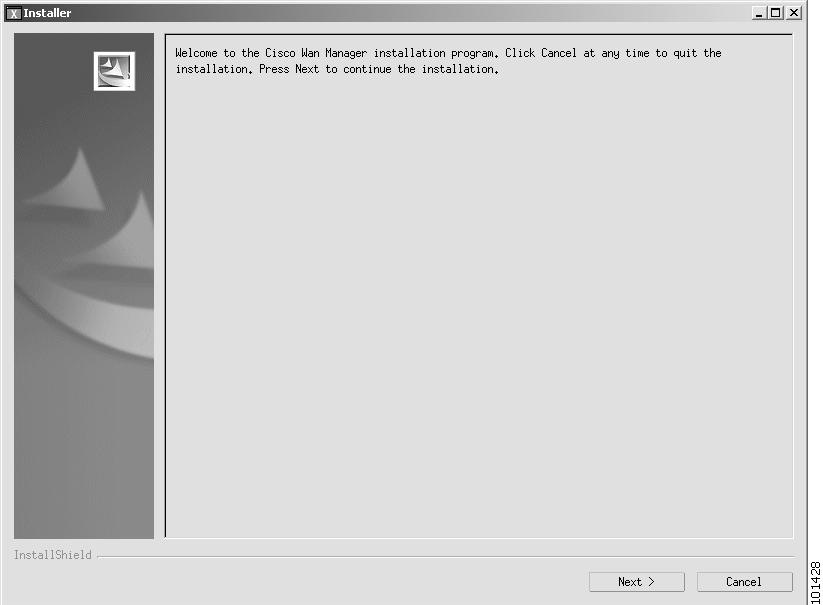
The CWM Installation Welcome window is displayed, as shown in Figure 4-1.
Figure 4-1 CWM Installation Welcome Window
Step 7
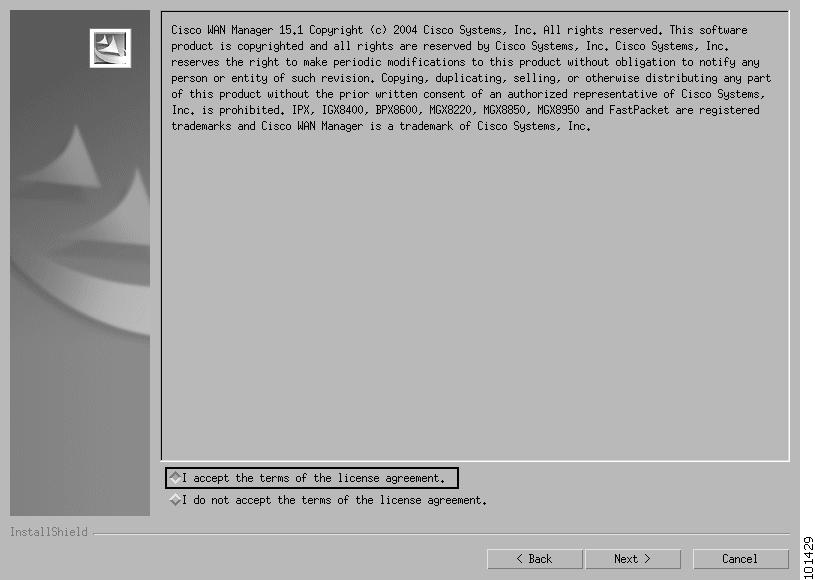
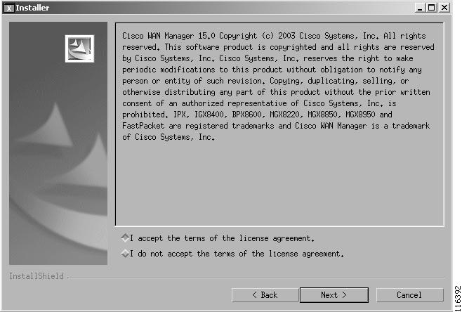
The license agreement window is displayed (see Figure 4-2).
Figure 4-2 License Agreement Window
Step 8
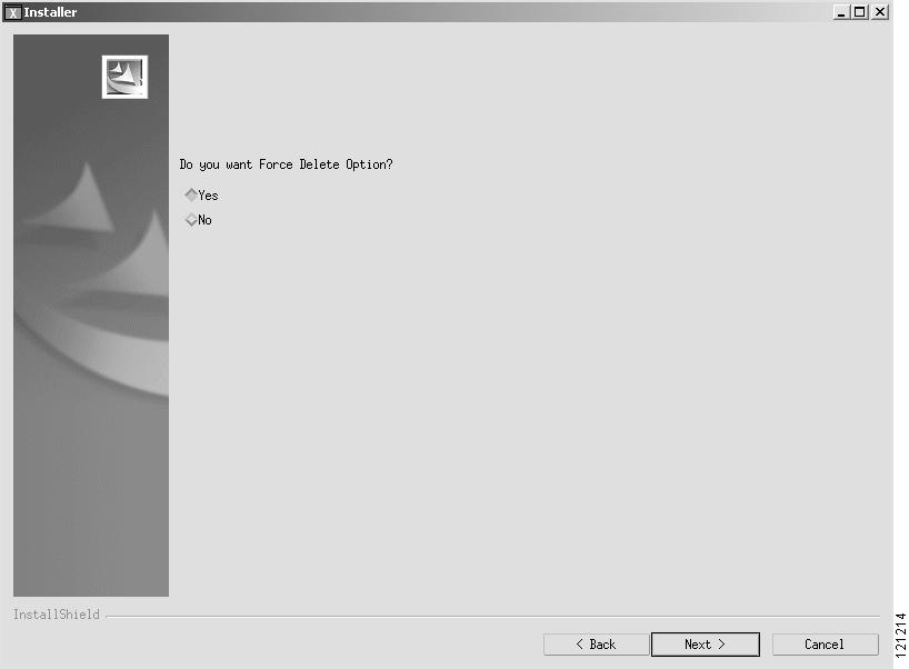
The Forced Delete Feature Selection window, Figure 4-3, is displayed. This screen prompts you to select whether or not you want to use the forced delete feature. For more information on this feature, refer to the Cisco WAN Manager User Guide, Release 15.1.
An example of the screen follows:
Figure 4-3 Forced Delete Feature Selection Window
Step 9
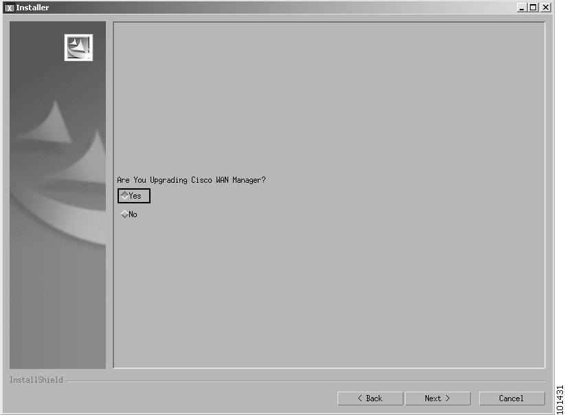
The upgrade window is displayed, as shown in Figure 4-4.
Figure 4-4 Upgrade Window
Step 10
Step 11
The CWM version window is displayed as shown in Figure 4-5.
Figure 4-5 CWM Version Window
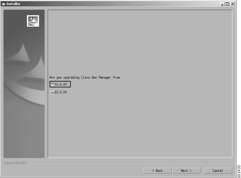
Step 12
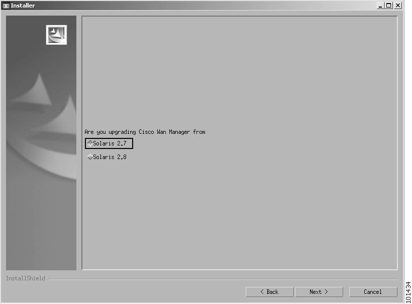
If 11.0.10 is selected, the Solaris version window is displayed as shown in Figure 4-6. Otherwise the Primary/Secondary window is displayed as shown in Figure 4-8.Figure 4-6 Solaris Version Window
Step 13
Figure 4-7 Database Path Window
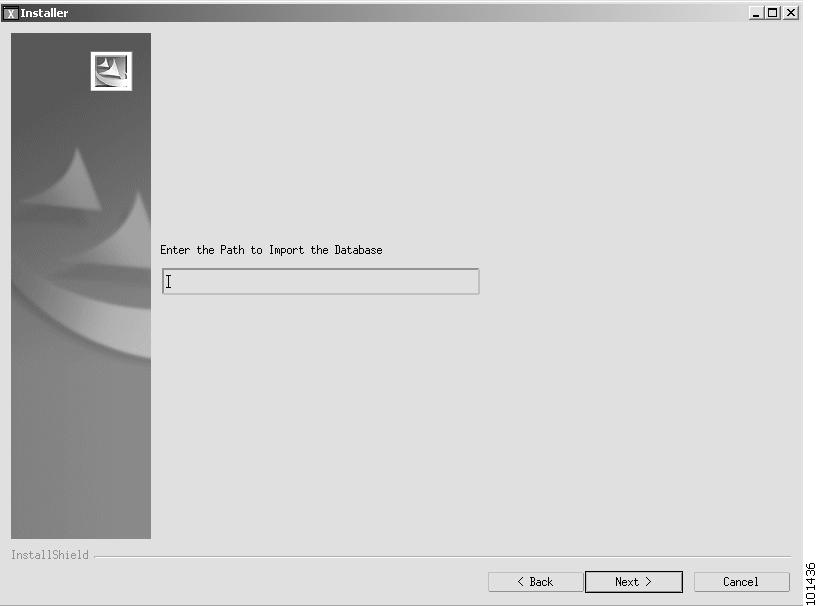
If applicable, enter the path and press Enter. The Primary/Secondary role window is displayed, as shown in Figure 4-8.Figure 4-8 Primary/Secondary Role Window
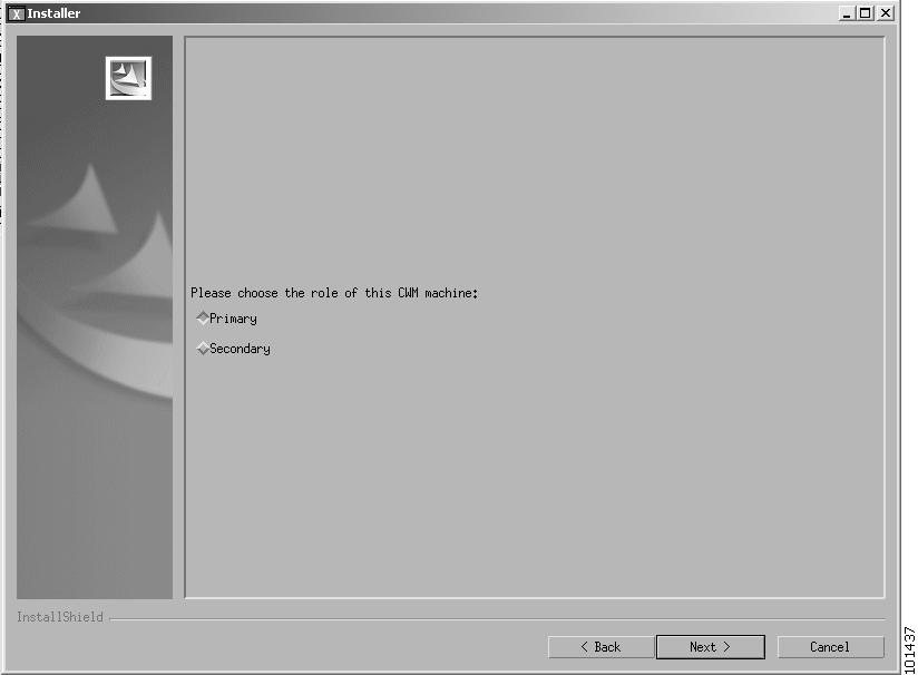
Step 14
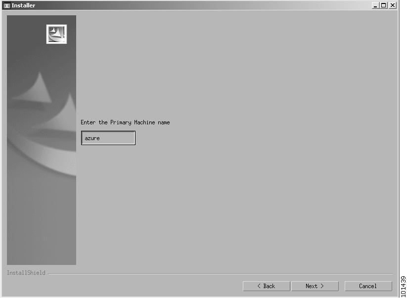
If Secondary is selected, click Next. The window is refreshed and the user is requested to enter the name of the Primary station as shown in Figure 4-9.
Figure 4-9 Primary Station Window
Step 15
Note
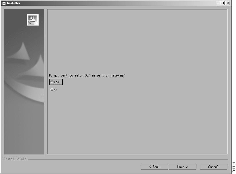
The Preserve SCM Gateway? window is displayed as shown in Figure 4-10
Figure 4-10 Preserve SCM Gateway Window
Step 16
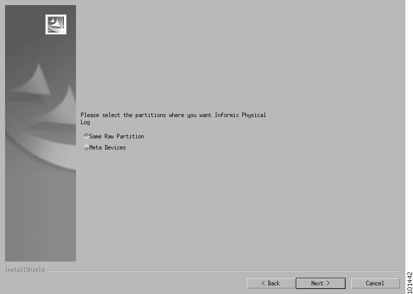
The Log Raw Partition window is displayed as shown in Figure 4-11.
Figure 4-11 Log Raw Partition Window
Step 17
Note
Step 18
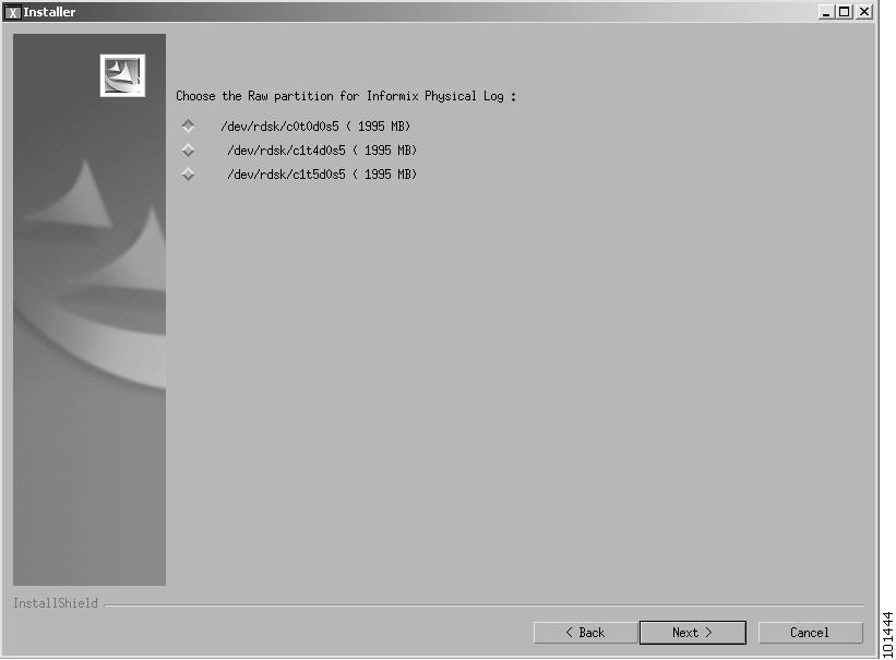
The Select the Raw Partition window is displayed, as shown in Figure 4-12.
Note
Figure 4-12 Select the Raw Partition
Step 19
Step 20
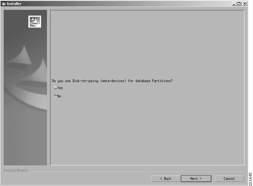
The Meta Devices window is displayed, as shown in Figure 4-13.
Figure 4-13 Meta Devices Window
Step 21
Note
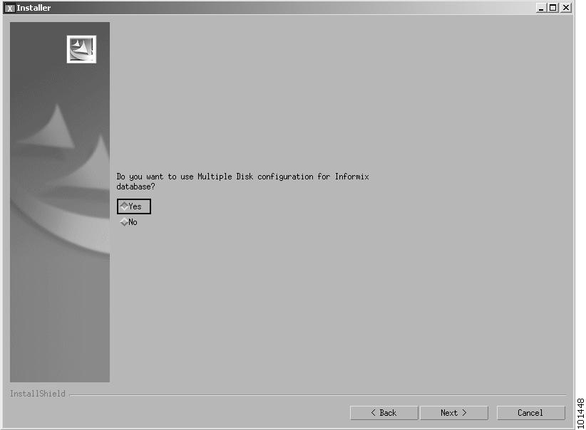
The Multiple Disk Configuration window is displayed, as shown in Figure 4-14.
Note
Figure 4-14 Multiple Disk Configuration Window
Step 22
Note
Step 23
Configuring Informix Partitions Phase
Configuring Informix partitions consists of eight different procedures of which only one needs to be performed. Which procedure the user performs depends upon the responses the user has made to the questions in the previous phase.
Select the procedure which corresponds to your previous answers to the following questions.
–
–
–
Proceed to one of the following procedures that corresponds to your answers.
In each of the procedures, the user is asked to specify details about the allocations of Informix partitions.
Note
The procedures are described in the following sequence.
1. No Meta Devices, No multiple disks, No separate raw log partition
2. No Meta Devices, No multiple disks, Yes separate raw log partition
3. No Meta Devices, Yes multiple disks, No separate raw log partition
4. No Meta Devices, Yes multiple disks, Yes separate raw log partition
5. Yes Meta Devices, No multiple disks, No separate raw log partition
6. Yes Meta Devices, No multiple disks, Yes separate raw log partition
7. Yes Meta Devices, Yes multiple disks, No separate raw log partition
8. Yes Meta Devices, Yes multiple disks, Yes separate raw log partition
1. No Meta Devices, No multiple disks, No separate raw log partition
The Select the Raw Partition for CWM Database window is displayed, as shown in Figure 4-15.
Figure 4-15 Select the Raw Partition for CWM Database Window
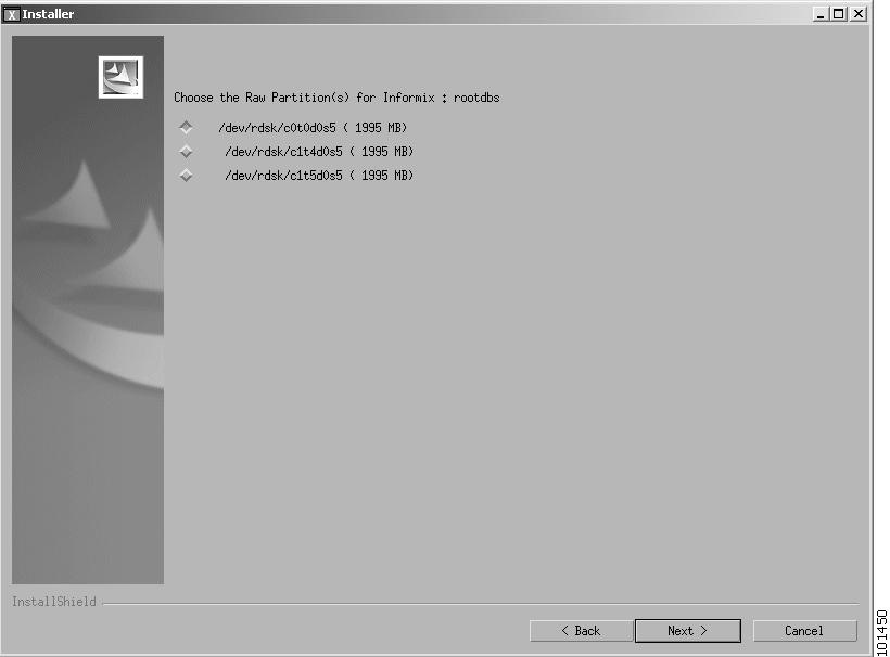
This window displays only the raw partitions available to Informix.
Step 1
Step 2
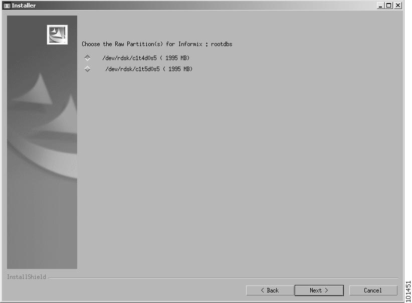
2. No Meta Devices, No multiple disks, Yes separate raw log partition
The Select the Raw Partition for CWM Database window is displayed, as shown in Figure 4-16.
Note
Figure 4-16
Select the Raw Partition for CWM Database Window
Step 1
Note
Step 2
3. No Meta Devices, Yes multiple disks, No separate raw log partition
The Select the Raw Partition for CWM Database window is displayed, as shown in Figure 4-17.
Figure 4-17 Select the Raw Partition for CWM Database Window
Step 1
Note
Rootdbs and datadbs cannot be assigned the same partitions.
If there are enough raw partitions, datadbs can be assigned multiple partitions.
Step 2
4. No Meta Devices, Yes multiple disks, Yes separate raw log partition
The Select the Raw Partition for CWM Database window is displayed, as shown in Figure 4-18.
Note
Figure 4-18
Select the Raw Partition for CWM Database Window
Step 1
Note
Step 2
5. Yes Meta Devices, No multiple disks, No separate raw log partition
The Select the Raw Partition for CWM Database window is displayed, as shown in Figure 4-19.
Figure 4-19 Select the Raw Partition for CWM Database Window
Step 1
Step 2
Step 3
6. Yes Meta Devices, No multiple disks, Yes separate raw log partition
The Select the Path for CWM Database window is displayed, as shown in Figure 4-20.
Figure 4-20 S.elect the Raw Partition for CWM Database Window
Step 1
Step 2
Step 3
7. Yes Meta Devices, Yes multiple disks, No separate raw log partition
The Select the Raw Partition for CWM Database window is displayed, as shown in Figure 4-21.
Figure 4-21 Select the Raw Partition for CWM Database Window
Step 1
Step 2
Step 3
Step 4
8. Yes Meta Devices, Yes multiple disks, Yes separate raw log partition
The Select the Raw Partition for CWM Database window is displayed, as shown in Figure 4-22.
Figure 4-22 Select the Raw Partition for CWM Database Window
Step 1
Step 2
Step 3
Completing the Installation
When the Configuring Informix Partitions phase has been completed, the CWM FTP Information Window is displayed, as shown in Figure 4-23.
Figure 4-23 CWM FTP Information Window

Step 1
Note
After entering the FTP user name and password, click Next.
The CORBA Communications Options window is displayed as shown in Figure 4-24.
Figure 4-24 CORBA Communications Options
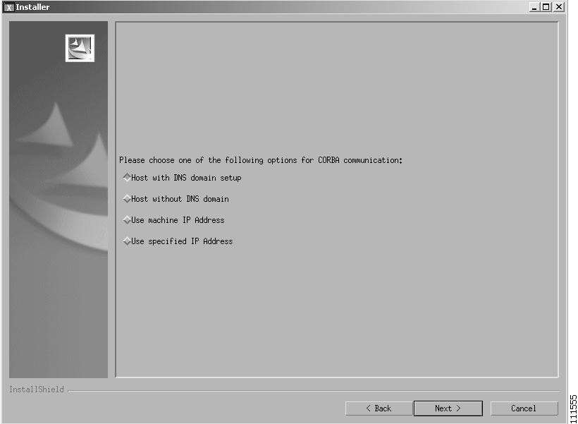
This window provides you with four choices of how the server identifies itself for CORBA (Orbix) communications. These choices are:
•
•
•
•
Select the method to use for your CWM network and click Next.
If you select "Host with DNS domain name", you are then asked to specify the domain name as shown in Figure 4-25. If you select "Use specified IP Address", you are then asked to specify the IP address as shown in Figure 4-26.
Figure 4-25 Enter the Domain Name Window
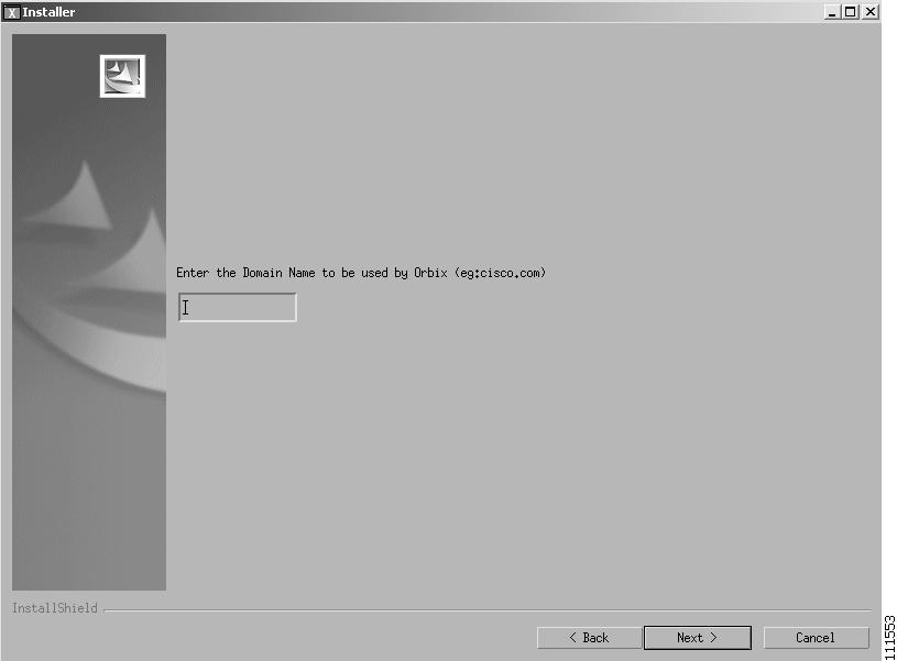
Figure 4-26 Enter IP Address Window
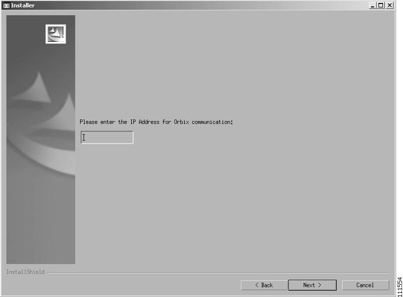
Enter the Domain Name or IP Address as appropriate and click Next.
This domain name and IP address information allows the CWM client workstations access to the database. Also ensure that the workstation and the domain is reachable. You can enter the ping command to test this.
Check for the domainname entry in the /etc/resolv.conf directory.
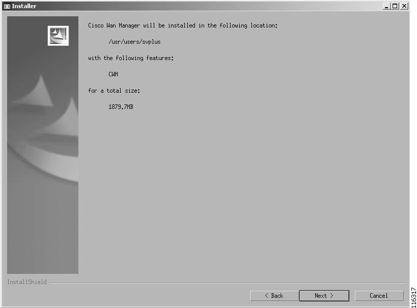
A confirmation screen prior to the actual installation of the files is displayed as shown in Figure 4-27
Figure 4-27 Installer Confirmation Window
Step 2
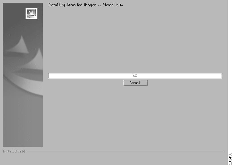
When Next is clicked, the Installation Progress Window is displayed as shown in Figure 4-28.Figure 4-28 Installation Progress Indicator
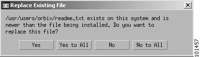
If the CWM system was installed previously, a message appears telling the user that files already exist. Permission is requested to overwrite the files with new files. This message is shown in Figure 4-29.
Figure 4-29 Copy Files Message
Step 3
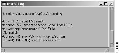
After the files are copied, an Install Log window is also displayed (see Figure 4-30). This log provides on-the-screen messages indicating events during the installation process.
Upgrading the CWM server generates the log file cwmexecinstall.Log in the /usr/users/svplus/install directory.
Figure 4-30 Install Log
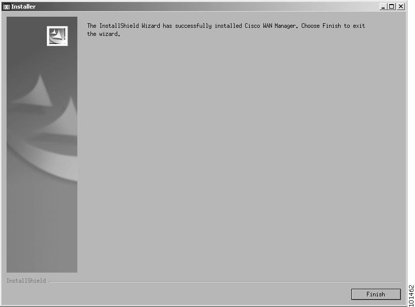
A dialog box displays informing you that the installation is complete, as shown in Figure 4-31.
Figure 4-31 Installation Complete Window
Step 4
The software installation process is completed. The Install Shield window closes.
The first time (and only the first) that CWM is installed, the system will display a message stating that the kernel has been changed. Click OK to reboot the system.
The reboot sequence aligns the cylinders of your hard disks and gracefully shuts down the Solaris operating system.
Step 5
Note
Console Mode Upgrade
If you entered Yes to run in Console Mode, the following message is displayed
You've chosen to Launch Installer in Console ModeLoading the installation classes. This may take a few minutes................................................................................................................................................................................................................................................................................................................................................................................InstallShield WizardInitializing InstallShield Wizard...Searching for Java(tm) Virtual Machine............Running InstallShield Wizard...After a few seconds the Initial Upgrade phase starts
Making Selections during Console Mode Upgrade
The Console Mode procedure consists of responding to a series of questions. The user is asked either to select an item from a list or to enter data (for example, a database path or a disk size).
Selecting an Item from a List.
When a list is displayed, each item in the list has an item number. Further, one item in the list is already selected as indicated by an X. For example:
Choose the Raw partition for Informix Physical Log :[X] 1 - /dev/rdsk/c1t0d0s7 ( 4000 MB)[ ] 2 - /dev/rdsk/c1t1d0s0 ( 2048 MB)[ ] 3 - /dev/rdsk/c1t1d0s1 ( 2048 MB)To select a choice enter its number, or 0 when you are finished [0]:The above example lists three disk partitions from which the user must select one. These items are numbered as 1, 2, and 3 and the first is already selected as indicated by [X].
The user can accept the already selected item or select another item by typing its number followed by the Enter key (The list is displayed again, with the [X] next to the selected item).
When the [X] is shown against the correct item (either in the initial display or after the user has selected another item), the user should press 0 followed by the Enter key. The following message is then displayed.
Press 1 for Next panel, 2 for Previous panel, 3 to Cancel or 4 toRedisplay [1]The user then press 1, 2, 3, or 4 (as appropriate) followed by the Enter key. Normally this will be the 1 key to progress to next step in the upgrade process.
Entering Data
When requested enter the data and press the Enter key. If you want to change the entered data, press 1 and the enter key and then start over. When the enter data are correct, press 0 and the Enter key.
Initial Upgrade Phase
Step 1
-------------------------------------------------------------------------------Welcome to the Cisco Wan Manager installation program. Click Cancelat any time to quit the installation. Press Next to continue the installation.Press 1 for Next panel, 3 to Cancel or 4 to Redisplay [1]-------------------------------------------------------------------------------Press 1 then Enter to display the next message
Step 2
-------------------------------------------------------------------------------Cisco Wan Manager 15.1.0 Copyright (c) 2004 Cisco Systems, Inc. Allrights reserved. This software product is copyrighted and all rights arereserved by Cisco Systems, Inc. Cisco Systems, Inc. reserves the right to makeperiodic modifications to this product without obligation to notify any personor entity of such revision. Copying, duplicating, selling, or otherwisedistributing any part of this product without the prior written consent of anauthorized representative of Cisco Systems, Inc. is prohibited. IPX, IGX8400,BPX8600, MGX8220, MGX8850, MGX8950 and FastPacket are registered trademarksand Cisco WAN Manager is a trademark of Cisco Systems, Inc.Please choose from the following options:[X] 1 - I accept the terms of the license agreement.[ ] 2 - I do not accept the terms of the license agreement.To select a choice enter its number, or 0 when you are finished [0]:Press 1 for Next panel, 2 for Previous panel, 3 to Cancel or 4 toRedisplay [1]-------------------------------------------------------------------------------a.
b.
Step 3
-------------------------------------------------------------------------------Are You Upgrading Cisco WAN Manager?[ ] 1 - Yes[X] 2 - NoTo select a choice enter its number, or 0 when you are finished [0]:Press 1 for Next panel, 2 for Previous panel, 3 to Cancel or 4 toRedisplay [1]-------------------------------------------------------------------------------a.
b.
Step 4
Are you upgrading Cisco Wan Manager from[X] 1 - 11.0.10[ ] 2 - 12.0.00To select a choice enter its number, or 0 when you are finished [0]: 0Press 1 for Next panel, 2 for Previous panel, 3 to Cancel or 4 toRedisplay [1] 1-------------------------------------------------------------------------------Indicate which version of CWM is being upgraded.
a.
b.
Step 5
Are you upgrading Cisco Wan Manager from[ ] 1 - Solaris 2.7[X] 2 - Solaris 2.8To select a choice enter its number, or 0 when you are finished [0]: 0Press 1 for Next panel, 2 for Previous panel, 3 to Cancel or 4 toRedisplay [1] 1-------------------------------------------------------------------------------Indicate the version of Solaris that is being upgraded.
a.
b.
Step 6
-------------------------------------------------------------------------------Enter the Path to Import the Database[] /usr/users/svplus/etcPress 1 for Next panel, 2 for Previous panel, 3 to Cancel or 4 toRedisplay [1]Upgrading from 11.0.10Press Enter-------------------------------------------------------------------------------Please choose the role of this CWM machine:
[X] 1 - Primary[ ] 2 - SecondaryTo select a choice enter its number, or 0 when you are finished [0]:Press 1 for Next panel, 2 for Previous panel, 3 to Cancel or 4 toRedisplay [1]-------------------------------------------------------------------------------Do you want to setup SCM as part of gateway?[ ] 1 - Yes[X] 2 - NoTo select a choice enter its number, or 0 when you are finished [0]:Press 1 for Next panel, 2 for Previous panel, 3 to Cancel or 4 toRedisplay [1]-------------------------------------------------------------------------------Step 7
-------------------------------------------------------------------------------Do you want Informix Physical Log on a separate Raw Partition?[ ] 1 - Yes[X] 2 - NoTo select a choice enter its number, or 0 when you are finished [0]:Press 1 for Next panel, 2 for Previous panel, 3 to Cancel or 4 toRedisplay [1]-------------------------------------------------------------------------------a.
b.
c.
Step 8
Note
-------------------------------------------------------------------------------Choose the Raw partition for Informix Physical Log :[X] 1 - /dev/rdsk/c1t0d0s7 ( 4000 MB)[ ] 2 - /dev/rdsk/c1t1d0s0 ( 2048 MB)[ ] 3 - /dev/rdsk/c1t1d0s1 ( 2048 MB)[ ] 4 - /dev/rdsk/c1t1d0s3 ( 2048 MB)To select a choice enter its number, or 0 when you are finished [0]:Press 1 for Next panel, 2 for Previous panel, 3 to Cancel or 4 toRedisplay [1]-------------------------------------------------------------------------------This panel displays all the raw partitions that are available for the Informix Physical Log.
a.
b.
Step 9
Note
-------------------------------------------------------------------------------Do you use Disk-stripping (meta-devices) for database Partitions?[ ] 1 - Yes[X] 2 - NoTo select a choice enter its number, or 0 when you are finished [0]:Press 1 for Next panel, 2 for Previous panel, 3 to Cancel or 4 toRedisplay [1]-------------------------------------------------------------------------------a.
b.
c.
Step 10
Note
-------------------------------------------------------------------------------Do you want to use Multiple Disk configuration for Informix database?[ ] 1 - Yes[X] 2 - NoTo select a choice enter its number, or 0 when you are finished [0]:Press 1 for Next panel, 2 for Previous panel, 3 to Cancel or 4 toRedisplay [1]-------------------------------------------------------------------------------a.
b.
c.
Configuring Informix Partitions Phase
Configuring Informix partitions consists of eight different procedures of which only one needs to be performed. Which procedure the user performs depends upon the responses the user has made to the questions in the previous phase.
Select the procedure which corresponds to your previous answers to the following questions.
–
–
–
Proceed to one of the following procedures that corresponds to your answers.
In each of the procedures, the user is asked to specify details about the allocations of Informix partitions.
Note
The procedures are described in the following sequence.
1. No Meta Devices. No Multiple Disks, No Separate Raw Log Partition
2. No Meta Devices. No Multiple Disks, Yes Separate Raw Log Partition
3. No Meta Devices. Yes Multiple Disks. No Separate Raw log partition
4. No Meta Devices. Yes Multiple Disks. Yes Separate Raw log partition
5. Yes Meta Devices. No Multiple Disks. No Separate Raw Log Partition
6. Yes Meta Devices. No Multiple Disks. Yes Separate Raw Log Partition
7. Yes Meta Devices. Yes Multiple Disks. No Separate Log Partition
8. Yes Meta Devices. Yes Multiple Disks. Yes Separate Log Partition
1. No Meta Devices. No Multiple Disks, No Separate Raw Log Partition
The following panel is displayed:.
-------------------------------------------------------------------------------Choose the Raw Partition(s) for Informix : rootdbs[X] 1 - /dev/rdsk/c1t1d0s0 ( 2048 MB)[ ] 2 - /dev/rdsk/c1t1d0s1 ( 2048 MB)[ ] 3 - /dev/rdsk/c1t1d0s3 ( 2048 MB)To select a choice enter its number, or 0 when you are finished [0]:Press 1 for Next panel, 2 for Previous panel, 3 to Cancel or 4 toRedisplay [1]-------------------------------------------------------------------------------This window displays only the raw partitions available to Informix.
Step 1
Step 2
2. No Meta Devices. No Multiple Disks, Yes Separate Raw Log Partition
The following panel is displayed:.
-------------------------------------------------------------------------------Choose the Raw Partition(s) for Informix : rootdbs[X] 1 - /dev/rdsk/c1t1d0s0 ( 2048 MB)[ ] 2 - /dev/rdsk/c1t1d0s1 ( 2048 MB)To select a choice enter its number, or 0 when you are finished [0]:Press 1 for Next panel, 2 for Previous panel, 3 to Cancel or 4 toRedisplay [1]-------------------------------------------------------------------------------This window displays only the raw partitions available to Informix. Notice that the separate partition previously selected for the Informix physical log is no longer available and is not displayed.
Step 1
Step 2
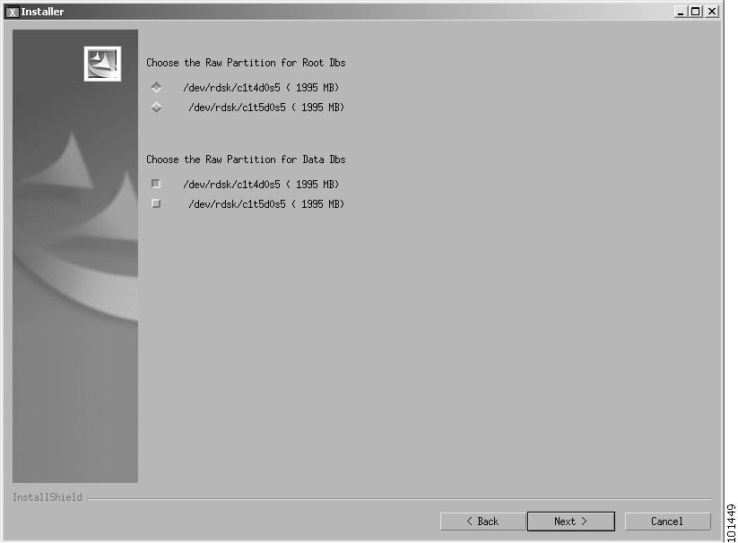
3. No Meta Devices. Yes Multiple Disks. No Separate Raw log partition
The following panel is displayed:
-------------------------------------------------------------------------------Choose the Raw Partition for Root Dbs[X] 1 - /dev/rdsk/c1t0d0s7 ( 4000 MB)[ ] 2 - /dev/rdsk/c1t1d0s0 ( 2048 MB)[ ] 3 - /dev/rdsk/c1t1d0s1 ( 2048 MB)To select a choice enter its number, or 0 when you are finished [0]: 5
Step 1
The following panel is displayed:.[ ] 2 - /dev/rdsk/c1t1d0s0 ( 2048 MB)[ ] 3 - /dev/rdsk/c1t1d0s1 ( 2048 MB)[ ] 4 - /dev/rdsk/c1t1d0s3 ( 2048 MB)[X] 5 - /dev/rdsk/c1t1d0s4 ( 2048 MB)To select a choice enter its number, or 0 when you are finished [0]:Press 1 for Next panel, 2 for Previous panel, 3 to Cancel or 4 to Redisplay [1]-------------------------------------------------------------------------------Step 2
Step 3
4. No Meta Devices. Yes Multiple Disks. Yes Separate Raw log partition
The following panel is displayed:
-------------------------------------------------------------------------------Choose the Raw Partition for Root Dbs[X] 1 - /dev/rdsk/c1t0d0s7 ( 4000 MB)[ ] 2 - /dev/rdsk/c1t1d0s0 ( 2048 MB)[ ] 3 - /dev/rdsk/c1t1d0s1 ( 2048 MB)[ ] 4 - /dev/rdsk/c1t1d0s3 ( 2048 MB)[ ] 5 - /dev/rdsk/c1t1d0s4 ( 2048 MB)To select a choice enter its number, or 0 when you are finished [0]:
Step 1
Press 1 then Enter, The following panel is displayed:Choose the Raw Partition for Data Dbs[ ] 2 - /dev/rdsk/c1t1d0s0 ( 2048 MB)[ ] 3 - /dev/rdsk/c1t1d0s1 ( 2048 MB)[ ] 4 - /dev/rdsk/c1t1d0s3 ( 2048 MB)[X] 5 - /dev/rdsk/c1t1d0s4 ( 2048 MB)To select a choice enter its number, or 0 when you are finished [0]:Press 1 for Next panel, 2 for Previous panel, 3 to Cancel or 4 to Redisplay [1]-------------------------------------------------------------------------------Step 2
Step 3
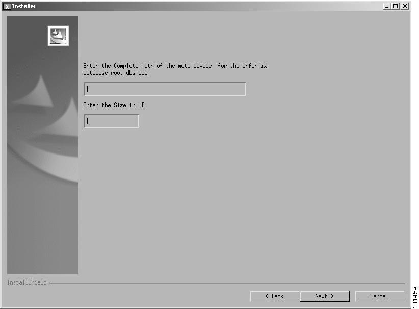
5. Yes Meta Devices. No Multiple Disks. No Separate Raw Log Partition
The following panel is displayed:
-------------------------------------------------------------------------------Enter the Complete path of the meta device for the informix database rootdbspace[]
Step 1
The following panel is displayed:Enter the Size in MB[]Press 1 for Next panel, 2 for Previous panel, 3 to Cancel or 4 toRedisplay [1]-------------------------------------------------------------------------------Step 2
Step 3
6. Yes Meta Devices. No Multiple Disks. Yes Separate Raw Log Partition
The following panel is displayed:
-------------------------------------------------------------------------------Enter the Complete path of the meta device for the informix database rootdbspace[]
Step 1
The following panel is displayed:Enter the Size in MB[]Press 1 for Next panel, 2 for Previous panel, 3 to Cancel or 4 toRedisplay [1]-------------------------------------------------------------------------------Step 2
Step 3
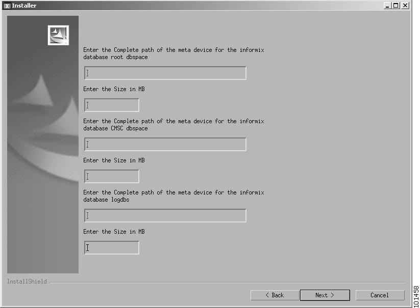
7. Yes Meta Devices. Yes Multiple Disks. No Separate Log Partition
The following panel is displayed:
-------------------------------------------------------------------------------Enter the Complete path of the meta device for the informix database rootdbspace[]
Step 1
The following panel is displayed:Enter the Size in MB[]Step 2
.Enter the Complete path of the meta device for the informix database CWMdbspace[]Step 3
The following panel is displayed:Enter the Size in MB[]Step 4
The following panel is displayed:.[]Enter the Complete path of the meta device for the informix database logdbs[]Enter the Size in MB[]Step 5
The following panel is displayed:Enter the Size in MB[]Press 1 for Next panel, 2 for Previous panel, 3 to Cancel or 4 toRedisplay [1]Step 6
Step 7
8. Yes Meta Devices. Yes Multiple Disks. Yes Separate Log Partition
The following panel is displayed:
-------------------------------------------------------------------------------Enter the Complete path of the meta device for the informix database rootdbspace[]
Step 1
The following panel is displayed:Enter the Size in MB[]Step 2
.Enter the Complete path of the meta device for the informix database CWMdbspace[]Step 3
The following panel is displayed:Enter the Size in MB[]Step 4
The following panel is displayed:.[]Enter the Complete path of the meta device for the informix database logdbs[]Enter the Size in MB[]Step 5
The following panel is displayed:Enter the Size in MB[]Press 1 for Next panel, 2 for Previous panel, 3 to Cancel or 4 toRedisplay [1]-------------------------------------------------------------------------------Step 6
Step 7
Completing the Installation
When one of the eight Informix partition phase procedures has been completed, the FTP Information panel is displayed automatically.
-------------------------------------------------------------------------------FTP User name[svplus]FTP Password:ReEnter the Password: Press 1 for Next panel, 2 for Previous panel, 3 to Cancel or 4 toRedisplay [1]-------------------------------------------------------------------------------
Step 1
a.
b.
c.
Note
d.
Step 2
-------------------------------------------------------------------------------Please choose one of the following options for CORBA communication:[X] 1 - Host with DNS domain setup[ ] 2 - Host without DNS domain[ ] 3 - Use machine IP Address[ ] 4 - Use specified IP AddressTo select a choice enter its number, or 0 when you are finished [0]:This window provides the user with four choices of how the server identifies itself for CORBA (Orbix) communications. These choices are:
•
•
•
•
Perform the following sub-steps.
a.
b.
c.
-------------------------------------------------------------------------------Enter the Domain Name to be used by Orbix (eg:cisco.com)[]Press 1 for Next panel, 2 for Previous panel, 3 to Cancel or 4 toRedisplay [1] 2-------------------------------------------------------------------------------Enter the Domain Name and press the Return key, Press 1 for the next panel.
d.
-------------------------------------------------------------------------------Please enter the IP Address for Orbix communication:[172.29.52.25]Press 1 for Next panel, 2 for Previous panel, 3 to Cancel or 4 toRedisplay [1] 1-------------------------------------------------------------------------------Enter the IP Address and press the Return key, Press 1 for the next panel.
The Installation Preview panel is displayed.
-------------------------------------------------------------------------------Cisco Wan Manager will be installed in the following location:/usr/users/svpluswith the following features:CWMfor a total size:1743.9MBPress 1 for Next panel, 2 for Previous panel, 3 to Cancel or 4 toRedisplay [1]-------------------------------------------------------------------------------Step 3
a.
b.
The Installation Progress panel is displayed.
-------------------------------------------------------------------------------Running in Console Mode. Do tail -f in a separate window on log file for status.Log file is /usr/users/svplus/install/cwmexecInstall.LogInstalling Cisco Wan Manager ... Please wait.|-----------|-----------|-----------|------------|0% 25% 50% 75% 100%|||||||||||||||||||||||||||||||||||||||||||||||||Committing changes to the Solaris Product Registry.|.........DONECreating uninstaller...-------------------------------------------------------------------------------The progress bar indicates the progress of the installation. When the installation is complete, the Installation Complete is displayed.
-------------------------------------------------------------------------------The InstallShield Wizard has successfully installed Cisco Wan Manager. Choose Finish to exit the wizard.Press 3 to Finish or 4 to Redisplay [3]-------------------------------------------------------------------------------Step 4
Installing RtmProxy
RtmProxy is a software module that allows the user to receive traps from a standalone statistics manager (SSM) machine when there is no Service Agent installed on the CWM Server.
Note
If RtmProxy is installed in a CWM Server and later you want to install the CWM Service Agent, uninstall RtmProxy first (see Chapter 9 for details).
Selecting the Installation Mode
To install the RtmProxy software, perform the following steps:
Step 1
Note
If the CWM server is a Netra 20 or other rackmount system, use another Sun workstation or PC as a console and log in remotely using telnet).
Step 2
CD-ROM Number 1 into the CD-ROM drive of the CWM workstation.Step 3
# cd /cdrom/cdrom0# lsStep 4
InstallRTMProxy.shfile.Step 5
# ./InstallRTMProxy.shThe following message is displayed.
Console Mode Option is recommended when you cannot connect to X Serverfrom current terminal (See if you can open an xterm to check!)Do you Want to Launch Installer in Console Mode? (Yes / No): [No]:yStep 6
Respond Yes to continue the installation using Console Mode Install.
Note
Installshield GUI Installation
The installation classes are loaded: this process takes several minutes.
The RtmProxy Installation Welcome window is displayed, as shown in Figure 4-32.
Figure 4-32 RTM Proxy Installation Welcome Window
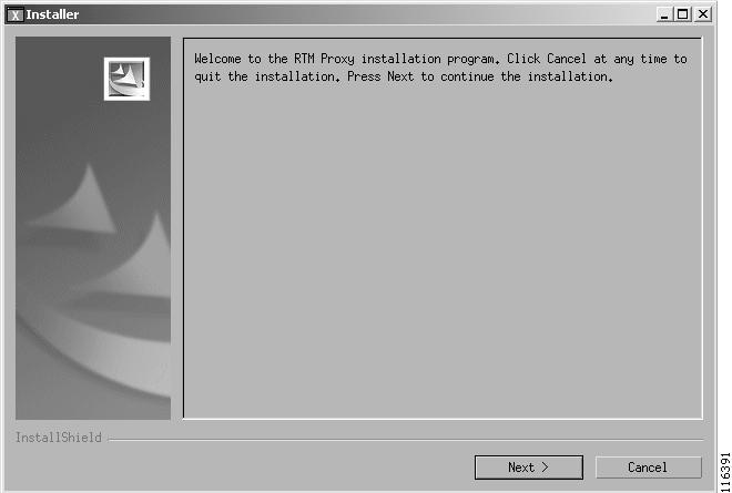
Step 1
The License Agreement window, Figure 4-33, is displayed.
Figure 4-33 License Agreement Window
Step 2
A confirmation screen prior to the actual installation of the files is displayed as shown in Figure 4-34.
Figure 4-34 Installer Confirmation Window
Step 3
When Next is clicked, the Installation Progress Window is displayed as shown in Figure 4-35.Figure 4-35 Installation Progress Indicator
After the files are copied, an Install Log window is also displayed. This log provides on-the-screen messages indicating events during the installation process.
A dialog box displays informing you that the installation is complete, as shown in Figure 4-36.
Figure 4-36 Installation Complete Window
Step 4
The software installation process is completed. The Install Shield window closes.
Console Mode Installation
If you enter Yes to run in Console Mode, the following panel is displayed
You've chosen to Launch Installer in Console ModeLoading the installation classes. This may take a few minutes................................................................................................................................................................................................................................................................................................................................................................................InstallShield WizardInitializing InstallShield Wizard...Searching for Java(tm) Virtual Machine............Running InstallShield Wizard...After a few seconds the Initial Installation phase starts
Making Selections during Console Mode Upgrade
The Console Mode procedure consists of responding to a series of questions. The user is asked either to select an item from a list or to enter data (for example, a database path or a disk size).
Selecting an Item from a List.
When a list is displayed, each item in the list has an item number. One item in the list is already selected as indicated by an X. For example:
Choose from the following options:[X] 1 - I accept the terms of the license agreement.[ ] 2 - I do not accept the terms of the license agreement.To select a choice enter its number, or 0 when you are finished [0]: 0The above example lists two options from which the user must select one. These items are numbered as 1 and 2 and the first is already selected as indicated by [X].
The user can accept the already selected item or select another item by typing its number followed by the Enter key (in which case the list is displayed again but with the [X] against the selected item).
When the [X] is shown against the correct item (either in the initial display or after the user has selected another item), the user should press 0 followed by the Enter key. The following message is then displayed.
Press 1 for Next panel, 2 for Previous panel, 3 to Cancel or 4 toRedisplay [1]The user then press 1, 2, 3, or 4 (as appropriate) followed by the Enter key. Normally this will be the 1 key to progress to next step in the upgrade process.
Entering Data
When requested, enter the data and press the Enter key. If you want to change the entered data, press 1 and the Enter key and then start over. When the enter data are correct, press 0 and the Enter key.
Installation Phase
Step 1
-------------------------------------------------------------------------------Welcome to the RTM Proxy installation program. Click Cancelat any time to quit the installation. Press Next to continue the installation.Press 1 for Next panel, 3 to Cancel or 4 to Redisplay [1]-------------------------------------------------------------------------------Press 1 then Enter to display the next message
Step 2
-------------------------------------------------------------------------------Cisco WAN Manager 15.1.0 Copyright (c) 2004 Cisco Systems, Inc. All rightsreserved. This software product is copyrighted and all rights are reserved byCisco Systems, Inc. Cisco Systems, Inc. reserves the right to make periodicmodifications to this product without obligation to notify any person orentity of such revision. Copying, duplicating, selling, or otherwisedistributing any part of this product without the prior written consent of anauthorized representative of Cisco Systems, Inc. is prohibited. IPX, IGX8400,BPX8600, MGX8220, MGX8850, MGX8950 and FastPacket are registered trademarksand Cisco WAN Manager is a trademark of Cisco Systems, Inc.Please choose from the following options:[X] 1 - I accept the terms of the license agreement.[ ] 2 - I do not accept the terms of the license agreement.To select a choice enter its number, or 0 when you are finished [0]: 0Press 1 for Next panel, 2 for Previous panel, 3 to Cancel or 4 toRedisplay [1] 1-------------------------------------------------------------------------------a.
b.
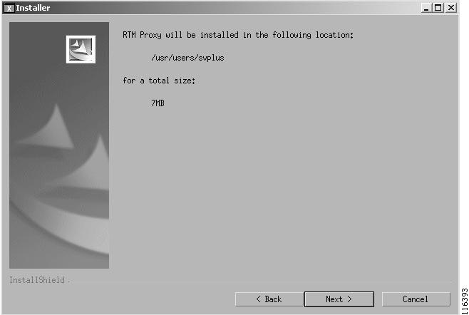
Step 3
RTM Proxy will be installed in the following location:/usr/users/svplusfor a total size:7MBPress 1 for Next panel, 2 for Previous panel, 3 to Cancel or 4 toRedisplay [1] 1Press 1 to start the installation or, if the information is not correct, press 2 to go back.
The following message is displayed.
Running in Console Mode...Configuration status can be checked by executing 'tail -f /usr/users/svplus/install/RTMexecinstall.Log'Installing RTM Proxy... Please wait.|-----------|-----------|-----------|------------|0% 25% 50% 75% 100%|||||||||||||||||||||||||||||||||||||||||||||The progress bar is updated during the installation. When finished, the following message is displayed.
....DONECreating uninstaller...-------------------------------------------------------------------------------The InstallShield Wizard has successfully installed RTM Proxy. Choose Finishto exit the wizard.Press 3 to Finish or 4 to Redisplay [3] 3Step 4
Upgrading to CWM 15.1 from Solaris 8 to Solaris 9 with Multiple CWM Gateways
When upgrading from a network in which there are multiple CWM gateways, a special sequence of steps needs to be followed. This procedure ensures that, at all times, the network management functions are not interrupted, that there is one and only one primary CWM in a CWM domain, and that the integrity of the network configuration and user data files is maintained.
Initial Conditions before Upgrade
Consider an example CWM network system running on Solaris 8 workstations. The network has three Release 12 or Release 15 CWM gateways (named A, B, and C), all in the same domain. The gateways consist of one primary and two secondaries. All gateways are up and running and all are synced with the network configuration and user data.
Note
In CWM the first station to be started is automatically assigned the role of primary station. The second station to be started becomes a secondary workstation with priority 1. Subsequent stations become secondary stations with priorities of 2, 3, and so on. To ensure such a primary/secondary arrangement, the DomainGatewayList field in the CWMGateway.conf file for all three CWM workstations must list all CWM gateways.
In the example shown in Figure 4-37, CWMA workstation is primary and workstations CWMB and CWMC are secondary with priorities of 1 and 2 respectively. The CWMGateway.conf field for all three gateways contains the following entry:
DomainGatewayList CWMA CWMB CWMCFigure 4-37 Initial State of CWM Gateways
CWMA-Sol 8
Primary
DomainGatewayList = A, B, CCWMB-Sol 8
Secondary Pri 1
DomainGatewayList = A, B, CCWMC-Sol 8
Secondary Pri 2
DomainGatewayList = A, B, C
Upgrade Procedure
The following steps upgrade the workstations, one by one, to Release 15.1.
Step 1
This action causes CWMB to assume the role of primary and CWMC assumes the role of secondary priority 1.
Step 2
a.
b.
c.
d.
Step 3
CWMA starts as primary but in a different gateway domain.
The new states of the three-CWM workstations are shown in Figure 4-38.
Figure 4-38 State of CWM Gateways after Step 3
CWMA-Sol 9
Primary
DomainGatewayList = ACWMB- Sol 8
Primary
DomainGatewayList = A, B, CCWMC-Sol 8
Secondary Pri 1
DomainGatewayList = A, B, C
Step 4
This action causes CWMC to assume the role of primary.
Step 5
a.
b.
c.
d.
When requested, use the Primary/Secondary select window to select CWMB as secondary and CWMA as primary.
Step 6
CWMB starts as secondary priority 1 in the same domain as CWMA.
The new states of the three-CWM workstations are shown in Figure 4-39.
Figure 4-39 State of CWM Gateways after Step 6
CWMA-Sol 9
Primary
DomainGatewayList = ACWMB-Sol 9
Secondary Pri 1
DomainGatewayList = A, BCWMC-Sol 8
Primary
DomainGatewayList = A, B, C
Step 7
Step 8
a.
b.
c.
d.
When requested, use the Primary/Secondary select window to select CWMC as secondary and CWMA as primary.
Step 9
CWMC starts as secondary priority 2 in the same domain as CWMA and CWMB.
The new states of the three-CWM workstations are shown in Figure 4-40.
Figure 4-40 State of CWM Gateways after Step 9
CWMA 15.1-Sol 9
Primary
DomainGatewayList = ACWMB 15.1-Sol 9
Secondary Pri 1
DomainGatewayList = A, BCWMC 15.1-Sol 9
Secondary Pri 2
DomainGatewayList = A, C
Step 10
The user must now update the DomainGatewayList in the CWMGateway.conf file for all three gateways to include CWMA, CWMB, and CWMC. In this way the gateways will be part of the same gateway domain when their cores are restarted.
Upgrading to CWM 15.1 Solaris 8 from CWM 12 or 15 Solaris 8 with Multiple CWM Gateways
Use the procedure above except that the following tasks at each step are omitted.
a.
b.
c.
The only task required at each step is that of upgrading the CWM software.
Post Installation Tasks
After the CWM installation is complete the following configuration tasks should be completed.
If you haven't already done so, eject the CWM CD-ROM by entering the eject command in the terminal window.
Checking the CWM Server File System
At the CWM workstation log in as user root, and examine the following files.
•
•
•
•
•
•
•
•
•
•
Note
/etc/hosts
Examine the /etc/hosts file and check that the file contains a nodename and IP address for all nodes. The IP address should be one that CWM can use for network discovery (see the following paragraphs).
To view the /etc/hosts file, enter the following command:
host% more /etc/hostsIf the host file needs to be modified, use vi or some other editor to enter items into the file.
MGX Nodes
For each node:
Enter the IP address and its nodename.
as specified in the node's Ipifconfig command and option 8 of the node's cnfndparms command.
Note
Option 8 in the node's cnfndparms CLI command is then used to specify which of these two addresses is to be used for CWM and it is this IP address that should be used in the hosts file.
The current setting of option 8 can be displayed using the dspndparms command.
For more details of these commands, see Cisco MGX 8850 (PXM1E/PXM45), Cisco MGX 8950, and Cisco MGX 8830 Command Reference, Release 5.1.
Example host file entry:
172.70.209.9 mgx4BPX Nodes
For each node:
Enter the node's IP address and the node name.
Example:
192.0.0.8 bpx1Example Hosts File
A hosts file might look like the following example:
# MGX Rel 1, 2.0, up to 2.1.60 nodes172.70.207.9 mgx1192.0.0.9 mgx1-l172.70.207.6 mgx2192.0.0.6 mgx2-l172.70.207.4 mgx3192.0.0.4 mgx3-l##MGX nodes172.70.209.9 mgx4172.70.209.8 mgx5172.70.209.7 mgx6172.70.209.6 mgx7##BPX nodes192.0.0.8 bpx1192.0.0.9 bpx2192.0.0.10 bpx3/etc/netmasks
Examine the /etc/netmasks file for all subnet and netmask entries. To view the /etc/netmasks file, enter the following command:
host% more /etc/netmasksAn example of a netmasks entry is:
172.29.52.0 225.225.225.0
This display indicates a network number and a network mask of 225.225.225.0 which is a commonly used value.
The network mask is installation dependent (check with your network administrator). Use vi or some other editor to change the value if necessary.
/etc/rc2.d/S72inetsvc
Examine the /etc/rc2.d/S72inetsvc file to ensure that the IP relay address points to the gateway node. To view the /etc/rc2.d/S72inetsvc file, enter the following command:
host% more /etc/rc2.d/S72inetsvcUse vi or some other editor to open the S72inetsvc file and find the following line:
/usr/sbin/route -n add -interface "224.0/4" "$mcastif" >/dev/null)&Add the following line directly below that line
/usr/sbin/route add net 10.10.10.0 209.165.200.225  1  (use your site's valid IP addresses
and netmask)
/system
Change directory to /system and enter the ls command. Check to see that all required HPOV PSOV_XXXXX patches have been installed.
# cd /system
# ls
etc/system
Check to see that the CWM installation process added the semaphores required for Solaris and HP OpenView operability.
Verify that the following line exists in this file:
(set semsys:seminfo_semmsl=30).
If this line does not exist or is incorrect, make the necessary correction.
forceload: sys/shmsysforceload: sys/semsysset semsys:seminfo_semaem=16384set semsys:seminfo_semmap=66set semsys:seminfo_semmni=4096set semsys:seminfo_semmns=4096set semsys:seminfo_semmnu=4096set semsys:seminfo_semume=64set semsys:seminfo_semvmx=32767set semsys:seminfo_semmsl=30set shmsys:shminfo_shmmax=268435456set shmsys:shminfo_shmmin=100set shmsys:shminfo_shmmni=100set shmsys:shminfo_shmseg=100/etc/defaultrouter
Examine the /etc/defaultrouter file. To view the /etc/defaultrouter file, enter the following command:
host% more /etc/defaultrouter
Note
If the router IP address is not currently in the file, use the vi Editor to add a line containing the IP address of the default router to which the CWM workstation is attached.
Reboot the Workstation
After completing the configuration, reboot the workstation.
/svplus/config/network.conf file
The network.conf file is located in the /usr/users/svplus/config/ directory. It is used to specify the network(s) to be discovered and managed by CWM. Basically, this file describes the routing protocol, the gateway address to the network, and whether in-band or out-of-band management is to be used.
The format of the file depends upon the type of network of which there are four as follows.
•
•
•
•
To view the /usr/users/svplus/config/network.conf file, enter the following command:
host% more /usr/users/svplus/config/network.confNetwork.conf File for AutoRoute Networks (BPX/IGX)
For AutoRoute BPX and IGX networks using in-band management the file has the following format:
NETWORK:Network1 (a name for CWM to identify the network)GATEWAYS:sj123456 (the name or IP address of the gateway to the network)DISCOVERY PROTOCOL:AUTOROUTE (the discovery protocol, in this case always AUTOROUTE)IP REACHABILITY FLAG:NWIP_OFF (specifies in-band or out-of-band management)OPTIONAL:"TIMEOUT = 7, RETRANSMIT = 6, THROTTLE = 0, ACKNOWLEDGE = 30, BLOCKSIZE = 1024"(the optional field is used to specify parameters if the desired value is different from the default value, see Table 4-2)Check that the mnemonic of the gateway node is correct. Also, for BPX and IGX, check that the IP Reachability Flag is correct as shown in Table 4-1.
Note
Table 4-2 provides a list of the optional parameters in the network.conf file.
Note
Sample Network 1: Discover an AutoRoute Network
Note
NETWORK:Network1GATEWAYS:nmsbpx12DISCOVERY PROTOCOL:AUTOROUTEIP REACHABILITY FLAG:NWIP_ONOPTIONAL:"TIMEOUT = 7, RETRANSMIT = 6, THROTTLE = 0, ACKNOWLEDGE = 30, BLOCKSIZE = 1024"
Note
Note
Network.conf File for PNNI Networks (PXM 1E and PXM45 based Nodes)
For PNNI PXM 1E and PXM45 based nodes, the file has the following format.
NETWORK:Network1 (a name for CWM to identify the network)GATEWAYS:sj123456 (the name or IP address of the gateway to the network)DISCOVERY PROTOCOL:PNNI (the discovery protocol, in this case always PNNI)
Note
Sample Network 2: Discover a PNNI network
NETWORK:Network2GATEWAYS:nmsmgx01,nmsmgx11DISCOVERY PROTOCOL:PNNI
Note
Note
Network.conf File for Hybrid Networks
For Hybrid (AutoRoute and PNNI) networks the file has the following format.
NETWORK:Network1 (a name for CWM to identify the network)AR-GATEWAYS:sj123456 (the name or IP address of the gateway to the Auroroute section of the network)PNNI-GATEWAYS:sj123456 (the name or IP address of the gateway to the PNNI section of the network)DISCOVERY PROTOCOL:HYBRID (the discovery protocol, in this case always HYBRID)IP REACHABILITY FLAG:NWIP_OFF (specifies in-band or out-of-band management)OPTIONAL:"TIMEOUT = 7, RETRANSMIT = 6, THROTTLE = 0, ACKNOWLEDGE = 30, BLOCKSIZE = 1024" (the optional field is used to specify parameters if the desired value is different from the default value, see Table 4-4)
Note
An SES node cannot be specified as a PNNI gateway.
Check that the mnemonic of the gateway node is correct. Also, for AutoRoute nodes, check that the IP Reachability Flag is correct as shown in Table 4-3.
Note
Table 4-4 provides a list of the optional parameters in the network.conf file.
Note
Sample Network 1: Discover a Hybrid Network
Note
NETWORK:Network1AR-GATEWAYS:nmsbpx12PNNI-GATEWAYS:nmsmgx13DISCOVERY PROTOCOL:HYBRIDIP REACHABILITY FLAG:NWIP_ONOPTIONAL:"TIMEOUT = 7, RETRANSMIT = 6, THROTTLE = 0, ACKNOWLEDGE = 30, BLOCKSIZE = 1024"
Note
Note
Network.conf File for Standalone Nodes
Note
For standalone nodes the file has the following format.
NETWORK:Network1 (a name for CWM to identify the network)GATEWAYS:/dev/null/0 (always specified as /dev/null/0)DISCOVERY PROTOCOL:AUTOROUTE (the discovery protocol, in this case always AUTOROUTE)IP REACHABILITY FLAG:NWIP_OFF (specifies in-band or out-of-band management)OPTIONAL:"TIMEOUT = 7, RETRANSMIT = 6, THROTTLE = 0, ACKNOWLEDGE = 30, BLOCKSIZE = 1024" (the optional field is used to specify parameters if the desired value is different from the default value, see Table 4-6)Check the IP Reachability Flag is correct as shown in Table 4-5.
Note
Table 4-6 provides a list of the optional parameters in the network.conf file.
Note
Sample Network 4: Discover a Standalone Node
Note
NETWORK:Network4GATEWAYS:/dev/null/0DISCOVERY PROTOCOL:AUTOROUTEIP REACHABILITY FLAG:NWIP_ONOPTIONAL:"TIMEOUT = 7, RETRANSMIT = 6, THROTTLE = 0, ACKNOWLEDGE = 30, BLOCKSIZE = 1024"
Note
CWM Gateway Configuration File
If the CWM workstation is to support a configuration for multiple CWM gateways, check the CWMGateway.conf file and ensure that the DomainGatewayList contains all the stations in the Gateway domain.
For example:
host% cd usr/users/svplus/confighost% more CWMGateway.confCheck the DomainGatewayList portion of this file.
## Default: DomainGatewayList
## Usage: DomainGateWayList tmonda dilbag sgharat
DomainGatewayList CWM1 CWM2 CWM3
In this example, CWM1, CWM2, and CWM3 are the names of the CWM gateways.
Note
This flag can have 3 possible values, ON,OFF and CONDITIONAL_PRIMARY.
If the flag is ON, the CWMGateway will become primary, if it detects connectivity failure with the Primary.
If the flag is OFF, the CWMGateway will be remain in secondary after the primary reconnects.
SCM Gateway Configuration File
If the CWM workstation has to support multiple SCM gateways, check the SCMGateway.conf file and ensure that the DomainGatewayList contains all the stations in the Gateway domain.
For example:
host% cd usr/users/svplus/confighost% more SCMGateway.confCheck the DomainGatewayList portion of this file.
## Default: DomainGatewayList
## Usage: DomainGateWayList tmonda dilbag sgharat
DomainGatewayList SCM1 SCM2 SCM3
In this example, SCM1, SCM2, and SCM3 are the names of the SCM gateways.
In this example, SCM1, SCM2, and SCM3 are the names of the SCM gateways.
Under RedundantSCMList in the SCMGateway.conf file, list the workstation names of those SSM machines that form a redundant group.
Default: RedundantSCMList#### Usage: RedundantSCMList <hostname_1> <hostname_2> <hostname_3> ...#### Example: if cwm1, cwm2 are the StandAlone SSM's. And CWM0 is a cwm machine## then the Usage is as follows:#### RedundantSCMList cwm1 cwm2Additional details of how to configure a Standalone Statistics Manager (SSM) using the SCMGateway.conf file are included in Appendix A.
CWMDomainGlobal.conf File
This file is used to enable or disable the connection descriptor feature that permits the user to attach an alphanumeric descriptor to an XPVC connection. The user should check the contents of the /usr/users/svplus/config/CWMDomainGlobal.conf file. If necessary, use vi or some other editor to set the flag to the correct value (0 for off, 1 for on).
DESCRIPTOR_FLAG = 0
0 means off
1 means on
The connection descriptor string can contain any alphanumeric character and can be up to
64 characters (including spaces) in length.
This flag is disabled by default.
Statsparser.config file
If the CWM server is also used to collect statistics using the Integrated Statistics Collection Manager, the configuration of the statistics parser module is performed through settings in the statsparser.conf file. In this file the user can specify the maximum number of threads, log details, database names, and fragmentation details.
The format of the statsparser.conf file and examples of parameter values are as follows.
################################################################################## statsparser configuration file## This file lets you modify some of the behavior of the SCM ParserServer.#### The format of the commands is kind of flexible:## <KEYWORD> parameter## where## KEYWORD is the property that is being set.## parameter is the property value.## Only the parameter must be changed. The KEYWORD MUST NEVER BECHANGED.## DO NOT PUT NUMBERS ON THE LINES EXCEPT WHERE THEY ARE REQUIRED.## The valid ranges of each parameters can be derived from thedescription and## value held by each parameter.####################################################################################MAX THREADS USED BY STATSPARSER#MAX_THREADS 32##LOG LEVELS# 1 - ALERT (Highest Priority messages - less no. of messages)# 3 - CRITICAL - Some critical error messages.# 6 - ERR( Shows only Exceptions and Errors)# 7 - Complete log - all messages.#LOG_LEVEL 6## Database name for config and meta data#DB_NAME statsdb## Database name for stats data#DATA_DB_NAME statsdb## Flag to use statsdb schema or stratacom db schema# 1 for statsdb schema &# 0 for stratacom db schema# Note that this is dependant on the DATA_DB_NAME defined above#USE_NEW_DB 1## Tables to be fragmented#FRAGMENTED_TABLES atm_conn_data|axsm_conn_data## Interval for fragmentation (in hours)#FRAGMENTED_TABLE_INTERVAL 2Cmgrd.conf File
The cmgrd.conf file is located in the /usr/users/svplus/config directory. This file contains a number of configurable parameters concerned with connection management.
In Release 15, a new configurable flag AUSM_DISCARD_OPTION was added to the cmgrd.conf file. Use this flag for setting the handling of discarded AUSM frames. The settings of the flag are DISABLE (the default) or ENABLE.
If enabled, cmgrd sets ingressQDiscardOption for AUSM cards on all platforms to `frameDiscard' if FGCRA is enabled on the card or sets it to `clpHysterisis' if FGCRA is disabled on the card.
If disabled, cmgrd will not set ingressQDiscardOption parameter at all on the switch hence defaulted by switch always to `clpHysterisis'.
The format of the cmgrd.conf file is:
## Configuration file for Cmgrd## New parameters take effect if a USR1 signal is sent to cmgrd process## % kill -USR1 <cmgrd_pid>###### This applies only when mapping from Auto route FRSMs and only for non-abr## connections##ATM_FR_OVERHEAD_FLAG ENABLE###### This configures the number of times to retry if a THROTTLE or## a NODE LOCK error happens##THROTTLE_NODE_LOCK_RETRY 1#### This configures the time to wait between retries## Should be specified in seconds##TIME_BETN_RETRY 3#### This configures the time cmgrd waits for every SNMP SET operation## before it declares a timeout## This only configures AR timeout## The value has to be in microsecondsSET_TIMEOUT 30000000#### This configures the time cmgrd waits for every SNMP SET operation## before it declares a timeout## This only configures PNNI timeout## The value has to be in microsecondsPNNI_SET_TIMEOUT 60000000#### This configures the egress %util and servicerate mapping for AUSM## If set to enable cmgrd will map egress values from other end## If set to disable user can explicitly set these values.EGRESS_AUSM_MAPPING ENABLE#### This configures the pnni per conn %util setting to be enabled or disabled.## If this flag is disabled, CWM will not set %util on any PNNI endpoint,## hence the switch default of 100% will be applied.##PNNI_PER_UTIL_FLAG ENABLE#### This configures the AUSM INGRESS Q DISCARD OPTION to frameDiscard on## all AUSM connections when atmEndPointFGCRA is enabled.## Set the foll. flag to ENABLE to have the above configuration.AUSM_DISCARD_OPTION DISABLE#### This configures the time until which cmgrd will wait before giving up## on a request. The time is specified in seconds.##MAX_REQUEST_TIME 300#### This configures whether cmgrd should do backoff on dbroker DoneAdd time## outs. If this is set to enable, cmgrd will not backoff the segments in## case of a dbroker timeout.## NOTE: This flag will NOT take effect for XPVC Segments.##NO_BACKOFF_ON_DBROKER_TIMEOUT DISABLECMSCClient.conf File
The SHOW_TOPO_VIEW flag is now located in the CMSCClient.conf file in the /usr/users/svplus/config directory. The permissible values of this flag are "true" (the default) and "false". The flag is used by those customers who don't use the topology feature, and who want a faster start-up.
The portion of the CMSCClient.conf file that applies to SHOW_TOPO_VIEW is as follows:
# Network Monitor show topo view feature.# if SHOW_TOPO_VIEW is true, graphical view in network monitor# will show up. if SHOW_TOPO_VIEW is false, graphical view# in network monitor will not show.SHOW_TOPO_VIEW trueReserved Port IDs and User IDs
CWM uses a number of dedicated Unix port and user ids. These must be reserved for CWM and must not used by other programs. For this reason it is recommended that, except for those programs that function within the CWM system, such as HP OpenView, no other applications are installed in CWM workstations.
CWM Reserved Port IDs
CWM 15.1 to Cisco WAN switch (outgoing): ports used in the switch
udp: 161, snmp get/set
udp: 69, tftp server
tcp: 23, telnet
tcp: 13, daytime
tcp, udp: 1099Cisco WAN switch to CWM 15.1 (incoming): ports used in CWM 15.1
udp: 162, snmp trap
tcp: 8888, HP OV topology daemon
tcp: 9999, HP OV database daemonOperations Support System (OSS) to CWM 15.1 (incoming): ports used in CWM 15.1
udp: 8161, snmpAgent
This port is configurable. Please refer to the Cisco WAN Manager SNMP Service Agent Guide
for configuring this port to other than 8161CWM15 (Internal) Process to Process Communication ports
CWM processes' ports 9000 to 9011
Web Services (Java Client) 1551
Orbix ports 3075,3079,3094CWM Reserved User IDs
In order for CWM and the SSC and SSM applications to operate correctly, certain user IDs must be available for use by the Informix database. The user IDs listed below should be reserved so that they are not taken by other (non-CWM) applications.
The following user IDs should be reserved for CWM installation:
userids 271, 272
The following user IDs should be reserved for SSM installation:
userids 270, 271, 272
The following user IDs should be reserved for SSC installation:
userids 270, 271
The following user ID should be reserved for WANDEST client:
userid 272
The impact when these userids are taken by other applications is that svplus/wandest/informix users will not get created and subsequent references to those userids will fail.
Ensuring the Creation of the svplus and/or wandest Username and Password
When either the SSM, the SSC, or the WANDEST server or client is installed for the first time on your Solaris workstation, the svplus and/or wandest username and password may not be available. After installing any of these applications, log in as root and set the unix password(s) for the svplus and/or wandest user using either the admintool or using the passwd command on the command line as root
(eg. "passwd svplus")Equipment Manager (EM) support for Preferred Route Status
CWM Release 15 introduced a new component called EMEX (process name "emex"). EMEX manages the syncing up of the preferred route status data of managed switches for those nodes that support preferred route. Currently, the supported node types are MGX 8850(PXM1E), MGX8830,
MGX 8850(PXM45), and MGX 8950)EMEX is started as a standalone process and is managed by watchdog after the CWM machine has been cold-started or warm-started.
After EMEX has been started, EMEX queries the "node" DB table for newly discovered nodes and checks the "mode" field from the table. If the "mode" is 2, 3, 4, or 5, a first time resync is started. After the first time resync, periodic resyncs for the same node will be scheduled automatically.
In the config file "emex.conf" which is stored in "/usr/users/svplus/config", the default resync time is 6 hours. The next resync time is 6 hours after the first time node resync.
The user can cause a resync to start manually and can configure the period between resyncs through a new CLI connRouteResync command performed at the CWM server machine. The syntax for this command is:
connRouteResync command [command-arguments]
There are two forms of this command, namely:
connRouteResync start [command-arguments], starts a preferred route status resync.
and
connRouteResync config [command-arguments], used to config prefer route resync parameters.
connRouteResync start command
This command has the following syntax.
connRouteResync start [command-arguments]
where [command-arguments] can be:
-h Display argument options
-a ip where ip is in the format of nnn.nnn.nnn.nnn
-a all where `all' signifies resync of all applicable nodes in network.
-n name where name is the name of the node in network
-n all where `all' signifies resync of all applicable nodes in network.
When this command is executed, a confirmation is displayed on the console. An example of such a message is:
EMEX receives client request: Operation:resync Node:all IP: Resync_Time:0 sconnRouteResync config command
This command has the following syntax.
connRouteResync config [command-arguments]
where [command-arguments] can be:
where [command-arguments] can be-h Display argument options-t resync_time where resync_time is in the unit of secondWhen this command is executed, a confirmation is displayed on the console. An example of such a message is:
EMEX receives client request: Operation:config Node: IP: Resync_Time:3600
 Feedback
Contact Cisco
- Open a Support Case

- (Requires a Cisco Service Contract)