Removing and Replacing Chassis Components

This chapter provides instructions on how to remove and replace components from the Cisco NCS 6008 LCC.

Removing the Exterior Cosmetics

This section describes how to remove the front-side and rear side exterior cosmetics on the Cisco NCS 6008 LCC. We recommend that you remove the cosmetics in the order outlined in this section.

Prerequisites

Ensure that you have all the original packaging material for the cosmetic components available.

Required Tools and Equipment

8-inch, number-1 Phillips screwdriver (magnetic head preferable)

Removing the Front Exterior Cosmetics

Steps

To remove the front exterior cosmetics, perform the following steps:

Procedure

Step 1

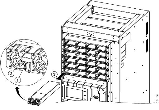
Remove the top and bottom front grilles by unsnapping them from the snap joiners on the LCC.
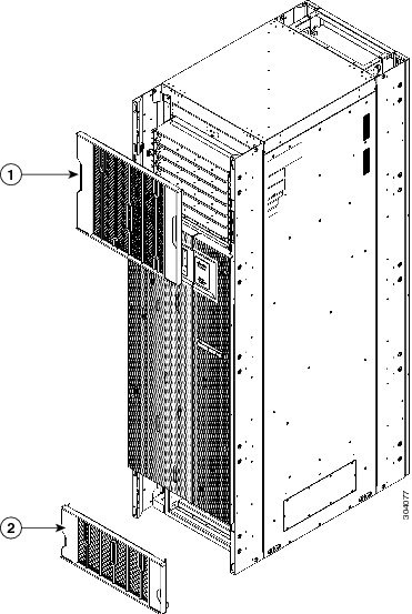
Figure 1. Removing the Front Grilles

1

Front top grille

2

Front bottom grille

Step 2

Remove the front doors.
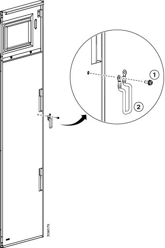
  1. Open the doors and remove the grounding cables by loosening and removing the pan-head screws (See below figure).

  2. Lift the doors up and off the hinge attachment pins and pull away from the LCC.

    Figure 2. Grounding Cables

    1

    Pan-head screw

    2

    Grounding cable

Step 3

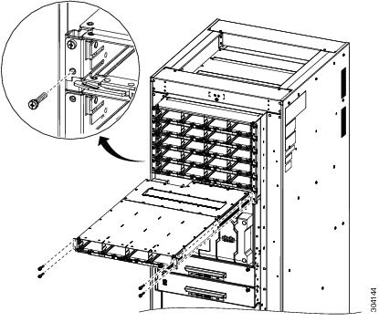
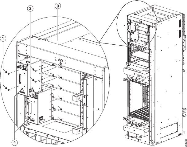
Remove the door hinge attachments, three left and three right, by removing two pan-head screws each (See below figure).
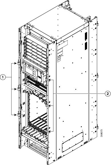
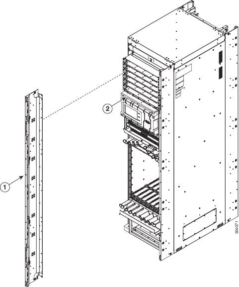
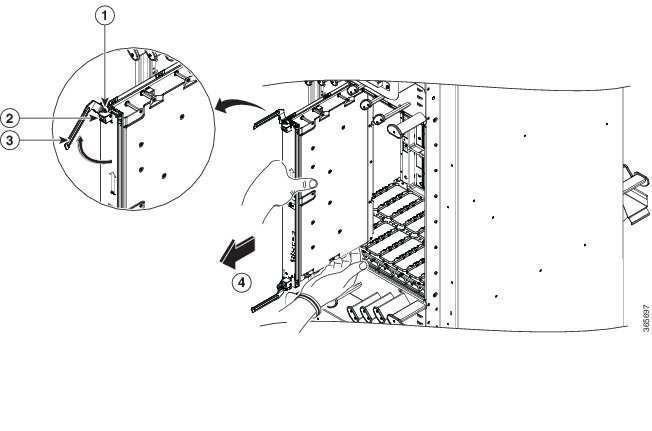
Figure 3. Removing the Door Hinge Attachments—Front of the LCC

1

Left door hinge attachments

2

Right door hinge attachments

Step 4

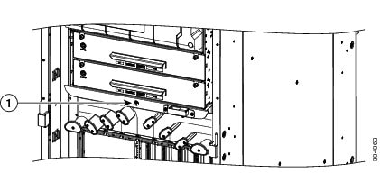
Remove the left and right vertical cable troughs from the front of the LCC (See figure below)) by using the screwdriver to loosen the pan-head screws counterclockwise and remove them from the cable troughs.

Note 
We recommend that you use two people to remove the vertical cable troughs, one person to hold the vertical cable troughs while the other person removes the pan-head screws.
Figure 4. Exterior Cosmetics for the Front of the LCC

1

Vertical cable troughs (one per side), each attached to the LCC with eight pan-head screws

2

Craft panel display cover

Step 5

If necessary, remove the craft panel located on the front of the LCC (see above figure). Usually it is not necessary to remove this panel. The craft panel (Cisco PID NCS-CRFT=) is a field replaceable unit.

  1. Loosen the four captive screws on the craft display panel.

  2. Pull the craft display panel away from the LCC to remove.

  3. Loosen the four captive screws on the sheet metal craft panel.

  4. Pull the craft panel away from the LCC to remove.


Removing the Rear Exterior Cosmetics


Note

While it is possible to remove most of the rear cosmetic parts on the fabric chassis separately, some parts (such as a vertical cable trough) require that other parts be removed first.

Steps

To remove the rear cosmetics, perform the following steps:

Procedure

Step 1

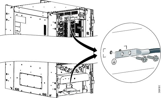
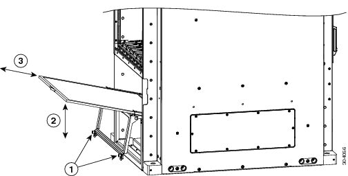
Remove the exhaust air deflector by carefully pulling its mounting tabs away from the brackets on the vertical cable troughs.
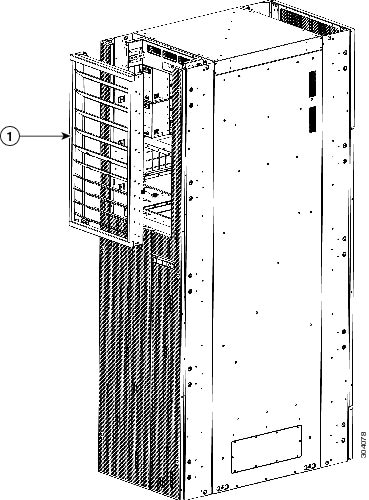
Figure 5. Exhaust Air Deflector on the Rear of the LCC

1

Exhaust air deflector

Step 2

Remove the Rear Doors

  1. Open the doors and remove the grounding cables by loosening and removing the pan-head screws.

  2. Lift the doors up and off the hinge attachment pins and pull away from the LCC.

    Figure 6. Grounding Cables

    1

    Pan-head screw

    2

    Grounding cable

Step 3

Remove the door hinge attachments, three left and three right, by removing the two pan-head screws each.
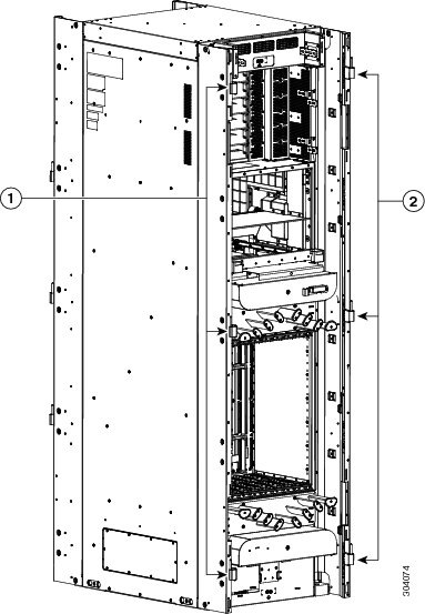
Figure 7. Door Hinge Attachments—Rear of Chassis

1

Left door hinge attachments

2

Right door hinge attachments

Step 4

Remove the exhaust plenum bracket by removing the eight pan-head screws (four on each side).
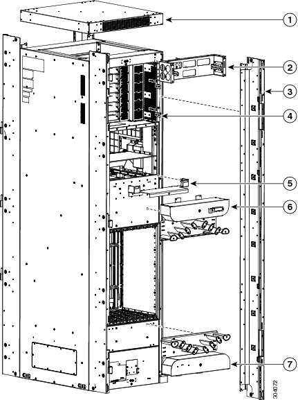
Figure 8. Exterior Cosmetic For the Rear of the LCC

1

Top cap

3

Vertical cable troughs (one per side), each attached to the LCC with eight pan-head screws

2

Exhaust plenum bracket

Step 5

Remove the top cap from the top of the LCC by removing the four screws from the tops of the vertical cable troughs.

Step 6

Remove the left and right vertical cable troughs by using the screwdriver to loosen the 16 pan-head screws counterclockwise and remove them from the cable troughs.

Note 
We recommend that you use two people to remove the vertical cable troughs, one person to hold the vertical cable troughs while the other person removes the pan-head screws.

Removing the Power Components

This section describes how to remove power components from the Cisco NCS 6008 LCC.


Note

Although there are differences between AC and DC power trays and PMs, they are removed using the same procedures.

While it is possible to remove power components from the Cisco NCS 6008 LCC separately, some parts (such as the power tray) require that other parts be removed first.

We recommend that you remove the power components in the order outlined in this section.

Removing AC Input Power Cords

This section describes how to remove AC input power cords from a power tray.

Prerequisites

Remove the exhaust air deflector from the rear of the LCC. Power off the AC PMs in the tray you want to disconnect.


Note

Before removal, make sure that the input power cables are not energized.

Required Tools and Equipment

  • ESD-preventive wrist strap

  • 6-inch, number-1 Phillips screwdriver

Steps

To remove the AC input power cords, go to the rear of the LCC and perform the following steps:

Procedure

Step 1

Attach the ESD-preventive wrist strap to your wrist and connect its leash to one of the two ESD connection sockets on the rear of the LCC. You can also connect the ESD-preventive wrist strap leash to any bare metal surface on the LCC. See Preventing Electrostatic Discharge.

Step 2

Verify that the AC input source breaker is in the OFF position.

Step 3

Use the screwdriver to loosen the screws that clamp the cords in place.

Figure 9. AC Input Power Cords Connected to the Power Tray
Step 4

Remove the cords from the cord clamps.


Removing DC Input Power Cables

This section describes how to remove DC input power cables from a power tray terminal block.

Prerequisites

Remove the exhaust air deflector from the rear of the LCC. Power off the DC PMs in the tray you want to disconnect.


Note

Before removal, make sure that the input power cables are not energized.

You need the following tools to perform this task:

  • ESD-preventive wrist strap

  • 6-inch, number-1 Phillips screwdriver

  • 3/8-inch ratchet wrench with 7/16-pt. socket

  • Voltmeter

Steps

To disconnect DC input power cables, go to the rear of the LCC and perform the following steps:

Procedure

Step 1

Attach the ESD-preventive wrist strap to your wrist and connect its leash to one of the two ESD connection sockets on the rear of the LCC. You can also connect the ESD-preventive wrist strap leash to any bare metal surface on the LCC. See Preventing Electrostatic Discharge.

Step 2

Using the voltmeter, verify that there is no voltage on the cables that are about to be removed.

Step 3

Use the screwdriver to remove the screw that secures the terminal block cover into the mounting standoff.

Step 4

Slide the terminal block cover downwards.

Step 5

Remove the terminal block cover.

Step 6

Using the ratchet wrench, remove the positive and negative cable pairs from each terminal block.

Note 
When a cable is removed from the rear of the DC power tray, we recommend that it should be wrapped with standard black electrical tape.
Step 7

Replace the terminal block cover.


Removing a Power Module Slot Cover

This section describes how to remove a PM slot cover from a PM slot in an AC or DC power tray.

Steps

To remove a PM slot cover from the front of a power tray, perform the following steps:

Procedure

Step 1

Gently pinch the tabs on the top of the PM slot cover to partially detach the slot cover from the slot.

Step 2

Slide the PM slot cover out by removing the tabs on the bottom of the PM slot cover from the two holes on the bottom of the slot.

Figure 10. PM Slot Cover on the Front of a Power Tray

Removing an AC or DC Power Module

This section describes how to remove a power module from a power tray.

Prerequisites

Before performing this task, you must first remove the top grille on the front side of the LCC, if installed.


Note

It is not necessary to turn off the switch on the power tray to remove individual power modules. Power modules support OIR, so they can be removed and replaced with the power on and the system operating.

Required Tools and Equipment

  • ESD-preventive wrist strap
  • 6-inch, number-1 Phillips screwdriver

Steps

To remove a power module from the front of a power tray, perform the following steps:

Procedure

Step 1

Attach the ESD-preventive wrist strap to your wrist and connect its leash to the ESD connection socket on the front side of the LCC. You can also connect the ESD-preventive wrist strap leash to any bare metal surface on the LCC.

Step 2

Using the screwdriver, unscrew the ejector lever screw.

Figure 11. Removing a PM from a Power Tray

1

Ejector lever screw

3

Power module

2

Ejector lever

Step 3

Rotate the ejector lever down to unseat the PM.

Step 4

Slide the PM out of its bay in the power tray while supporting it with your other hand.


Removing an AC or DC Power Tray

This section describes how to remove a power tray from the Cisco NCS 6008 LCC.


Note

As a requirement to receive Cisco support, all six power trays must be installed in the LCC.

Prerequisites

  • Power off the power shelf that houses the power tray you are about to install by using the 1/0 power switch on the respective PCM.

  • Completely power off the entire system at the supply circuit breakers before installing a power tray.

  • Remove the top grilles from both the front and rear sides of the LCC, if installed.

  • Ensure the power tray you are about to install is empty. It is not necessary to turn off the switch on the power tray to remove individual power modules. Power modules support OIR, so they can be removed and replaced with the power on and the system operating.


Caution

The I/O switch on each power shelf only disables the output of the PMs in that shelf. The inputs to the PMs remain hot, as well as the system’s internal busbar (due to the other power shelf).

Required Tools and Equipment

  • 6-inch, number-2 Phillips screwdriver

Steps

To remove an AC or DC power tray, perform the following steps:

Procedure

Step 1

Use the screwdriver to loosen the four M4 x 10 mm screws that attach the power tray to the LCC.

Figure 12. Removing a Power Tray from the LCC
Step 2

Pull both the left and right ejector handles out at the same time to eject the power tray from the LCC. Slide the power tray all the way out of the LCC.

Caution 
Because of the weight of the power tray, 20 lb (9 kg), and the height at which the power tray is installed in the LCC, you should be especially careful while removing and carrying the power tray. To prevent injury, avoid sudden twists or lateral moves.
Caution 
Do not use the ejector handles for lifting or supporting the power tray, because this could severely damage the handles.

Removing the Chassis Ground Cable

This section describes how to remove the chassis ground cable on the Cisco NCS 6008 LCC.

Prerequisites

Before performing this task, completely power off the entire system. Remove all AC or DC input power connections.


Caution

Do not remove the ground cable unless the LCC is powered off and to be replaced.


Required Tools and Equipment

  • 3/8-inch drive socket wrench

  • 10-mm 6-pt. socket

Steps

To remove the ground cable from the LCC, remove the two M6 bolts that attach the ground cable to the NEBS grounding point.

Figure 13. NEBS Bonding and Grounding Point

Removing a Power Control Module

This section describes how to remove a power control module (PCM) from the Cisco NCS 6008 LCC.

The LCC is shipped with two power control modules (PCMs) preinstalled. The PCM is not a field-replaceable unit, however you can order one from Cisco at the following URL (Cisco login required): https://cisco-apps.cisco.com/cisco/psn/commerce.

The PCMs are located behind the two power shelves (PS0 and PS1) on the back of the LCC. Each power shelf has a set of three power trays and a PCM with its own I/O power switch.

Required Tools and Equipment

  • ESD-preventive wrist strap

  • Number 1 Phillips-head screwdriver

  • 8 to 10-inch Number 2 magnetic screwdriver

  • Replacement PCM (NC6-PCM=)

Steps

Procedure

Step 1

Attach the ESD-preventive wrist strap to your wrist and connect its leash to the ESD connection socket on the front side of the LCC (as shown in the following figure). You can also connect the wrist strap to any bare metal surface on the LCC.

Figure 14. ESD Jack—Front Side of the LCC.

1

ESD jack (two on each side of the LCC)

Step 2

Power off each power shelf by using turning the I/O power switch to OFF on the respective PCM.

Step 3

Completely power off the entire system at the supply circuit breakers.

Step 4

Remove the four M4 Phillips pan-head screws from each power tray. Using the ejector handles, slide the three power trays forward just enough to disengage the connector to the PCM without removing the power cables (approximately 1-inch).

Note 
The power trays must be pushed out so that the PCM freely disengages from the connector.
Step 5

Using the magnetic screwdriver, remove the screws from the PCM.

  1. Loosen and remove the two 6-32 pan-head screws on the left front face of the PCM.

  2. Loosen and remove the three 6-32 flat-head screws on the right side flanges of the PCM.

Figure 15. Removing a PCM

1

Two 6-32 pan-head screws

3

Power trays (three trays for each PCM)

2

Three 6-32 flat-head screws

4

Two PCMs

Step 6

Using the magnetic screwdriver, attach the replacement PCM.

  1. Re-insert and tighten the two 6-32 pan-head screws on the left front face of the PCM.

  2. Re-insert and tighten the three 6-32 flat-head screws on the right side flanges of the PCM.

Step 7

Push each power tray in until it engages with the power shelf connectors.

Step 8

Re-insert and tighten the four pan-head screws for each power tray.


Replacing the Fan Trays and Air Filter


Note

The LCC is shipped with the two fan trays and an air filter preinstalled.

Information About the Air Circulation Components

About the Fan Trays

The NCS 6008 LCC is equipped with two fan trays to provide the cooling required to protect critical components throughout the system from overheating. This arrangement is designed to ensure high availability in the cooling system. Typically, the fan trays share the cooling load, but each is capable of cooling chassis in normal operating conditions (up to 40°C [104°F] ambient room temperature) if the other is down. This is a diagram of the air circulation in the NCS 6008 LCC.

Figure 16. Airflow Through the Cisco NCS 6008 LCC

1

Front side of LCC

6

Air flow through PMs

2

Air inlet plenum

7

Exhaust air from PMs

3

Air filter

8

Air exhaust plenum

4

Front cage for LCs

9

Rear cage for FCs and RP cards

5

Fan trays

10

Rear side of LCC

Temperature sensors mounted on the critical components throughout the system are monitored by the system software. Whenever a component breeches the preliminary threshold set for that component, a message is sent to the fan tray to increase fan speed until the temperature returns to normal. If the critical threshold is breeched, the card is shut down to avoid permanent damage.

Normally, all fans operate in unison to provide the appropriate air circulation in the chassis. When an adjustment needs to be made in the air flow, messages are sent to both fan trays to increase or decrease fan speed. If one fan tray fails or is removed, a message is sent to other fan tray to increase fan speed to the maximum. Should both fan trays be down at the same time on a running system, a general alarm is issued and a CLI warning message sent stating that the system will shut down in 45 seconds to avoid component damage in the system. Any fan tray that is down or removed should be replaced as soon as possible to ensure adequate redundant protection in the chassis.


Note

The upper and lower fan trays are interchangeable and installed in the same manner.

There are two fan tray models: NC6-FANTRAY and NC6-FANTRAY-2.

  • NC6-FANTRAY is supported in Cisco IOS XR release 5.0.0 and later. However, it does not support the enhanced air flow and monitoring capabilities introduced in Cisco IOS XR release 6.1.2.

    Figure 17. Fan Tray
  • The NC6-FANTRAY-2 is supported in Cisco IOS XR release XR 6.1.2 and later. Cisco IOS XR release 6.1.2 introduces enhanced air flow and monitoring capabilities.

    Figure 18. Fan Tray 2

Caution

Both fan trays installed in a chassis must be the same type. Do not install NC6-FANTRAY and NC6-FANTRAY-2 fan trays in the chassis.

Caution

If you install two NC6-FANTRAY-2 in a system that is running software earlier than Cisco IOS XR 6.1.2, the software does not recognize the fan tray and the system will shut down within 45 seconds.

A bicolor status LED is located on the front panel of the fan tray. The LED signals the operational status of the fan tray. This table describes how the LED colors are used.

Table 1. Fan Tray LED

State

Description

Green

The fan tray is operating normally.

Yellow

The fan tray has one or more errors detected.

Off

No power is applied to the fan tray.

About the Air Filter

The Cisco NCS 6008 LCC has a serviceable air filter mounted in a slide-out tray accessible from the front of the LCC just below the card cage (Figure 1). The air filter removes dust from the room air drawn into the LCC by the two fan trays. Once a month (or more often in dusty environments), you should examine the air filter. Replace it if it appears excessively dirty or damaged.

Failure to replace a compromised air filter can result in insufficient air circulation through the LCC and temperature-related environmental alarms. For information about replacing the air filter, see the Replacing the Air Filter.


Note

To comply with Telecordia GR-63-Core standard air filter requirements for NEBS deployments, the air filter must be replaced, not cleaned.

Replacing Air Circulation Components

Replacing the Fan Tray

Prerequisites

Before performing this task, open the cosmetic doors, if installed.

If you are installing Fan Tray 2 (NC6-FANTRAY-2), make sure the system is running Cisco IOS XR 6.1.2 or later.


Caution

Both fan trays installed in a chassis must be the same type. Do not install NC6-FANTRAY and NC6-FANTRAY-2 fan trays in the chassis.

Caution

If you install two NC6-FANTRAY-2 in a system that is running software earlier than Cisco IOS XR 6.1.2, the software will not recognize the fan tray and the system will shut down within 45 seconds.
Required Tools and Equipment
  • ESD-preventive wrist strap

  • 6-inch, number-1 Phillips screwdriver

  • Fan tray (NC6-FANTRAY-2 or NC6-FANTRAY)

Steps

To replace a fan tray, perform the following steps:

Procedure

Step 1

Attach the ESD-preventive wrist strap to your wrist and connect its leash to the ESD connection socket on the front side of the LCC Figure 1. You can also connect the ESD-preventive wrist strap leash to any bare metal surface on the LCC.

Step 2

Using the screwdriver, loosen the two captive screws on the fan tray faceplate. If necessary, use a step platform to reach the upper fan tray comfortably.

Step 3

Pull firmly on the fan tray handle to pull it free; two people are required to remove the fan tray.

Caution 
Because of the weight of the fan tray, approximately 30 lb (14 kg), two people are required to remove the fan tray. You should be especially careful while removing the fan tray from the LCC. To prevent injury, keep your back straight and lift with your legs, not your back. Avoid sudden twists or lateral moves. It is safer to use two people to remove the fan tray rather than a single person.
Step 4

Grasp the fan tray handle and pull it straight out to disconnect the fan tray from the connector mounted on the front of the fan tray bay on the rear side of the LCC. Slide the fan tray halfway from the fan tray bay.

Step 5

Use your free hands to support the fan tray, and then slide the fan tray completely from the fan tray bay.

Step 6

To install the replacement fan tray, use both hands to support and position the fan tray in front of the fan tray bay (label is on top).

Step 7

Slide the fan tray into the fan tray bay. Stop when the fan tray makes contact with the LCC connector in the back of the fan tray bay.

Caution 
To prevent damage to the LCC connector, do not use excessive force when inserting a fan tray into its bay.
Step 8

Firmly push on the fan tray handle to seat the fan tray connector in the LCC connector. When completely seated, the fan tray faceplate flanges meet the rear side of the LCC.

Note 
All electrical and control line connections are made automatically when the connectors mate. The LED will light when the fan tray is inserted. The LED is yellow initially, until the system has confirmed it is functioning correctly.
Step 9

Tighten the two captive screws on the fan tray faceplate.


Replacing the Air Filter


Note

We recommend that you change the air filter every three months. The filter is sold in packs of 5 (Cisco PID NC6-5XFILTER=).

Note

A lattice of wire exists on both sides of the filter material with an arrow denoting airflow direction and a pair of sheet metal straps on the downstream side of the filter assembly.

Caution

Never operate the Cisco NCS 6008 LCC without an air filter. Operating the LCC without a filter for an extended time can result in damage to the chassis hardware.


Steps

To replace the air filter, follow these steps:

Procedure

Step 1

Remove the lower grille, if installed.

Step 2

Loosen the two captive screws on the filter cover. The filter will automatically drop down.

Figure 19. Replacing the Air Filter—Front Side of LCC

1

Two captive screws

3

Slide old air filter out, slide new air filter in.

2

Pull outward and swing down to access filter, swing up and push in after replacement.

Step 3

Pull outward on the center of the filter door to pull it free.

Step 4

Grasp the pull tab in the center of the air filter, and slide it out from the slot.

Step 5

Install the replacement air filter.

Note 
Verify air flow direction when installing the new air filter. An air flow direction arrow is stamped on the air filter frame and should be installed pointing up.
  1. Slide the new air filter into the slot.

  2. Swing up and push in the filter cover.

  3. Tighten the two captive screws on the front of the filter cover.


Removing the Route Processor Cards and Fabric Cards

This section describes how to remove the route processor (RP) cards and fabric cards (FCs) from the LCC.

Guidelines for Removing a Card

  • Online (in-service) insertion and removal (OIR) is supported, enabling you to remove the cards while the LCC is operating. OIR is seamless to users on the network, maintains all routing information, and ensures session preservation. It is not necessary to notify the software or reset the power. OIR removes power to a specific slot before the card is replaced. The power remains on for all other card slots.


Note

We recommend that you perform a graceful shutdown to shut down a card prior to removing it from the LCC. See the Steps for OIR Card Removal.
  • The different cards in the LCC are attached to the LCC itself using a pair of ejector levers and captive screws. The two ejector levers release the card from its backplane connector. The exact locations of the ejector levers and captive screws can vary slightly from card to card, but are generally in the same locations: on the upper and bottom ends of the faceplate.

  • When you remove an FC, you must press the OIR button before using the ejector levers to ensure that the connector pins disconnect from the backplane in the sequence expected by the LCC.

  • Any unused card slots that are uncovered allows air used for LCC cooling to escape. To ensure proper air flow and maintain system EMC and safety compliance, any unused FC slots must contain impedance carriers (see the Installing and Removing an Impedance Carrier and the Slot Numbers–Front and Rear Side).

Removing an RP Card

Prerequisites

Before performing this task, open the cosmetic doors, if installed. The RP cards are hot-swappable.

Perform these tasks when you are certain that the other RP card in the chassis is operational and, if not already the Active RP, is ready to assume control (this happens automatically). Failure to follow these guidelines can result in interruptions in data communications and network connectivity.


Warning

Class 1 Laser Product. Statement 113


Warning

Because invisible radiation may be emitted from the aperture of the port when no fiber cable is connected, avoid exposure to radiation and do not stare into open apertures. Statement 125


Required Tools and Equipment

  • ESD-preventive wrist strap
  • Number-2 Phillips screwdriver or number-2 common (flat-head) screwdriver

Steps

To remove an RP card, perform the following steps:

Procedure

Step 1

Attach the ESD-preventive wrist strap to your wrist and connect its leash to one of the two ESD connection sockets on the rear side of the chassis (Figure 1). You can also connect the ESD-preventive wrist strap leash to any bare metal surface on the chassis.

Step 2

Identify the card to be removed from the card cage. Remove any cables connected to the front panel of the card.

Step 3

Use the number-2 Phillips screwdriver or number-2 common (flat-head) screwdriver to turn the two captive screws on the front panel of the card counterclockwise to loosen the card from the slot.

Caution 
To prevent ESD damage, handle an RP card by its ejector levers or the LC carrier edges only. Do not touch any of the electrical components, pins, or circuitry.
Figure 20. Removing an RP Card

1

Captive screw

3

Direction of removal

2

Ejector lever

Step 4

Simultaneously pivot the ejector levers away from the faceplate to release the RP card from the midplane connectors.

Step 5

Grasp the two card ejector levers and simultaneously pivot both ejector levers 90 degrees away from the front edge of the card carrier to unseat the card from the backplane connector.

Step 6

Grasp the ejector levers with both hands and gently pull the RP card halfway from the slot. Do not use the bracket to pull the RP card from the slot.

Step 7

Move one hand under the RP card to guide it. Avoid touching the RP card printed circuit board, components, or any connector pins.Touching only the metal card carrier, slide the card from the slot and place it directly into an antistatic sack or other ESD-preventive container. If you plan to return a defective card to the factory, repackage it in the shipping container that you received with the replacement card.


Removing a Fabric Card

Guidelines for Handling CXP2 Optical Modules


Warning

Hot surface. Statement 1079

The metal surfaces on the CXP2 can run hot. Use caution when removing CXP2 optical modules from the Universal Fabric Card (UFC).

1

Metal surfaces

A thermoplastic sleeve is provided for each CXP2 port.

You can install the thermoplastic sleeve around the base of the CXP2 before you install the CXP2, as shown in the following figure.


Note

You can leave the sleeve on the CXP2 optical module while it is installed in the fabric card.

If a CXP2 is already installed, you can install the thermoplastic sleeve around the base of the CXP2 before you remove it from a transceiver socket, as shown in the following figure.

Alternatively, you can remove a CXP2 optical module (with or without the thermoplastic sleeve) and hold it in the provided silicon foam pad, as shown in the following figures.

Prerequisites

Before performing this task, open the cosmetic doors, if installed.

Required Tools and Equipment

  • ESD-preventive wrist strap

  • Number-2 Phillips screwdriver or number-2 common (flat-head) screwdriver

Steps

To remove a fabric card, perform the following steps:

Procedure

Step 1

Attach the ESD-preventive wrist strap to your wrist and connect its leash to one of the two ESD jacks on the rear side of the chassis (Figure 1). You can also connect the ESD-preventive wrist strap leash to any bare-metal surface on the chassis.

Step 2

Identify the FC to be removed from the card cage. Use the number-2 Phillips screwdriver or number-2 common (flat-head) screwdriver to turn the two captive screws, on the front panel of the card counterclockwise to loosen it from the slot.

Figure 21. Removing a Fabric Card

1

OIR button

3

Ejector lever

2

Captive screw

4

Direction of removal

Step 3

Press the OIR buttons on the top and bottom of the card faceplate to release the ejectors ( Figure 6-18 ).

Note 
Wait for the STATUS LED to turn to yellow. This indicates that the card is ready for removal.
Step 4

Grasp the two card ejector levers and simultaneously pivot both ejector levers 70 degrees away from the front edge of the card carrier to unseat the card from the midplane connector.

Step 5

Touching only the metal card carrier, slide the card from the slot and place it directly into an antistatic bag or other ESD-preventive container. If you plan to return the defective card to the factory, repackage it in its original shipping container.