Installing RP Cards, Line Cards, and Fabric Cards

This chapter provides instructions on how to install cards and their associated components in the Cisco NCS 6000 Line Card Chassis (LCC).

About Installing Cards and Associated Components

Preventing Electrostatic Discharge

Electrostatic discharge (ESD) damage, which can occur when electronic cards or components are improperly handled, results in complete or intermittent failures. We recommend use of an ESD-preventive wrist strap whenever you handle network equipment or one of its components.

  • Always use an ESD-preventive wrist or ankle strap, and ensure that it makes good skin contact. Connect the equipment end of the connection cord to an ESD jack ( Figure 2-4 ) or a bare metal surface on the chassis (ensure that the chassis is grounded).

  • Handle a card by its ejector levers, when applicable, or its metal carrier only; avoid touching the board or connector pins (see the Guidelines for Installing and Removing a Card section).

  • Place a removed card board-side-up on an antistatic surface or in a static-shielding bag. If you plan to return the component to the factory, immediately place it in a static-shielding bag.

  • Avoid contact between a card and clothing. The wrist strap protects the board from only ESD voltage on the body; ESD voltage on clothing can still cause damage.

  • Be careful not to lay any tools on the aluminum honeycomb panel, or insert your fingers into the panel.

Guidelines for Installing and Removing a Card

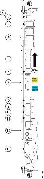
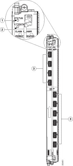
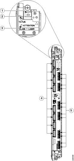
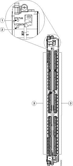
  • Every card has a label with an arrow on its faceplate showing which side is up for installation.

  • The card connector of every FC, LC, and RP card is keyed to ensure that the card is installed correctly in the slot.


    Note

    RP card faceplates and the RP card slots on the LCC are labeled with the square symbol. FC faceplates and the FC slots on the LCC are labeled with the circle symbol.
  • Online insertion and removal (OIR) is supported enabling you to install a card while the LCC is operating. OIR removes power to a specific slot before the card is replaced. The power remains on for all other card slots.

    OIR is seamless to users on the network, maintains all routing information, and ensures session preservation. We recommend that you perform a graceful shutdown to shut down an FC, LC, or RP card prior to removing it from the LCC. See the Steps for OIR Card Removal section.


    Note

    Graceful shutdown is critical to prevent file system corruption on the SSD in the RP or LC.
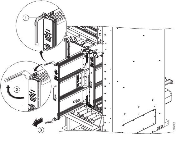
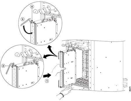
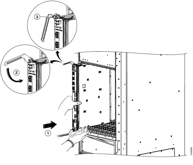
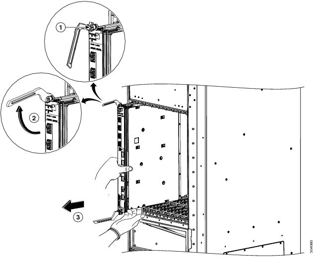
  • Prior to installing a fabric card, you must push the OIR button on both the upper and lower ejectors to release the mechanical latches.

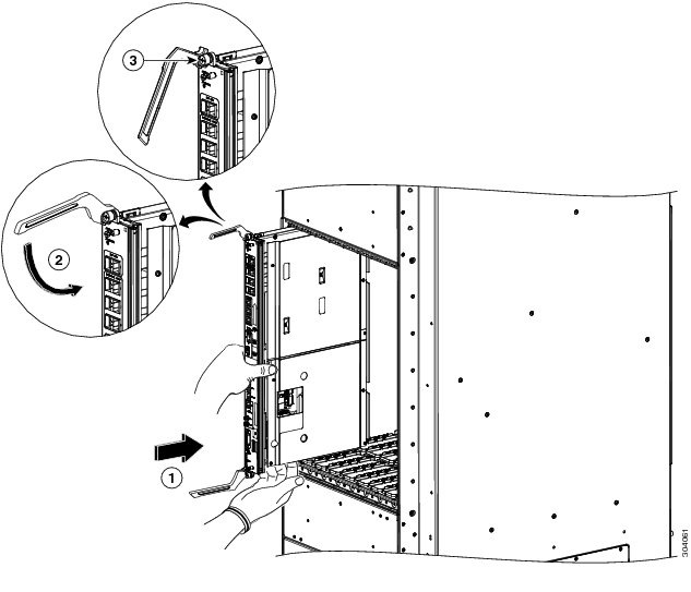
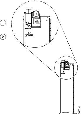
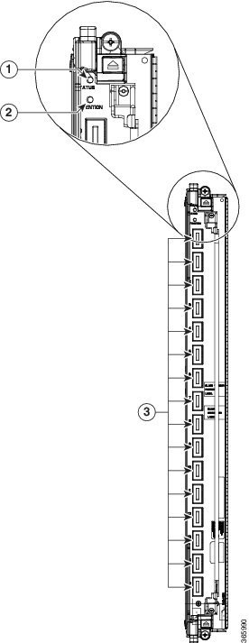
  • The ejector levers and captive screws on the cards secure the cards to the LCC and ensure proper electrical connection. The ejector levers and captive screws are located at the upper and bottom ends of the faceplate.

  • The chassis is shipped with all card slots containing either impedance carriers or a plastic cover to help maintain chassis stiffness and prevent any damage to the chassis during shipment.


Note

The NC6-LC-BLANK impedance carrier is no longer supported. Replace the NC6-LC-BLANK with the NC6-LC-BLANK2 impedance carrier (front of the LCC) when installing new FCs or performing OIR on existing FCs (rear of the LCC).
  • All unused card slots must be covered to ensure proper air circulation and cooling within the chassis. Install NC6-LC-BLANK2 impedance carriers in all slots that are not being used. This ensures proper air flow and maintains system EMC and safety compliance. See the Installing an Impedance Carrier section.

  • Install LCs and NC6-LC-BLANK2 impedance carriers (front of the LCC) before installing the FCs and RP cards (rear of the LCC).

  • Fully insert all FCs and RP cards into the chassis before tightening their captive screws.

  • For information about the slot numbers, see the section.


Caution

The chassis may indicate a hardware failure if you do not follow proper procedures. Remove or install only one card at a time. Allow at least 15 seconds for the chassis to complete its tasks before removing or installing another card.

Steps for OIR Card Removal

Follow these steps to perform a graceful OIR on the FC, LC, or RP card.

Procedure

Step 1

If you are removing an FC, shut down the fabric plane X (where X is in the range of 0 to 5). If you are removing an LC or RP, go to Step 2.

Example:

sysadmin-vm:0_RP0# config
sysadmin-vm:0_RP0(config)# controller fabric plane 0 shutdown
sysadmin-vm:0_RP0(config)# commit
sysadmin-vm:0_RP0(config)# end

Step 2

Shut down the FC, LC, or RP card location rack /slot (where rack is the rack number in the range of 0 to 15 and F0 to F3, and slot is the slot in the range of 0 to 7 for an LC, FC0 to FC5 for an FC, and RP0 to RP1 for an RP). Confirm the shutdown.

Example:

sysadmin-vm:0_RP0# hw-module location 0/FC0 shutdown
Wed Aug  10 23:52:35.610 UTC
Shut down hardware module ? [no,yes] y
0/RP0/ADMIN0:Aug 10 23:52:47.042 : shelf_mgr[2897]: %INFRA-SHELF_MGR-4-CARD_SHUTDOWN :
Shutting down card 0/FC0
result Card graceful shutdown request on 0/FC0 succeeded.

Step 3

Before you remove the card, use the show platform command to verify that it is powered off. Do not remove the card until the output of the show platform command indicates that the card has been powered off.

Example:

sysadmin-vm:0_RP0# # show platform location 0/FC0
Wed Aug  10 23:54:02.366 UTC
Location  Card Type               HW State      SW State      Config State
----------------------------------------------------------------------------
0/FC0     NC6-FC                  POWERED_OFF   N/A           NSHUT

Step 4

Remove the card using the appropriate procedure:

Step 5

Reinstall the card using the appropriate procedure:

Step 6

Use the show platform command to verify that the card is operational .

Example:

sysadmin-vm:0_RP0# # show platform location 0/FC0
Wed Aug  10 23:54:02.366 UTC
Location  Card Type               HW State      SW State      Config State
----------------------------------------------------------------------------
0/FC0     NC6-FC                  OPERATIONAL   OPERATIONAL   NSHUT

Step 7

If you are installing a fabric card, unshut the fabric plane X .

Example:

sysadmin-vm:0_RP0# config
sysadmin-vm:0_RP0(config)# no controller fabric plane 0 shutdown
sysadmin-vm:0_RP0(config)# commit
sysadmin-vm:0_RP0(config)# end


About Cable Management Brackets

The Cisco NCS 6008 LCC has cable management features for both the front and rear sides of the chassis. These features organize the interface cables entering and exiting the different cards, keeping them out of the way and free of sharp bends that may damage the cables.

  • The front and rear sides have horizontal cable management brackets above and below the card cages (see Front View of the Cisco NCS 6008 LCC and Rear View of the Cisco NCS 6008 LCC).

  • The front and rear sides have vertical cable troughs on the left and right of the chassis.

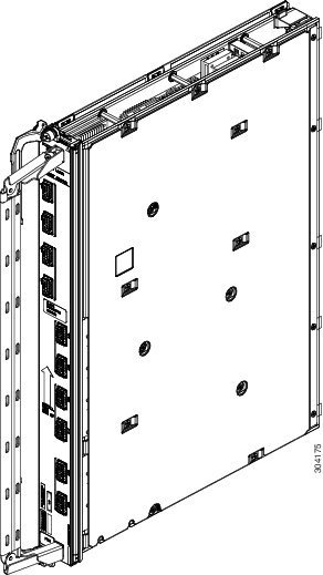
  • A vertical cable management bracket is preattached to the faceplate of a LC, FC, and RP card (see figure below).

Figure 1. LC Vertical Cable Management Bracket

Installing and Removing an Impedance Carrier

The chassis ships with impedance carriers installed in the LC slots.


Note

The NC6-LC-BLANK impedance carrier is no longer supported. Use PID NC6-LC-BLANK2= to order a spare impedance carrier.

Note

The NC6-LC-BLANK2 uses captive screws and ejector levers to secure the impedance carrier to the LCC.
Figure 2. NC6-LC-BLANK2

Installing an Impedance Carrier

This section describes how to install an impedance carrier in the Cisco NCS 6008 LCC.

Prerequisites

Before performing this task, open the cosmetic doors, if installed, and ensure that the slot in which you are about to install the impedance carrier is empty.

Required Tools and Equipment

  • Number-2 Phillips screwdriver or number-2 common (flat-head) screwdriver

  • LC impedance carrier (NC6-LC-BLANK2)

Steps

To install the NC6-LC-BLANK2 impedance carrier, perform the following steps:

Procedure

Step 1

Orient the impedance carrier according to the up arrow on the faceplate.

Step 2

Use both hands while inserting an impedance carrier. Use one hand on the faceplate and the other hand along the base of the impedance carrier to guide it into the slot.

Step 3

Carefully slide the impedance carrier into the slot until the ejector levers engage the catches, and then stop.

Step 4

Simultaneously pivot the ejector levers toward the faceplate of the impedance carrier. Do not force the impedance carrier; the ejector levers properly seat the impedance carrier against the midplane.

Figure 3. Installing NC6-LC-BLANK2 Impedance Carrier

1

Direction of insertion

3

Captive screw

2

Ejector lever

Step 5

Use the number-2 Phillips screwdriver or number-2 common (flat-head) screwdriver to fully tighten the captive screws to seat the impedance carrier firmly in the slot.


Removing an Impedance Carrier

This section describes how to remove an impedance carrier from the Cisco NCS 6008 LCC.

Prerequisites

Before performing this task, open the cosmetic doors, if installed.

Required Tools and Equipment

  • Number-2 Phillips screwdriver or number-2 common (flat-head) screwdriver

Steps

To remove an impedance carrier, perform the following steps:

Procedure

Step 1

Identify the impedance carrier to be removed from the card cage. Use the number-2 Phillips screwdriver or number-2 common (flat-head) screwdriver to turn the two captive screws on the front panel of the card counterclockwise to loosen it from the slot.

Step 2

For NC6-LC-BLANK2, grasp the two card ejector levers and simultaneously pivot both ejector levers 70 degrees away from the front edge of the card carrier to unseat the impedance carrier from the midplane connector.

Figure 4. Removing the NC6-LC-BLANK2 Impedance Carrier

1

Captive screw

3

Direction of removal

2

Ejector lever

Step 3

Grasp the impedance carrier handle with one hand and gently pull it halfway from the slot.

Step 4

Place one hand under the impedance carrier to guide it.

Step 5

Holding the impedance carrier underneath and by the handle, pull it from the slot, and set it carefully aside.


Installing a Route Processor Card


Warning

Class 1 Laser Product. Statement 113

Warning

Because invisible radiation may be emitted from the aperture of the port when no fiber cable is connected, avoid exposure to radiation and do not stare into open apertures. Statement 125

Installing an RP Card

Every Cisco NCS 6008 LCC contains two route processor (RP) cards in dedicated slots on the rear side of the chassis. The RP cards are identical. One RP card installs into slot RP0 on the left of the card cage, while the second RP card installs into slot RP1 on the right of the card cage.

Prerequisites


Caution

Install one RP card at a time. Allow at least 15 seconds for the chassis to complete its tasks before installing another RP card. The chassis may indicate a hardware failure if you do not follow proper procedures.

Required Tools and Equipment

  • ESD-preventive wrist strap

  • Number-2 Phillips screwdriver or number-2 common (flat-head) screwdriver

  • RP card (Cisco PID NC6-RP)

Steps

To install an RP card, perform the following steps:

Procedure

Step 1

Attach the ESD-preventive wrist strap to your wrist and connect its leash to one of the two ESD jacks on the rear side of the chassis (see Preventing Electrostatic Discharge). You can also connect the ESD-preventive wrist strap leash to any bare metal surface on the chassis.

Step 2

Remove the card from its antistatic packaging.

Step 3

At the top and bottom of the card faceplate, press the OIR buttons to release the ejector levers.

Step 4

In the rear of the chassis, select the RP slot that you want to install the card in. The two slots at either end of the card cage are for RP cards only. For information about the location of the RP slots, see .

Step 5

Locate the arrow on the faceplate and orient the card so that the arrow points up. The backplate of the card is on your left.

Step 6

For support, place one hand under the card and align the edges formed by the backplate of the card with rail guides in the slot. Avoid touching the card circuitry or any connectors.

Figure 5. Installing an RP Card

1

Direction of insertion

3

Captive screw

2

Ejector lever

Step 7

Gently but firmly slide the card into the slot making sure that the edges stay within the rail guides until the card makes solid contact with the backplane and the ejector levers stiffen.

Note 
If the card does not slide easily into the slot during installation, the edges of the backplate may not be in the rail guides and the card is misaligned or the card is not installed in an RP slot.
Step 8

Gently but firmly close the ejector levers to secure the card in the slot. The card faceplate should be flush with the chassis structure.

Caution 
Do not force the levers to close. If there is undue resistance to closing the ejectors, remove the card completely and reinsert it.
Step 9

Use the number-2 Phillips screwdriver or number-2 common (flat-head) screwdriver to turn the two captive screws on the front panel of the card clockwise to seat the card firmly in the slot.

Step 10

Attach the vertical cable management bracket to the faceplate of the RP card using the two screws that came with it (see About Cable Management Brackets).


Verifying the Installation of an RP Card

This section describes how to verify that the RP card has been properly installed and to troubleshoot the installation in the Cisco NCS 6008 LCC.

This shows the front panel of the RP card.

Figure 6. RP Card Front Panel

1

Status LED—Card status indicator

8

IEEE 1588 Ethernet port

2

Attention LED

9

SYNC0 (BITS/J.211) port

3

Expansion Ethernet ports

10

SYNC1 (BITS/J.211) port

4

Interface Shelf Ethernet ports

11

Time/Frequency Expansion port

5

Three console ports

12

GPS ToD interface (with 1-PPS and 10-MHz coax connectors)

6

External USB port

13

Alarm port

7

Two management LAN Ethernet ports

Troubleshooting the RP Card

Use the Status LED, located on the faceplate of the RP card, to verify the correct installation of the card:

  • When the card is properly installed and no faults are detected, the card status LED turns green.

  • When the card status LED is solid yellow, either software initialization is in progress during bootup or a fault exists on the board.

  • When the card status LED is blinking yellow, the card is not fully seated.

  • When the card status LED is off, verify that the card is installed correctly. There could be no power applied to the card, a power fault, or a hardware fault.

  • Verify that there is power to the card by looking at the indicators on the power tray.


Note

To confirm the location of the card that needs attention, use the hw-module attention-led location node-id command in System Admin Config mode to enable the Attention LED.


If the installed or replaced card fails to operate or to power on after installation:

  • Ensure that the card is seated firmly in the Cisco NCS 6008 chassis slot. One easy way to verify physical installation is to see whether the front faceplate of the card is even with the fronts of the other cards installed in the card cage.

  • Ensure that the ejector levers are latched and that the captive screws are fastened properly. If you are uncertain, unlatch the levers, loosen the screws, and attempt to reseat the card.

  • Examine the power system to see whether the chassis is receiving power.

Inserting a Previously Configured Card

On systems running IOS XR earlier than version 5.2.5: If you insert an RP card that was originally installed in another NCS 6000 system, the saved configuration from that RP card may overwrite the system admin configuration on the current system. To ensure that the system admin configuration is preserved on the current system, perform these steps on the previously configured card:

Procedure


Step 1

Insert the previously configured card into a running NCS 6000 system. Inserting the card into a system that is shut down is not supported.

Note 
Do not connect anything to the management Ethernet interface on the previously configured card until the synchronization and internal PXE boot is complete.
Step 2

Verify that the automatic synchronization of SMUs and internal PXE boot is complete using the show install active command. Compare the output from the previously configured card to that of the existing RP cards.

Step 3

Erase old configurations on the card from the System Administration mode.


attach location <card>
rm -rf /misc/config/confd/
exit

Step 4

Reload the card using hw-module location card reload command.

Step 5

Confirm that the card has come up fully using the show platform command.

Step 6

Commit a configuration change in the System Administration mode.

For example,


config
confdConfig cli timestamp disabled
commit
To change the configuration to its original value, run the command:

config
confdConfig cli timestamp enabled 
commit


About Fabric Cards

The Cisco NCS 6000 switch fabric is a 3-stage cell based architecture with six fabric planes. The fabric cards (FCs) provide the switch fabric for the routing system and perform the cross-connect function of the routing system, connecting every line card (LC) to each other. The switch fabric receives ingress user data from one LC slot and performs the switching necessary to route the data to the appropriate egress LC slot.


Caution

Do not install fabric cards of different types in the same LCC.

S123 Fabric Card (NC6-FC)

The NCS 6000 S123 Fabric Card (FC) implements all three stages of the switch fabric. It is designed to support standalone LCCs only. It has all of the fabric functionality embedded in the card and does not require support of an FCC. The S123 FC does not have optical components to connect to fabric cards in an FCC.

Figure 7. S123 Fabric Card Front Panel

1

Status LED

2

Attention LED

The following table describes the LED indicators for the S123 Fabric Card.

Table 1. S123 Fabric Card LED Indicators

LED

LED Color

Description

STATUS

Green

The card is properly installed and no faults are detected.

Yellow

The software initialization is in progress during bootup or a fault exists on the board.

Flashing yellow (slow)

The card is not fully seated or the slot has detected a parity error.

Off

No power is applied to the card.

ATTENTION

Blue

On: The card needs attention.

Off: The card does not require attention.

Note 

Use the [no] hw-module attention-led location node-id command in System Admin Config mode to enable or disable the Attention LED. The Attention LED is useful for identifying and verifying which card needs attention.

Universal Fabric Card (NC6-FC2-U)

The Universal Farbic Card (UFC) implements all three stages of the switch fabric. It supports the following configurations:

  • Standalone chassis (SC), acting as S123 fabric card

  • Multi-chassis (MC) configuration, acting as S13 fabric card; requires Fabric Card Chassis (FCC) with S2 fabric card (1T mode using CXP transceiver modules) or second-generation S2 fabric card (2T mode using CXP2 transceiver modules)

  • Back-to-back (B2B) configuration, in 1T mode using CXP transceiver modules or 2T mode using CXP2 transceiver modules—provides the same capacity and functionality as a 2+1 multi-chassis configuration

In a back-to-back configuration, the connections between the FCs in the LCCs are implemented through a number of bi-directional optical links using pluggable CXP optical modules. The CXP module uses a 24-fiber MPO connector that supports 12 bi-directional optical links up to 100 meters of OM-4 multi-mode fiber.


Note

Install a CXP transceiver module or an EMI/dust plug (supplied) in all CXP ports. Do not operate the FC with an open port.

For information on cabling a back-to-back system, refer to the Cisco Network Convergence System 6000 Series Routers Migration Guide.

Figure 8. Universal Fabric Card Front Panel

1

Status LED

3

16 CXP ports and LEDs

2

Attention LED

The following table describes the LED indicators for the Universal Fabric Card.

Table 2. Universal Fabric Card LED Indicators

LED

LED Color

Description

STATUS

Green

The card is properly installed and no faults are detected.

Yellow

The software initialization is in progress during bootup or a fault exists on the board.

Flashing yellow (slow)

The card is not fully seated or the slot has detected a parity error.

Off

No power is applied to the card.

ATTENTION

Blue

On: The card needs attention.

Off: The card does not require attention.

Note 
Use the [no] hw-module attention-led location node-id command in System Admin Config mode to enable or disable the Attention LED. The Attention LED is useful for identifying and verifying which card needs attention.

CXP (0 to 15)

Green

The port is correctly connected to the UFC on the second LCC.

Red

One or more links are down or the CXP is connected to the wrong CXP port on the UFC in the second LCC. For troubleshooting information, see the System Administration Command Reference for the Cisco NCS 6000 Series Routers.

Off

The CXP module is not present or is not fully inserted in the fabric card.

S13 Fabric Card (NC6-FC-MC)

The S13 Multi-Chassis (MC) FC implements the first and third stages of the switch fabric. The S13 MC FC is designed to be used in multi-chassis systems and includes optical ports to connect with S2 FCs in FCCs.


Note

The S2 Fabric Card implements the second stage of the switch fabric and resides in the Fabric Card Chassis (FCC). See the Cisco Network Convergence System 6000 Fabric Card Chassis Hardware Installation Guide for more information.

The connections between the LCC and the FCC are implemented through a number of bi-directional optical links. CXP optical modules are used on the S2 FC and S13 FC to connect the two cards together. The CXP module uses a 24-fiber MPO connector that supports 12 bi-directional optical links up to 100 meters of OM-4 multi-mode fiber.

Figure 9. S13 MC Fabric Card Front Panel

1

Status LED

3

16 CXP port LEDs (0 through 15, one per port)

2

Attention LED

4

16 CXP ports

The following table describes the LED indicators for the S13 MC Fabric Card.

Table 3. S13 MC Fabric Card LED Indicators

LED

LED Color

Description

STATUS

Green

The card is properly installed and no faults are detected.

Yellow

The software initialization is in progress during bootup or a fault exists on the board.

Flashing yellow (slow)

The card is not fully seated or the slot has detected a parity error.

Off

No power is applied to the card.

ATTENTION

Blue

On: The card needs attention.

Off: The card does not require attention.

Note 

Use the [no] hw-module attention-led location node-id command in System Admin Config mode to enable or disable the Attention LED. The Attention LED is useful for identifying and verifying which card needs attention.

CXP (0 to 15)

Green

The port is correctly connected to the S2 Fabric Card on the FCC.

Red

One or more links are down. For troubleshooting information, see the System Administration Command Reference for the Cisco NCS 6000 Series Routers.

Off

The CXP module is not present or is not fully inserted in the fabric card.

Installing a Fabric Card

This section describes how to install a fabric card in the Cisco NCS 6000 LCC.

Prerequisites


Caution

Install one fabric card at a time. Allow at least 15 seconds for the chassis to complete its tasks before installing another fabric card. The chassis may indicate a hardware failure if you do not follow proper procedures.


Required Tools and Equipment

  • ESD-preventive wrist strap

  • Number-2 Phillips screwdriver or number-2 flat-head screwdriver

  • Fabric card (NC6-FC, NC6-FC2-U, or NC6-FC-MC)

Steps

To install a fabric card in the NCS 6008 LCC, follow these steps:

Procedure


Step 1

Attach the ESD-preventive wrist strap to your wrist and connect its leash to one of the two ESD jacks on the rear side of the chassis (see Preventing Electrostatic Discharge) . You can also connect the ESD-preventive wrist strap leash to any bare metal surface on the LCC.

Step 2

Remove the card from its antistatic packaging.

Step 3

At the top and bottom of the FC faceplate, press the OIR buttons to release the ejector levers.

Figure 10. Installing a Fabric Card in a Cisco NCS 6008 LCC

1

Direction of insertion

3

Ejector lever

2

OIR buttons (top and bottom of faceplate)

4

Captive screw

Step 4

In the rear of the chassis, select the FC slot that you want to install the card in. Each slot has rail guides in the top and bottom of the cage. For information about the location of the FC slots, see .

Note 
Use the middle slots for FC cards. The slots at both ends of the cage are reserved for RP cards only.

TIMESAVER: We recommend that you install the FC cards from either left to right or right to left to avoid wedging a new FC card between two seated FC cards.

Step 5

Locate the arrow on the faceplate and orient the card so that the arrow points up. The backplate of the card is on your left.

Step 6

For support, place one hand under the card and align the edges formed by the backplate of the card with rail guides in the slot. Avoid touching the card circuitry or any connectors.

Step 7

Gently but firmly slide the card into the slot making sure that the edges stay within the rail guides until the card makes solid contact with the backplane and the ejector levers stiffen.

Note 
If the card does not slide easily into the slot during installation, the edges of the backplate may not be in the rail guides and the card is misaligned or the card is in a wrong slot. Remove the card and re-install it.
Note 
When properly installed the cards are flush against each other making for a very tight fit. For new installations, we recommend installing the cards in an adjacent manner.
Step 8

Gently but firmly press the card into the connector until the card clicks into place and the ejector levers snap erect.

Caution 
Do not force the card into the connector. Undue force can cause misaligned pins to bend or break or damage the pin sockets.

If there is undue resistance to the card mating with the connector, remove the card completely and reinsert it.

Step 9

Gently but firmly close the ejector levers to secure the card in the slot. The card faceplate should be flush with the chassis structure.

Caution 
Do not force the levers to close. If there is undue resistance to closing the ejectors, remove the card completely and reinsert it.
Tip 
For ease of installation, install all available FCs before tightening the lever fasteners.
Tip 
For ease of operation when performing maintenance or replacing an FC card, loosen the fasteners on the cards on both sides of the target FC but do not disengage (open the levers) or remove the adjacent cards.
Note 
A flashing yellow STATUS LED indicates that the card is not fully seated against the midplane. Apply additional pressure equally to the ejector levers (top and bottom) to further seat the card to the midplane.
Step 10

Repeat Step 2 through Step 9 for all of the FCs that you want to install at this time.

Step 11

Use a number-2 Phillips screwdriver or a number-2 flat-head screwdriver to turn the two captive screws on the front panel of the card clockwise to seat the card firmly in the slot.

Step 12

For NC6-FC-MC and NC6-FC2-U: Attach the vertical cable management bracket to the faceplate of the FC using the two screws that came with it.


Verifying the Installation of a Fabric Card

This section describes how to verify that a fabric card is properly installed and is working correctly in the Cisco NCS 6000 LCC. Use the Status LED, located on the faceplate of the card, to verify the correct installation of the card.


Note

Use the [no] hw-module attention-led location node-id command in System Admin Config mode to enable or disable the Attention LED. The Attention LED is useful for identifying and verifying which card needs attention.


If the installed or replaced FC fails to operate or power on after installation:

  • Ensure that the card is seated firmly in the LCC slot. One easy way to verify physical installation is to see whether the front faceplate of the FC is even with the fronts of the other cards installed in the card cage.

  • Ensure that the ejector levers are latched and that the captive screws are fastened properly. If you are uncertain, unlatch the levers, loosen the screws, and attempt to reseat the FC.

  • Examine the power system to see whether the LCC is receiving power.

About Line Cards

The line cards for the Cisco NCS 6008 chassis are monolithic assemblies with optical interfaces, packet processing, and CPU control plane fully integrated onto one board.

10-Port 100Gbps Line Card with CPAK Optics Module

The 10-port 100Gbps CPAK LC (Lean Core [NC6-10X100G-L-K] and Multi-Service Core [NC6-10X100G-M-K]) has:

  • 10 ports that each accept a CPAK optics module

  • Attention LED

  • Status LED

  • Port LEDs, one on each port

This figure shows the front panel of the 10-port 100Gbps CPAK LC.

Figure 11. 10-Port 100Gbps CPAK LC Front Panel

1

Status LED

3

Port LEDs (one LED on each port)

2

Attention LED

This table describes the LEDs for the 10-port 100Gbps CPAK LC.

Table 4. 10-Port 100Gbps CPAK LC LED Descriptions

LED

State

Description

Status

Green

The LC is properly seated and operating correctly.

Yellow

The LC has one or more errors detected.

Off

No power is applied to the LC.

Attention

Blue

The card needs attention.

Off

The card does not need attention.

Port

Green

The link is up (including internal loopback).

Yellow

The link is down or a hardware failure has occurred.

Off

The slice is unprovisioned by software, the optics module is missing, or the slice has been powered down.


Note

Use the [no] hw-module attention-led location node-id command in System Admin Config mode to enable or disable the Attention LED. The Attention LED is useful for identifying and verifying which card needs attention.

Physical Characteristics

  • Height—22.5 in. (57.2 cm)

  • Depth—15.75 in.(40 cm)

  • Width—2.1 in. (5.3 cm)

  • Weight—28 lb (12.8 kg)

CPAK Optical Modules

The 10-port 100Gbps Line Card supports the following CPAK modules:

  • CPAK-100G-LR4

  • CPAK-100G-SR10

  • CPAK-100G-SR4: It is specified to run only at 100GE and does not support OTU4.

  • CPAK-10X10G-LR

  • CPAK-100G-ER4L

  • CPAK-10x10G-ERL

  • CPAK-100G-PSM4

For transmit/receive and port cabling specifications, see the Optical Module Specifications section.

10-Port 100Gbps Line Card with CXP Optics Module

The 10-port 100Gbps CXP LC (Lean Core [NC6-10X100G-L-P] and Multi-Service Core [NC6-10X100G-M-P]) has:

  • 10 ports that each accept a CXP optics module

  • Attention LED

  • Status LED

  • Port LEDs, one on each port

This figure shows the front panel of the 10-port 100Gbps CXP LC.

Figure 12. 10-Port 100Gbps CXP LC Front Panel

1

Status LED

3

Port LEDs (one LED on each port)

2

Attention LED

This table describes the LEDs for the 10-port 100Gbps CXP LC.

Table 5. 10-Port 100Gbps CXP LC LED Descriptions

LED

State

Description

Status

Green

The LC is properly seated and operating correctly.

Yellow

The LC has one or more errors detected.

Off

No power is applied to the LC.

Attention

Blue

The card needs attention.

Off

The card does not need attention.

Port

Green

The link is up (including internal loopback).

Yellow

The link is down or a hardware failure has occurred.

Off

The slice is unprovisioned by software, the optics module is missing, or the slice has been powered down.


Note

Use the [no] hw-module attention-led location node-id command in System Admin Config mode to enable or disable the Attention LED. The Attention LED is useful for identifying and verifying which card needs attention.


Physical Characteristics

  • Height—22.5 in. (57.2 cm)

  • Depth—15.75 in.(40 cm)

  • Width—2.1 in. (5.3 cm)

  • Weight—27 lb (12.2 kg)

CXP Optical Module

The 10-port 100Gbps CXP Line Card supports the following CXP module:

  • CXP-100G-SR10

For transmit/receive and port cabling specifications, see the Optical Module Specifications section.

20-port 100Gbps Line Card with 12 QSFP28 and 8 CPAK Optics Modules


Note

The 20-port 100Gbps Line Card requires Universal Fabric Card (NC6-FC2-U) and Fan Tray 2 (NC6-FANTRAY-2). See the Guidelines for Installing the 20-Port 100Gbps Line Card appendix before you install the 20-port 100Gbps Line Card.

Note

The 20-port 100Gbps Line Card is supported in a single-chassis, 2T multi-chassis, or 2T back-to-back configurations.

The 20-port 100Gbps LC (Lean Core [NC6-20X100GE-L-C] and Multi-Service Core [NC6-20X100GE-M-C]) has:

  • 12 ports that each accept a QSPF28 optics module

  • 8 ports that each accept a CPAK optics module

  • OIR button

  • Attention LED

  • Status LED

  • Port LEDs, one on each port

This figure shows the front panel of the 20-port 100Gbps LC.

Figure 13. 20-Port 100Gbps LC Front Panel

1

OIR button

4

CPAK ports (0 – 7) and port LEDs (one LED on each port)

2

Status LED

5

QSPF28 ports (8 – 19) and port LEDs (one LED on each port)

3

Attention LED

This table describes the LEDs for the 20-port 100Gbps LC.

Table 6. 20-Port 100Gbps LC LED Descriptions

LED

State

Description

Status

Green

The LC is properly seated and operating correctly.

Yellow

The LC is booting.

Flashing yellow (slow)

The LC is not fully seated or the slot has detected a parity error.

Flashing yellow (3 fast blinks)

Secure boot failure condition with the primary image. The LC is booting with the backup image. After the software boots, the Status LED is solid yellow (LC is booting), then green (LC is operational).

Off

No power is applied to the LC.

Attention

Blue

The card needs attention.

Off

The card does not need attention.

Port

Green

The link is up (including internal loopback).

Yellow

The link is down or a hardware failure has occurred.

Off

The slice is unprovisioned by software, the optics module is missing, or the slice has been powered down.


Note

Use the [no] hw-module attention-led location node-id command in System Admin Config mode to enable or disable the Attention LED. The Attention LED is useful for identifying and verifying which card needs attention.

Physical Characteristics

  • Height—22.5 in. (57.2 cm)

  • Depth—15.75 in.(40 cm)

  • Width—2.1 in. (5.3 cm)

  • Weight—28 lb (12.8 kg)

QSFP Optical Modules

The 20-port 100Gbps Line Card supports the following QSFP modules:

  • QSFP-100G-SR4-S

  • QSFP-100G-LR4-S

  • QSFP-100G-CWDM4-S

  • QSFP-100G-PSM4-S

  • QSFP-100G-SM-SR

For transmit/receive and port cabling specifications, see the Optical Module Specifications section.

CPAK Optical Modules

The 20-port 100Gbps Line Card supports the following CPAK modules:

  • CPAK-100G-LR4

  • CPAK-100G-SR10

  • CPAK-100G-SR4

  • CPAK-10X10G-LR

  • CPAK-100G-ER4L

  • CPAK-10X10G-ERL

  • CPAK-100G-PSM4

For transmit/receive and port cabling specifications, see the Optical Module Specifications section.

60-Port 10Gbps Line Card with SFP+ Optics Module

The 60-port 10Gbps SFP+ LC (Lean Core [NC6-60X10GE-L-S] and Multi-Service Core [NC6-60X10GE-M-S]) has:

  • 60 ports that each accept a small form-factor plus (SFP+) optics module

  • Attention LED

  • Status LED

  • Port LEDs, one on each port

This figure shows the front panel of the 60-port 10Gbps SFP+ LC.

Figure 14. 60-Port 10Gbps SFP+ LC Front Panel

1

Status LED

3

Port LEDs (one LED on each port)

2

Attention LED

This table describes the LEDs for the 60-port 10Gbps SFP+ LC.

Table 7. 60-Port 10Gbps SFP+ LC LED Descriptions

LED

State

Description

Status

Green

The LC is properly seated and operating correctly.

Yellow

The LC has one or more errors detected.

Off

No power is applied to the LC.

Attention

Blue

The card needs attention.

Off

The card does not need attention.

Port

Green

The link is up (including internal loopback).

Yellow

The link is down or a hardware failure has occurred.

Off

The slice is unprovisioned by software, the optics module is missing, or the slice has been powered down.


Note

Use the [no] hw-module attention-led location node-id command in System Admin Config mode to enable or disable the Attention LED. The Attention LED is useful for identifying and verifying which card needs attention.


Physical Characteristics

  • Height—22.5 in. (57.2 cm)

  • Depth—15.75 in.(40 cm)

  • Width—2.1 in. (5.3 cm)

  • Weight—26 lb (11.8 kg)

SFP+ Optical Modules

The 60-port 10Gbps SFP+ Line Card supports the following SFP+ optical modules:

  • SFP-10G-SR

  • SFP-10G-SR-X

  • SFP-10G-LR

  • SFP-10G-LR-X

  • SFP-10G-ER

  • SFP-10G-ZR

For transmit/receive and port cabling specifications, see the Optical Module Specifications section.

Installing and Removing a Line Card

Installing a Line Card

Prerequisites


Caution

Remove or install only one LC at a time. Allow at least 15 seconds for the chassis to complete its tasks before removing or installing another LC. The chassis may indicate a hardware failure if you do not follow proper procedures.


Required Tools and Equipment

  • ESD-preventive wrist strap

  • Number-2 Phillips screwdriver or number-2 common (flat-head) screwdriver

  • LC

Installing a Line Card

To install a LC, perform the following steps:

Figure 15. Installing a LC

1

Direction of insertion

3

Captive screw

2

Ejector lever

Procedure

Step 1

Attach the ESD-preventive wrist strap to your wrist and connect its leash to the ESD connection socket on the front side of the chassis (see Preventing Electrostatic Discharge). You can also connect the ESD-preventive wrist strap leash to any bare metal surface on the chassis.

Step 2

Remove the impedance carrier (see the Removing an Impedance Carrier section) and set it aside.

Note 
Remove only one impedance carrier and install one LC at a time. Be sure to verify that each LC is fully installed and secured before installing another card.
Step 3

Remove the LC from the antistatic bag.

Step 4

On the 20-port 100Gbps LC: Press the OIR buttons on the top and bottom of the card faceplate to release the ejector levers.

Step 5

Use both hands while inserting a LC. Use one hand on the faceplate and the other hand along the base of the LC to guide it into a slot.

Caution 
To prevent ESD damage, handle a LC by its ejector levers or the LC carrier edges only. Do not touch any of the electrical components, pins, or circuitry.
Step 6

Orient the LC according to the up arrow on the faceplate. If the card does not slide easily into the slot, the orientation may be wrong and the rejection flange is stopping the card from going into the slot. Reorient the LC, if necessary.

Step 7

Make sure that the ejector levers are oriented properly to engage with the pin as the LC slides into the slot. Carefully slide the LC into the slot until the ejector levers engage the catches, and then stop.

Step 8

Simultaneously pivot the ejector levers toward the faceplate of the LC. Do not force the LC; the ejector levers properly seat the LC against the midplane.

Note 
If the captive screws are difficult to tighten, ensure that each ejector lever is properly secured to each catch and that the LC is properly seated in the slot.
Step 9

Use a number-2 Phillips screwdriver or number-2 common (flat-head) screwdriver to tighten the captive screws next to each LC ejector lever to ensure proper EMI shielding and prevent the LC from becoming partially dislodged from the midplane.

Step 10

Attach the vertical cable management bracket to the faceplate of the LC using the two screws that came with it.


Verifying the Installation of a Line Card

Use the Status LED, located on the faceplate of the LC, to verify the correct installation of the LC:

  • When the card is properly installed and no faults are detected, the card status LED turns green.

  • When the card status LED is solid yellow, either software initialization is in progress during bootup or a fault exists on the board.

  • When the card status LED is blinking yellow, the card is not fully seated.

  • When the card status LED is off, verify that the card is installed correctly. There could be no power applied to the card, a power fault, or a hardware fault.

  • Verify that there is power to the card by looking at the indicators on the power tray.

If the installed or replaced LC fails to operate or to power on after installation:

  • Ensure that the card is seated firmly into the Cisco NCS 6008 chassis slot. One easy way to verify physical installation is to see whether the front faceplate of the card is even with the fronts of the other cards installed in the card cage.

  • Ensure that the ejector levers are latched and that the captive screws are fastened properly. If you are uncertain, unlatch the levers, loosen the screws, and attempt to reseat the card.

  • Examine the power system to see whether the chassis is receiving power.

Removing a Line Card


Warning

Class 1 Laser Product. Statement 113


Warning

Because invisible radiation may be emitted from the aperture of the port when no fiber cable is connected, avoid exposure to radiation and do not stare into open apertures. Statement 125


Warning

For diverging beams, viewing the laser output with certain optical instruments within a distance of 100 mm may pose an eye hazard. For collimated beams, viewing the laser output with certain optical instruments designed for use at a distance may pose an eye hazard. Statement 282


Prerequisites

Before performing this task, open the cosmetic doors, if installed.


Caution

The system can indicate a hardware failure if you do not follow proper procedures. Remove or install only one LC at a time. Allow at least 15 seconds for the system to complete its tasks before removing or installing another LC.

Required Tools and Equipment

  • ESD-preventive wrist strap

  • Number-2 Phillips screwdriver or number-2 common (flat-head) screwdriver

Removing a Line Card

To remove a LC, perform the following steps:

Figure 16. Removing a LC

1

Captive screw

3

Direction of removal

2

Ejector lever

Procedure

Step 1

Attach the ESD-preventive wrist strap to your wrist and connect its leash to the ESD connection socket on the front side of the chassis (see Preventing Electrostatic Discharge). You can also connect the ESD-preventive wrist strap leash to any bare metal surface on the chassis.

Step 2

Identify the card to be replaced. To verify which card needs attention, the Attention LED can be lit using the hw-module attention-led location node-id command in System Admin Config mode.

Step 3

Use the number-2 Phillips screwdriver or number-2 common (flat-head) screwdriver to loosen the two captive screws holding the card in place.

Step 4

On the 20-port 100Gbps LC: Press the OIR buttons on the top and bottom of the card faceplate to release the ejector levers.

Note 
Wait for the STATUS LED to turn to yellow. This indicates that the card is ready for removal.
Step 5

Grasp the two card ejector levers and simultaneously pivot both ejector levers 70 degrees away from the front edge of the card carrier to unseat the card from the backplane connector.

Step 6

Touching only the metal card carrier, slide the card from the slot and place it directly into an antistatic sack or other ESD-preventive container.

Warning 

Because invisible laser radiation may be emitted from the aperture of the port when no cable is connected, avoid exposure to laser radiation and do not stare into open apertures. Statement 70