Power System Overview
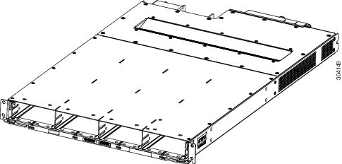
The LCC power system is made up of six AC or DC power trays that contain AC or DC PMs.
Basic Chassis Power Information
The Cisco NCS 6008 LCC can be configured with either an AC input power system or a DC input power system. Site power requirements differ, depending on the source voltage used.
For information about power safety requirements, see the Regulatory Compliance and Safety Information for the Cisco Network Convergence System 6000 Series Routers guide.
Follow these precautions and recommendations when planning power connections to the LCC:
-
Check the power at your site before installation to ensure that you are receiving clean power (free of spikes and noise). Install a power conditioner, if necessary.
-
Install proper grounding to avoid damage from lightning and power surges.
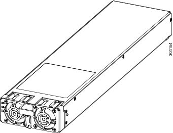
There are two types of power trays: an AC tray and a DC tray. An AC power tray houses up to three AC PMs, while a DC power tray houses up to four DC PMs. It is required that you use only one type of power tray, either AC or DC, in a LCC at a time.
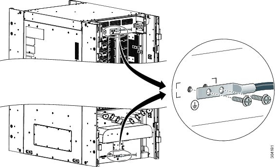
Bonding and Grounding Guidelines
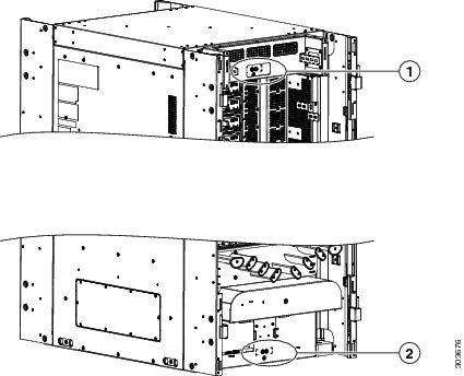
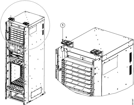
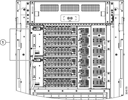
The LCC has two safety earth ground connections. The LCC allows you to connect the central office ground system or interior equipment grounding system to either of the two grounding points on the rear side of the LCC. Threaded ground inserts are located on a rear panel near the top of the LCC (above the power trays) and near the bottom of the LCC. The grounding points are also referred to as Network Equipment Building System (NEBS) bonding and grounding points.
|
1 |
NEBS bonding and grounding point (upper) |
2 |
NEBS bonding and grounding point (upper) |
 Note |
These bonding and grounding receptacles are provided to satisfy the Telcordia NEBS requirements for bonding and grounding connections. |
 Caution |
Do not remove the LCC ground cable unless the LCC is being replaced. |
AC Power System
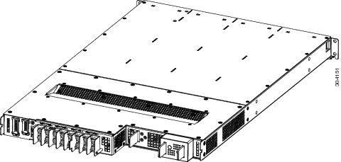
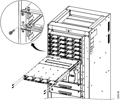
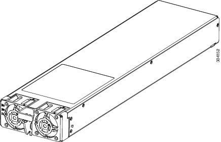
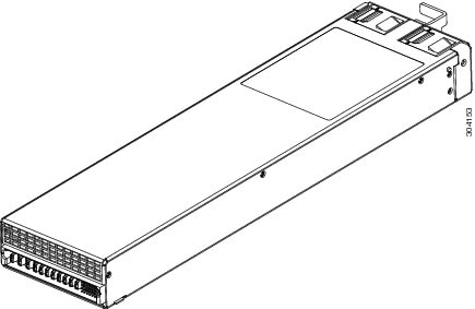
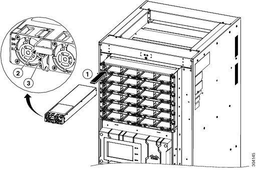
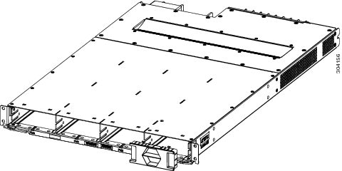
Each AC-powered LCC contains six AC power trays. The upper three AC power trays are contained within power shelf 0 (PS0), and the lower three AC power trays are contained within power shelf 1(PS1). Each power shelf has a Power bus Control Module (PCM) with its own 1/0 power switch. Each AC power tray can contain up to three AC PMs. The AC power trays and PMs are field replaceable.
Each inserted AC PM requires a single-phase, 50 to 60 Hz, 200 to 240 VAC input. Input current is variable and based on facility minimum voltage. For N+N redundancy, power feeds A must power the upper three AC power trays and power feeds B must power the lower three AC power trays. Not all of the PM bays need to be filled.
The AC power system requires single-phase AC input power to each inserted PM. If you have 3-phase AC Delta or AC Wye at your equipment, a Cisco NCS power distribution unit (PDU) is required to convert 3-phase AC input power to single-phase AC input power system.
Note |
If you have a 3-phase AC PDU installed, we recommend that you install three AC PMs in each AC power tray to maintain a balanced 3-phase power load. |
Note |
We recommend that you use appropriate short-circuit protection in compliance with national and local electrical codes. |
AC Power Distribution Unit
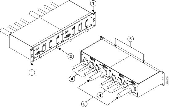
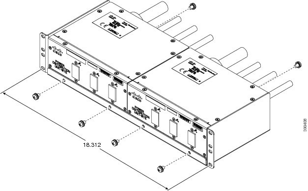
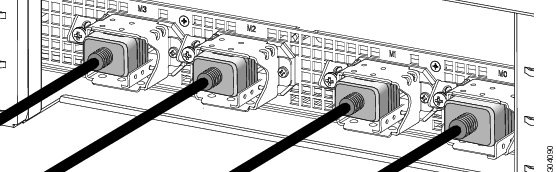
The AC PDU converts 3-phase AC input power to single-phase AC input power that connects directly to the rear of each PM. The AC PDU includes either an AC Delta (NCS-PDU-DELTA) or AC Wye (NCS-PDU-WYE) power interface, and has power input and power output cords entering and exiting the box.
|
1 |
Rack mounting ears |
4 |
Output cord |
|
2 |
Rack tray |
5 |
Two PDUs |
|
3 |
Input cord |
For detailed information on AC PDUs, see the Cisco CRS 3-Phase AC Power Distribution Unit Installation Guide .
Mounting the AC PDU
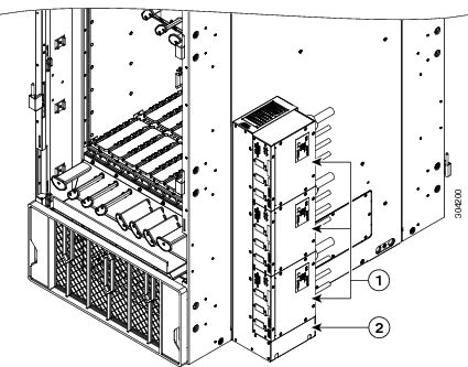
The AC PDU mounting bracket holds three AC PDUs. An AC PDU mounting bracket can be attached to the left and right sides of the LCC. The mounting brackets are attached to the chassis sides with the existing screws that hold the side panels on. The PDUs are attached to the mounting brackets with four M5 screws per AC PDU.
|
1 |
AC PDUs |
|
2 |
Bracket |
Optionally, you can mount the AC PDU in an external 19-inch rack by using six pan-head screws.
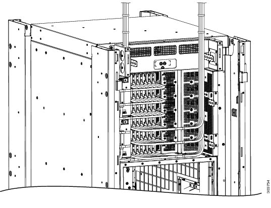
Tie-Down Bar and Cable Clamps
A 19-inch tie-down bar can be used to add strain relief for input power cables from the AC PDUs or cables routed from a raised floor. The following figure shows holes for two 10-32 x 0.50 inch screws that are pre-drilled on the top cap for attaching a tie-down bar.
Optionally, you can install cable clamps on the top of the LCC to secure multi-fiber cables to the LCC. We recommend installing two cable clamp brackets with two stacked clamps on each bracket (four clamps for each trough), however you can configure the number of clamps according to your configuration.
Note |
The tie-down bar and cable clamps are not supplied by Cisco. You can order these parts from a commercial vendor such as Panduit (see http://www.panduit.com). |
|
1 |
Cable clamps |
DC Power System
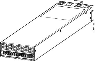
Each DC-powered LCC contains six DC power trays. The upper three DC power trays are contained within power shelf 0, and the lower three DC power trays are contained within power shelf 1 (Each power shelf has a PCM with its own 1/0 power switch) Each DC power tray can contain up to four DC PMs. The DC power trays and PMs are field replaceable.
For N+N redundancy, power feeds A must power the upper three DC power trays and power feeds B must power the lower three DC power trays. Not all of the PM bays need to be filled.
This table lists the DC input current and voltage specifications.
|
Nominal input voltage |
–48 VDC or –60 VDC (tolerance range: –40 to –72 VDC) |
|
Input line current |
50 A maximum at –48 VDC 40 A maximum at –60 VDC 60 A maximum at –40 VDC |
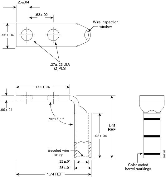
Each wiring block on the DC power tray contains two sets of terminals, one positive and one negative, and is covered by a plastic terminal block cover that is secured by a screw to a torque of 5 to 7 in-lb (0.56 to 0.79 N-m). Each DC power cable is connected to a power tray with a torque of 45 to 55 in-lb (5.1 to 6.2 N-m). The terminal block supports 2-6-AWG input wire.
The cable should be sized according to local and national installation requirements. Use only copper cable.
Note |
An “allpole” separation of the power source is not required. The DC PM is an isolated DC/DC converter with no galvanic connection between “L+” and the LCC. In addition, the “L+” potentials of each PM are isolated from each other. |
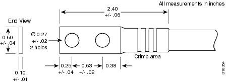
The power supply terminal posts are centered 0.63 inches (16 mm) apart and are 1/4-20 thread. We recommend that you use an appropriately sized 90-degree angle, industry-standard, dual-hole, standard barrel compression lug.
DC Input-Power-Present LEDs
The DC input-power-present LED provides a visual indication that there is voltage present across the input terminal connection. The DC input-power-present LED starts to light up when the input voltage reaches –20 VDC, gets brighter as the voltage increases, and is fully lit when the input voltage reaches –48 VDC.
Note |
Power should be disconnected before servicing the input power connection. |
Caution |
If the input voltage polarity is reversed, or if the LED circuit fails, the LED will not light. In this case, service personnel should check for hazardous voltages before working on the system. |
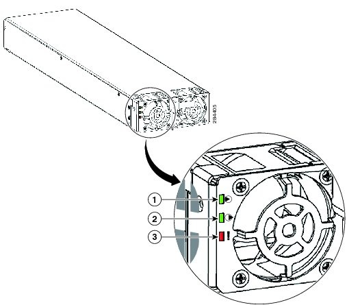
|
1 |
Input OK LED |
ON when input voltage is present and within the correct range |
|
2 |
Output OK LED |
ON when output voltage is present |
|
3 |
Fault LED |
ON when an internal fault has occurred on the PM |
AC Input-Power-Present LEDs
The AC input-power-present LED provides a visual indication that there is voltage present across the input terminal connection. The AC input-power-present LED lights up when the input voltage reaches within the acceptable range.
Note |
Power should be disconnected before servicing the input power connection. |
|
1 |
Input OK LED |
ON when input voltage is present and within the correct range |
|
2 |
Output OK LED |
ON when output voltage is present |
|
3 |
Fault LED |
ON when an internal fault has occurred on the PM |
 Feedback