Chassis Overview

This chapter provides an overview of the Cisco NCS 6008 Line Card Chassis.

Chassis Overview

The Cisco NCS 6008 LCC is a single-chassis system that provides 8 Tbps of full-duplex network bandwidth through eight line cards. Each card delivers up to 1 Tbps throughput using a mix of 10-Gbps or 100-Gbps interfaces per card. The Cisco NCS 6008 LCC also provides modular optics options to meet a wide range of distance requirements. In a back-to-back configuration, the LCC can be expanded to support up to 16 Tbps of full-duplex forwarding throughput. In a multi-chassis configuration, the LCC can be expanded to support up to 128 Tbps of full-duplex forwarding throughput.

The Cisco NCS 6008 LCC is a highly scalable routing system with redundancy and reliability features that allow for nonstop operation even during service upgrades of equipment, with no single points of failure in hardware or software. The routing system has the potential to expand from a single-chassis to a back-to-back or multi-chassis configuration for even greater routing capacity. For information about setting up a back-to-back and multi-chassis configurations, refer to the Cisco Network Convergence System 6000 Series Routers Migration Guide.

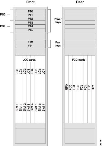
The LCC contains a chassis midplane and packet interfaces on line cards cross-connected to each other through a switch fabric. The chassis has eight slots at the front for Line Cards (LCs), two slots at the rear for Route Processor (RP) cards, and six slots at the rear for Fabric Cards (FCs).

The LCC has an integrated rack and does not require an external rack. It is bolted to the facility floor. It contains its own power and cooling systems. Power systems are available using AC or DC power.


Note

The installation of a Cisco NCS 6008 LCC may require space, floor loading, power, and cooling modifications to a facility. Therefore, you should plan the site well in advance of the scheduled delivery of the chassis system. For site preparation information, see the Cisco Network Convergence System 6000 Series Routers Site Planning Guide.

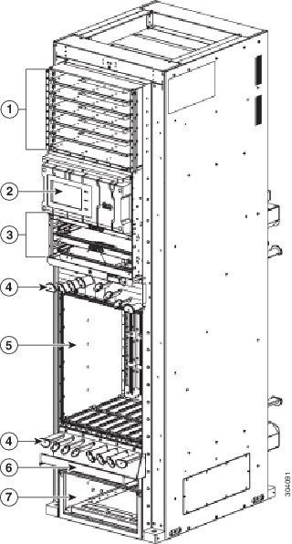
The following figure shows the front view of the Cisco NCS 6008 LCC.

Figure 1. Front View of the Cisco NCS 6008 LCC

1

Six power trays

5

One card cage with eight LC slots

2

Craft panel display

6

Air filter access

3

Two fan trays

7

Air inlet plenum

4

Cable management brackets

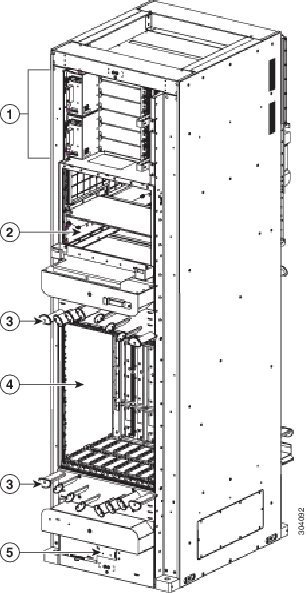
The following figure shows the rear view of the Cisco NCS 6008 LCC.

Figure 2. Rear View of the Cisco NCS 6008 LCC

1

Power input feeds (AC or DC)

4

One card cage with slots for FCs and RP cards

2

Air exhaust plenum

5

Temperature sensor

3

Cable management bracket

Chassis Components

The following table lists the main components of the Cisco NCS 6008 LCC. It identifies the components that are considered field replaceable units (FRUs), but where additional detail is useful, identifies sub-assemblies that are not field replaceable.

Table 1. Main Components of the Cisco NCS 6008 LCC

Component

Description

Chassis midplane

The chassis midplane distributes power and provides management, control, and data interconnections for other components in the system. Each LC is connected through the midplane to the FCs. The midplane is not field replaceable by the user.

Route Processor (RPs) Card

Two RP cards (RP0/RP1) are inserted into the rear of the LCC (Figure 2). These cards provide the intelligence of the system by functioning as the system controller and providing route processing and chassis management. The RP cards also monitor system alarms and control the system fans. The LEDs on the front panel indicate active alarm conditions.

Line Cards (LCs)

Up to eight LCs can be inserted into the front of the LCC (#__). These cards provide the physical interfaces and optical connections for the user data.

Fabric Cards (FCs)

Six FCs are inserted into the rear of the LCC (Figure 2). The FCs provide the switch fabric for the routing system and performs the cross-connect function of the routing system, connecting every LC to each other. The switch fabric receives ingress user data from one LC slot and performs the switching necessary to route the data to the appropriate egress LC slot.

Fan Trays

Two redundant fan trays are inserted into the front of the LCC (Figure 1). Each fan tray contains six axial fans. The fans pull cooling air through the chassis from the bottom front to top rear.

See the "About the Fan Trays" section for information on the fan trays.

Air Filter

A removable air filter is located at the bottom of the LCC, below the card cage, and inside the front air intake (Figure 1).

Power Trays

Six power trays provide redundant power to the LCC (Figure 1). Both AC and DC power trays are available. Each AC power tray has three slots for AC PMs. Each DC power tray has four slots for DC PMs. Mixing AC and DC power supplies is not supported.

The power trays are field-replaceable (after power down). The PMs are hot-swappable.

Cable management brackets

The LCC has cable management features on the front and rear sides of the chassis. These brackets organize the interface cables entering and exiting the different cards, keeping them out of the way and free of sharp bends that may damage the cables. Four horizontal cable management brackets are preinstalled on the LCC (two on the front side and two on the rear side of the LCC (Figure 1 and Figure 2).

Cable troughs

Four vertical cable troughs for cable management (two on the front-side and two on the rear-side of the LCC) and Figure 1 and Figure 2.

Temperature sensor assembly

A temperature sensor is located on the lower rear side of the LCC (Figure 2).

Craft panel display

A craft panel display, located on the front of the LCC (Figure 1), consists of an LCD touch-screen display and LEDs used to indicate system alarms. The craft panel has a basic interface used to monitor the operation of the LCC.

Chassis Cable Management

The distribution of the slot locations on the Cisco NCS 6000 LCC allows for the large number of optic fiber cables required for a fully-loaded routing system.

The NCS 6000 LCC cable management features include:

  • Front and rear cable management brackets: One cable management bracket is located above the upper card cage and one cable management bracket below the lower card cage (Figure 1 and Figure 2).
  • Vertical cable troughs: Four troughs, two on the front side of the LCC, and two on the rear side of the LCC (Figure 3-3 and Figure 3-9 ).

Slot Numbers-Front and Rear Side

The following figure the slot numbers on the front (LC) side and rear (RP and FC) side of the LCC.

Figure 3. Cisco NCS 6008 LCC Slot Numbers-Front and Rear Side


Front of the LC

The front (LC) side of the LCC has the following card slots:

  • Eight LC slots (left to right: 0, 1, 2, 3, 4, 5, 6, 7).

  • Two fan trays for redundancy. The fan trays are accessed from the front side of the LCC.

  • Six power trays for redundancy.

The upper three power trays (0-2) are contained within power shelf 0 (PS0), and the lower three power trays (3-5) are contained within power shelf 1 (PS1).

Rear of the LC

The rear side of the LCC has the following card slots:

  • Two RP card slots (RP0 on the far left of the LCC and RP1 on the far right)

  • Six FC slots (left to right: 0, 1, 2, 3, 4, 5)

The FC slots can be populated with FCs for a standalone configuration, a back-to-back configuration, or a multi-chassis configuration.

Safety Guidelines

Before you perform any Cisco NCS 6008 LCC installation procedures, review the safety guidelines in this section to avoid injuring yourself or damaging the equipment.


Note

Review the safety warnings listed in the Regulatory Compliance and Safety Information for the Cisco Network Convergence System 6000 Series Routers before installing, configuring, or troubleshooting any installed card.

Note

Power off the system before removing or installing a power tray.

The following guidelines are for your safety and to protect equipment. The guidelines do not include all hazards. Be alert.

  • Never attempt to lift an object that might be too heavy for you to lift by yourself.

  • Keep the work area clear and dust-free during and after installation. Do not allow dirt or debris to enter into any laser-based components.

  • Keep tools and chassis components away from walk areas.

  • Do not wear loose clothing, jewelry, and other items that could get caught in the chassis while working with the chassis and its components.

  • Use Cisco equipment in accordance with its specifications and product-usage instructions.

  • Do not work alone if potentially hazardous conditions exist.

  • Make sure your installation follows national and local electrical codes: in the United States, National Fire Protection Association (NFPA) 70, United States National Electrical Code; in Canada, Canadian Electrical Code, part I, CSA C22.1; in other countries, International Electrotechnical Commission (IEC) 60364, part 1 through part 7.

  • Connect only a DC power source that follows the safety extra-low voltage (SELV) requirements in UL/CSA/IEC/EN 60950-1 and AS/NZS 60590 to the DC input power system.

  • Make sure that you have a readily accessible two-poled disconnect device incorporated in the fixed configuration wiring of a DC input power system.

  • Make sure that you provide short-circuit (overcurrent) protection as part of the building installation.

Preventing Electrostatic Discharge

Electrostatic discharge (ESD) damage, which can occur when electronic cards or components are improperly handled, results in complete or intermittent failures. We recommend use of an ESD-preventive wrist strap whenever you handle network equipment or one of its components.

Following are guidelines for preventing ESD damage:

  • Always use an ESD-preventive wrist or ankle strap, and ensure that it makes good skin contact. Connect the equipment end of the connection cord to an ESD connection socket (Figure 1) or a bare metal surface on the LCC (ensure that the LCC is grounded).

  • Handle a card by its ejector levers, when applicable, or its metal carrier only; avoid touching the board or connector pins.

  • Place a removed card board side up on an antistatic surface or in a static-shielding bag. If you plan to return the component to the factory, immediately place it in a static-shielding bag.

  • Avoid contact between a card and clothing. The wrist strap protects the board from only ESD voltage on the body; ESD voltage on clothing can still cause damage.

The following figure shows an example of an ESD jack on the front side of the LCC. An ESD jack is located directly above the upper and lower cable management brackets on both sides of the LCC.

Figure 4. ESD Jack—Front Side of the LCC

1

ESD jack (two on each side of the LCC)