Cisco CRS 4-Slot
Line Card Chassis Overview
This guide describes how to plan and prepare your facilities for the delivery and installation of a Cisco CRS Carrier Routing System 4-Slot Line Card Chassis (LCC). Because the installation of the LCC may require space, rack-mounting, power, and cooling modifications to a facility, site planning should be done in advance of the scheduled delivery of the chassis.
Cisco CRS 4-Slot Line Card Chassis Overview
This chapter describes the Cisco CRS 4-slot LCC and its main components. The following sections are included:
 Note | Throughout the remainder of this guide, the Cisco CRS Carrier Routing System 4-Slot LCC is referred to as the Cisco CRS 4-slot LCC. |
The Cisco CRS 4-slot LCC documentation set is workflow-based. There are three core documents that describe the processes required to successfully plan for and install the chassis:
See (add xref) for a complete listing of Cisco CRS 4-slot LCC documentation.
-
Cisco CRS Carrier Routing System 4-Slot Line Card Chassis Site Planning Guide (this guide)
Use this guide in advance of receiving the chassis to confirm that you have the needed space, tools, utilities, manpower, etc. that are needed to perform the steps in the unpacking, moving, and securing guide and the installation guide.
-
Cisco CRS Carrier Routing System 4-Slot Line Card Chassis Unpacking, Moving, and Securing Guide
This guide is included with the chassis shipment. It includes all Cisco CRS 4-slot LCC unpacking, moving, and securing information.
-
Cisco CRS Carrier Routing System 4-Slot Line Card Chassis Installation Guide
This guide is used to initially install the chassis and describes how to remove and install field replaceable units (FRUs).
See (add xref) for a complete listing of Cisco CRS 4-slot LCC documentation.
Hardware Overview
The Cisco CRS router is a highly scalable routing platform designed for efficient service-provider point-of-presence (POP) evolution as the IP network grows into a multiservices network. The Cisco CRS router is available in 4-slot, 8-slot, 16-slot, and multishelf configurations.
The introduction of the Cisco CRS 4-slot LCC allows service providers to utilize the power and features of a Cisco CRS chassis, but without the space and power requirements associated with the larger versions of the chassis. The Cisco CRS 4-slot LCC is a mechanical enclosure that contains four slots for modular services cards (MSCs) or forwarding processor (FP) cards, and associated physical layer interface modules (PLIMs), plus four slots for the switch fabric cards (SFCs).
The router is built around a scalable, distributed three-stage Benes switch fabric and variety of data interfaces. The data interfaces are contained on physical layer interface modules (PLIMs) that are mated in the Cisco CRS 4-slot LCC to an associated MSC or FP. MSCs and FPs, which are also referred to as line cards, are cross-connected to each other through the switch fabric.
The Cisco CRS 4-slot LCC is installed in a standard external rack and contains its own power and cooling systems. The chassis also contains route processor (RP) cards that perform routing-protocol calculations. The RPs distribute forwarding tables to the modular services cards MSCs, provide a control path to each MSC and FP for system monitoring functions, and contain hard disks for system and error logging. RPs plug into two dedicated slots in the Cisco CRS 4-slot LCC.
Note | The Cisco CRS 4-slot LCC is described in greater detail in the Cisco CRS Carrier Routing System 4-Slot Line Card Chassis System Description . |
Chassis Components
This section lists the main components of the Cisco CRS 4-slot LCC. It primarily identifies the components that are considered field-replaceable units (FRUs). Where additional detail is useful, it also identifies subassemblies that are not field replaceable.
The Cisco CRS 4-slot LCC contains the following components:
- Up to four MSCs (or FPs)and four PLIMs. An MSC (or FP) and a PLIM are an associated pair of cards that mate through the chassis midplane. The line card (MSC or FP) provides the forwarding engine for Layer 3 routing of user data, and the PLIM provides the physical interface and connectors for the user data.
Three versions of MSC exist (CRS-MSC, CRS-MSC-B, and CRS-MSC-140G). There are two versions of forwarding processor (FP) cards (CRS-FP40 and CRS-FP-140).
Each MSC and FP can be associated with several different PLIMs, which provide different interface speeds and technologies. The PLIM types available are:
For complete PLIM information, see the following documents:
-
- Cisco CRS Carrier Routing System Packet-over-SONET/SDH Physical Layer Interface Module Installation Note
- Cisco CRS Carrier Routing System Ethernet Physical Layer Interface Module Installation Note.
- Optional interface solution (to PLIMs) is also available. SPA interface processors (SIPs) and shared port adapters (SPAs) can be installed instead of PLIMs. An SIP is a carrier card that is similar to a PLIM and inserts into a Cisco CRS 4-slot LCC slot and interconnects to an MSC like a PLIM. Unlike PLIMs, SIPs provide no network connectivity on their own. An SPA is a modular type of port adapter that inserts into a subslot of a compatible SIP carrier card to provide network connectivity and increased interface port density. An SIP can hold one or more SPAs, depending on the SIP type and the SPA size. POS/SDH and Gigabit Ethernet SPAs are available. For complete SIP and SPA information, see the Cisco CRS Carrier Routing System SIP and SPA Hardware Installation Guide.
- Chassis midplane. The midplane connects MSCs to their associated PLIMs and allows an MSC to be removed from the chassis without having to disconnect the cables that are attached to the associated PLIM. The midplane distributes power, connects the MSCs or GFPs to the switch fabric cards (SFCs), and provides control plane interconnections. The midplane is not field replaceable by the customer.
- Two RP cards. The RPs provide the intelligence of the system by functioning as the Cisco CRS 4-slot LCC system controller and performing route processing. Only one RP is active at a time. The second RP acts as a standby RP, serving as a backup if the active RP fails. The RP also monitors system alarms and controls the system fans. LEDs on the front panel indicate active alarm conditions.
A Performance Route Processor (PRP) is also available for the Cisco CRS 4-slot line card chassis. Two PRPs perform the same functions as RPs, but provide enhanced performance for both route processing and system controller functionality.
Note | A chassis may not be populated with a mix of RP and PRP cards. Both route processor cards should be of the same type (RP or PRP). |
- Four SFCs. These cards provide a three-stage Benes switch fabric for the system. The switch fabric receives user data from one line card (MSC or FP) and PLIM pair and performs the switching necessary to route the data to the appropriate egress line card and PLIM pair. The Cisco CRS 4-slot LCC SFCs provide all three stages of the three-stage Benes switch fabric.
- One AC power shelf with four AC rectifiers in each power shelf. The power shelf and AC rectifiers provide 4,000 watts of redundant input power for the chassis.
- One DC power shelf with four DC power supplies. The DC power system provides 4,000 watts to power the chassis.
- Fan tray. The fan tray contains fans that push and pull air through the chassis. A removable air filter is located above the power shelf in the front of the chassis.
The front of the chassis contains the RPs, MSCs, FPs, and PLIMs. This is where user data cables attach to the PLIMs and where cool air enters the chassis. The rear of the chassis contains the fan tray and the SFCs.
The figure below and Figure 2 show the front and rear views of the Cisco CRS 4-slot LCC.
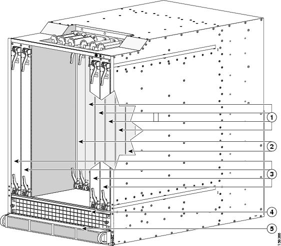
|
1 |
PLIM slots |
4 |
Air intake |
|
2 |
RP slots |
5 |
Power supplies |
|
3 |
MSC slots |
|
|

|
1 |
Fan tray |
2 |
Switch fabric card (half-height) slots |
|
3 |
AC input power receptacles and power switches |
|
|
Overview of Site Planning Steps
Table 1 lists the steps required to prepare your site for the delivery and installation of a Cisco CRS 4-slot line card chassis. For information about a particular task, see the appropriate chapter or section of this site planning guide.
See the Appendix Preliminary Site Survey for a sample of the preliminary site survey that you should complete before you prepare a detailed site survey.
|
Site Planning Steps |
See |
Check |
|---|---|---|
|
1. Confirm that the chassis delivery site meets delivery space requirements |
|
|
|
2. Determine and gather the required unpacking tools. |
|
|
|
3. Determine the route from the delivery site to the installation site and confirm space and manpower needs. |
|
|
|
4. Determine and gather the required moving tools. |
|
|
|
5. Confirm that the installation site meets basic space requirements. |
|
|
|
6. Confirm that the installation site meets basic power and grounding requirements. |
|
|
|
7. Confirm that the installation site meets basic cooling and airflow requirements. |
"Environmental Specifications" section |
|
|
8. Confirm that the installation site meets basic cooling and airflow requirements. |
|
 Feedback