Cisco CRS Carrier Routing System 4-Slot Line Card Chassis Site Planning Guide
Bias-Free Language
The documentation set for this product strives to use bias-free language. For the purposes of this documentation set, bias-free is defined as language that does not imply discrimination based on age, disability, gender, racial identity, ethnic identity, sexual orientation, socioeconomic status, and intersectionality. Exceptions may be present in the documentation due to language that is hardcoded in the user interfaces of the product software, language used based on RFP documentation, or language that is used by a referenced third-party product. Learn more about how Cisco is using Inclusive Language.
- Updated:
- October 27, 2016
Chapter: Planning for Delivery
Planning for
Delivery
This chapter describes the site planning steps related to the delivery of the Cisco CRS 4-Slot LCC.
 Note | The topics in this section are for general planning purposes only. The tasks involved are covered in detail in the Cisco CRS Carrier Routing System 4-Slot Line Card Chassis Unpacking, Moving, and Securing Guide that is shipped with the LCC. |
The following sections are included:
Planning for Delivery
This chapter describes the site planning steps related to the delivery of the Cisco CRS 4-Slot LCC. The following sections are included:
Note | The topics in this section are for general planning purposes only. The tasks involved are covered in detail in the Cisco CRS Carrier Routing System 4-Slot Line Card Chassis Unpacking, Moving, and Securing Guide that is shipped with the LCC. |
Planning to Receive the Chassis
Before installing the LCC, it must be received at your shipping dock or other delivery location. This section provides the specifications that your shipping and receiving team may find useful prior to delivery of the LCC.
Chassis Dimensions and Weights
The two most important factors in planning for the delivery of the LCC are the chassis dimensions and weights (both packaged and unpackaged). The table below provides the dimensions and weight of a packaged LCC. Table 2 provides the dimensions and weight of an unpackaged LCC.
|
Weight |
338 lb (153.3 kg)—Chassis including packaging and pallet |
|---|---|
|
Dimensions |
Height: 42 in. (106.6 cm) Width: 24.5 in. (62.2 cm) Length: 39.75 in. (100.9 cm) |
|
Weight |
260 lb (118 kg)—As shipped with fan tray, power shelf, and card slot blanks 380 lb (172 kg)—Total weight with all SFCs, MSCs, PLIMs, and RPs installed |
|---|---|
|
Dimensions |
Height: 30 in. (76.2 cm) Width: 17.65 in. (44.8 cm)—Without cosmetics Depth: 30.28 in. (76.9 cm) |
Planning to Unpack the Chassis
To unpack the chassis, you need space, tools, and sufficient manpower. Use the specifications in Table 1 to determine how much space and manpower you need to unpack a packaged chassis.
Required Unpacking Tools
The following tools are required to unpack the chassis:
- Medium (Number 2) Phillips screwdriver
- 9/16-inch (15 mm) socket wrench
- Scissors or wire cutters
- ESD-preventive wrist strap
- Antistatic mat or bag
Note | Removing the packaging prior to moving the Cisco CRS 4-slot LCC is optional. The packaging can be removed either at the loading dock or at the installation site. However, we recommend unpacking the chassis at the installation site (if feasible) to reduce the possibility of damage to the chassis. |
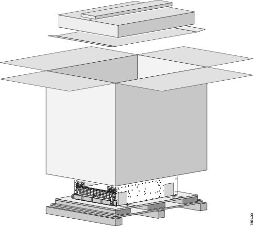
Shipping Crate and Pallet
The LCC is shipped on a pallet and arrives inside a polyethylene bag enclosed in a box, held in place by plastic bands (see the below figure). For complete details on the contents of each crate, see the shipping and parts identification label on the crate.
 Caution | Do not stack the LCC shipping crate, becaue serious damage to the chassis can occur. |
Unpacking Considerations
Consider the following as you plan for unpacking the chassis:
- Make sure that enough room exists at the loading dock or installation site to unpack the chassis. If you plan to store the chassis before installation, make sure that you have a large enough area. You should store the chassis in its shipping crate until you are ready to install it.
- Determine if you are going to unpack
the chassis at the loading dock or installation site. Consider the following:
- Are the corridors and aisles from the loading dock to the installation site wide enough for the moving device and the chassis packed in its crate? (See Table 1.) If not, consider unpacking the chassis at the loading dock.
- If corridors and aisles are wide enough and there is enough space at the installation site to unpack the chassis, we recommend leaving the chassis in its packaging during the move.
- If the corridors and aisles are not wide enough, the packaging needs to be removed at the loading dock. Doing so makes the chassis shorter and narrower while remaining on the pallet.
- Consider how you will move the chassis components from the shipping dock to the installation site.
Planning to Move the Chassis
As with unpacking, moving the LCC from the loading dock requires space, tools, and manpower. Use the specifications in Table 1 and Table 2 to determine how much space and manpower you will need to move the chassis.
Required Moving Tools
The following tools are required to move the chassis:
- Mechanical lifting device with a lifting capacity exceeding 500 lb (227 Kg).
- Piece of cardboard roughly the width of the chassis.
Moving Considerations
When planning your LCC installation, you must consider how the chassis will be moved from the shipping dock to the site where the chassis is to be installed. This section provides information about the things to consider as you plan for transportation of the chassis from the loading dock to the installation site.
The line card chassis is shipped in a crate that reduces the potential for product damage during routine material handling and shipment. To protect the chassis:
- Transport the chassis in its original packaging whenever possible, and make sure that the chassis is transported and stored in an upright position.
- If you plan to store the chassis before the installation, leave it in its original shipping container to prevent accidental damage.
Consider the route you intend to use to move the chassis from the loading dock to the installation site. See Table 1 for the minimum hallway, aisle, and doorway clearances required to accommodate the chassis.
Before you attempt to move the chassis to the installation site, we recommend that you check the proposed transport route and note any areas of concern. It might also be useful to create a diagram of the route you plan to take from the loading dock to the installation site.
Note | We recommend that at least two people move the chassis from the shipping dock to the installation site. |
- Is the installation site on a different floor than the loading dock? If so, are there freight elevators that can be used to transport the chassis?
- Are there any ramps in the transport route? If so, does the ramp create an incline that impedes transportation of the chassis on its pallet?
- Are there any raised floors in the transport route or at the installation site that need to be protected while you move the chassis?
- Make sure that hallways, aisles, and doorways are high and wide enough to accommodate the chassis and moving device (for example, forklift). See Table 1 for packaged chassis dimensions.
- Make sure that corners are wide enough for the chassis and moving device.
- Make sure that no obstacles exist in the transport route (for example, boxes or equipment in hallways, hanging wires, items on the floor, and so on).
- Determine what type of moving device you will use (such as a forklift or similar moving device) to move the chassis. The following section describes the things to consider about a moving device:
Using a Forklift to Move the Chassis—Things to Consider
If you plan to use a forklift or similar moving device (such as a safety hand truck or pallet jack) to move the chassis, consider the following:
It must be capable of preventing the chassis from tipping. For example, you could use a safety hand truck with retractable safety leg wheels and a security strap.
We recommend that you leave the chassis in its shipping crate and pallet for moving.
Make sure that the moving device can support the weight of the chassis and its shipping crate (see Table 1).
Make sure that hallways and doorways (including elevators) are high and wide enough for the shipping crates and moving device. See Table 1 for packaged chassis dimensions.
Verifying the Move Path
Before moving the chassis, it is critical that you verify that the path that you are planning to use to move the chassis to its final location can accommodate the chassis size and weight and the restrictions of the chassis when using the moving device.
See the table below for a list of the restrictions for your move path, and verify that you have sufficient room for the entire move path prior to moving the chassis.
|
Description |
Value |
|---|---|
|
Height |
30 in. (76.2 cm) |
|
Depth |
30.3 in. (77 cm) |
|
Width |
18.5 in. (47 cm) |
|
Weight of chassis as shipped |
338 lb (153.3 kg) |
|
Maximum incline |
10 degrees |
|
Maximum curb height |
1.00 in. (2.54 cm) |
Note | These specifications include a gap of 6 in. (15 cm) on each side of the chassis to facilitate moving the chassis. |
 Feedback