Cisco CRS Carrier Routing System 4-Slot Line Card Chassis Site Planning Guide
Bias-Free Language
The documentation set for this product strives to use bias-free language. For the purposes of this documentation set, bias-free is defined as language that does not imply discrimination based on age, disability, gender, racial identity, ethnic identity, sexual orientation, socioeconomic status, and intersectionality. Exceptions may be present in the documentation due to language that is hardcoded in the user interfaces of the product software, language used based on RFP documentation, or language that is used by a referenced third-party product. Learn more about how Cisco is using Inclusive Language.
- Updated:
- October 27, 2016
Chapter: Planning for Installation
Planning for
Installation
This chapter describes how to plan for the installation of the Cisco CRS 4-slot line card chassis (LCC).
 Note | The Cisco CRS Carrier Routing System 4-Slot Line Card Chassis Unpacking, Moving, and Securing Guide ships with your chassis and is the most up-to-date resource for unpacking and moving the chassis, and securing it to its operational location. |
The following sections are included:
Planning for Installation
This chapter describes how to plan for the installation of the Cisco CRS 4-slot line card chassis (LCC). The following sections are included:
Note | The Cisco CRS Carrier Routing System 4-Slot Line Card Chassis Unpacking, Moving, and Securing Guide ships with your chassis and is the most up-to-date resource for unpacking and moving the chassis, and securing it to its operational location. |
- Required Securing and Installation Tools
- Planning for Safety
- Planning for Space
- Planning for Power
- Planning for Cooling
- Planning for Cabling
Required Securing and Installation Tools
The following tools are required to secure and install the Cisco CRS 4-slot LCC:
- ESD-preventive wrist strap
- Large flat-blade screwdriver
- Medium flat-blade screwdriver
- Small flat-blade screwdriver
- Large (Number 3) Phillips screwdriver
- Medium (Number 2) Phillips screwdriver
- Small (Number 1) Phillips screwdriver
- 4-mm socket wrench
Planning for Safety
Before planning any aspect of the Cisco CRS 4-slot LCC installation, review the following general safety guidelines. This list is not inclusive of all potentially hazardous situations, so be alert.
- General Safety Guidelines
- Compliance and Safety Information
- Preventing Electrostatic Discharge Damage
- Laser Safety
- Lifting Guidelines
- Electrical Safety
General Safety Guidelines
- Never attempt to lift an object that might be too heavy for you to lift by yourself.
- Always disconnect the power source and unplug all power cables before lifting, moving or working on the chassis.
- Keep the work area clear and dust free during and after installation.
- Keep tools and chassis components away from walk areas.
- Do not wear loose clothing, jewelry (including rings and chains), or other items that could get caught in the chassis.
- Fasten ties or scarfs and sleeves.
- Check that the Cisco CRS 4-slot LCC operates safely when it is used in accordance with its electrical ratings and product usage instructions.
- Do not work alone if potentially hazardous conditions exist.
- Always unplug the power cables when performing maintenance or working on the chassis, unless the replacement part is capable of online insertion and removal (OIR).
- Confirm that the installation of your chassis is in compliance with national and local electrical codes: in the United States, National Fire Protection Association (NFPA) 70, United States National Electrical Code; in Canada, Canadian Electrical Code, part I, CSA C22.1; in other countries, International Electrotechnical Commission (IEC) 364, part 1 through part 7.
- Before installing, configuring, or maintaining the chassis, review the safety warnings listed in Cisco CRS Carrier Routing System Regulatory Compliance and Safety Information, which accompanied your chassis.
- Confirm that the AC powered Cisco CRS 4-slot LCC is shipped with a three-wire electrical grounding-type plug that fits only into a grounding-type power outlet. This is a safety feature. The equipment grounding should be in accordance with local and national electrical codes.
Compliance and Safety Information
The Cisco CRS 4-slot LCC is designed to meet regulatory, compliance, and safety approval requirements. If you require additional compliance information, see Cisco CRS Carrier Routing System Regulatory Compliance and Safety Information that is shipped with your chassis.
Preventing Electrostatic Discharge Damage
Electrostatic discharge (ESD) damage to chassis components can occur if the parts are handled improperly. Such mishandling can result in intermittent or complete failures of the equipment.
When handling any chassis components, observe the following guidelines to prevent ESD damage.
- Always use an ESD-preventive ankle or wrist strap and ensure that the strap makes adequate contact with your skin.
- The ankle or wrist strap protects equipment from ESD voltages on the body only; ESD voltages on clothing can still cause damage to electronic components.
- Use an ESD antistatic strap and follow its instructions for use.
 Caution | Periodically check the resistance value of the antistatic ankle or wrist strap. The resistance measurement should be between 1 and 10 megohms. |
Laser Safety
Physical Layer Interface Modules (PLIMs) are equipped with lasers, which emit invisible radiation. Do not stare into open PLIM ports.
Because invisible radiation may be emitted from the aperture of the port when no fiber cable is connected, avoid exposure to radiation and do not stare into open apertures. Statement 127
Lifting Guidelines
A fully configured Cisco CRS 4-slot LCC weighs approximately 361 lb. (163.7 kg). Before installing the chassis, ensure that your site is properly prepared so you can avoid having to move the chassis later to accommodate power source and network connections.
Each time you lift any heavy assembly, refer to these lifting guidelines:
- Never attempt to lift an object that might be too heavy for you to lift by yourself
- Have a second person available to help lift the assembly
- Ensure that your footing is solid; balance the weight of the object between your feet
- Lift the assembly slowly; never move suddenly or twist your body as you lift
- To prevent injury to your back, keep your back straight while lifting the shelf and lift the equipment with your legs as you stand up
- If you must bend down to lift the assembly, bend at the knees, not at the waist, to reduce the strain on your lower back muscle
- Always disconnect the power source and unplug all power cables before lifting, moving or working on the chassis
Electrical Safety
The field replaceable units (FRUs) in the Cisco CRS 4-slot LCC offer online insertion and removal (OIR) capability, which means an FRU is hot swappable and can be removed and replaced while the system is operating without presenting an electrical hazard or damage to the system.
The following FRUs feature OIR:
- MSCs, FPs, and PLIMs
- RPs—Only when two are installed in the chassis
- SFCs
- Air filter
Note | For more information on installing and removing components, see the Cisco CRS Carrier Routing System 4-Slot Line Card Chassis Installation Guide. |
Working with electrical equipment can be hazardous. Three types of potential hazards are addressed in this section.
Electric Shock Hazard
Use these guidelines if an electrical accident occurs while working with any electrical equipment.
- Disconnect power to the system, never assume that power has been disconnected from a circuit; always check.
Before assisting an injured person, make sure there is no possibility of electrical shock or other potential hazard to yourself.
- Send another person to get medical aid; otherwise, assess the condition of the victim and then call for help.
- Determine if the person needs rescue breathing or external cardiac compressions, then take appropriate action.
Equipment Hazards
Use these guidelines when working with equipment you want to install:
- Disconnect all power and external cables before installing or removing a chassis.
- Never assume that power has been disconnected from a circuit; always check.
- Do not perform any action that creates a potential hazard to people or makes the equipment unsafe.
- Never install equipment that appears damaged.
-
Carefully examine your work area for possible hazards such as:
- Moist floors
- Ungrounded power extension cables
- Missing safety grounds
Installation Hazards
Use these guidelines when working with equipment that is disconnected from a power source, but is still connected to telephone or network wiring.
- Never install telephone wiring during a lightning storm.
- Never install telephone jacks in wet locations unless the jack is specifically designed for wet locations.
- Never touch uninsulated telephone wires or terminals unless you are sure the telephone line has been disconnected at the network interface.
- Use caution when installing or modifying telephone lines.
Planning for Space
Space planning for the Cisco CRS 4-slot LCC is consistent with other chassis that install in a standard 19-inch (48-cm) Telco equipment rack. This section includes the following topics:
- Rack-Mounting Planning Guidelines
- Cisco CRS 4-Slot Line Card Chassis Footprint
- Aisle Spacing and Maintenance Access Floor Plan
Rack-Mounting Planning Guidelines
Before installing the Cisco CRS 4-slot LCC in a rack, consider the following general rack-mounting guidelines.
- As you face the rear of the chassis, the fan tray assembly is located on the top portion of the chassis. Air flow to the air inlet on the front of the chassis and the rear fan tray assembly should not be blocked.
Note | Warm air exhausts at the back of the chassis through the fan tray. Allow sufficient air flow by maintaining a minimum of 6 inches (15 cm) of clearance at the front and rear of the chassis. |
- A ventilation system that is too powerful in an enclosed rack can also prevent cooling by creating negative air pressure around the chassis and redirecting the air away from the air intake vent. If necessary, operate the chassis with the rack door open or in an open rack.
- The correct use of baffles inside an enclosed rack can assist in cooling the chassis.
- Equipment located near the bottom of the rack can generate excessive heat that is drawn upward and into the intake ports of equipment above, leading to possible overheat conditions.
Note | The rack-mounting hardware included with the Cisco CRS 4-slot LCC is suitable for most 19-inch (48-cm) equipment racks. |
- For the CRS-4-LCC to meet GR-63-CORE Zone 4 Earthquake Requirements, a 19" rack designed to withstand GR-63-CORE Zone 4 earthquakes for the intended rack weight loading must be used.
- Be sure that the rack is bolted to the floor. The chassis mounts to the two rack posts, and the rest of the chassis is cantilevered off of the posts.
- Ensure that the weight of the chassis does not make the rack unstable.
- Some racks are secured to ceiling brackets, if necessary, because of the weight of the equipment in the rack. Make sure that the rack you are installing the chassis in is secured.
- If mounting the chassis on a four-post rack, it must be recessed no more than 1.5 inches (3 cm) for the front door to fully open and close and to provide adequate room for cable routing.
Multiple Chassis in a Rack
One of the unique features of the Cisco CRS 4-slot LCC is its size. Up to two chassis can fit in a standard 19-inch (48-cm) equipment rack. When placing multiple chassis in a rack, ensure there is sufficient ventilation to accommodate both chassis.
Hot exhaust air from other equipment can enter the inlet air vents and cause an overtemperature condition inside the chassis.
- Install and use the line card brackets and the chassis cable-management bracket included with the chassis to keep cables organized and out of the way of PLIMs.
- Ensure that cables from other equipment do not interfere with access to the card cage, or require you to disconnect cables unnecessarily to perform equipment maintenance or upgrades.
- When mounting the chassis in a four-post type rack, be sure to use all of the screws provided to secure the chassis to the rack posts.
Cisco CRS 4-Slot Line Card Chassis Footprint
The figure below shows a top view of the Cisco CRS 4-slot LCC footprint. The front of the chassis is at the top of the figure.
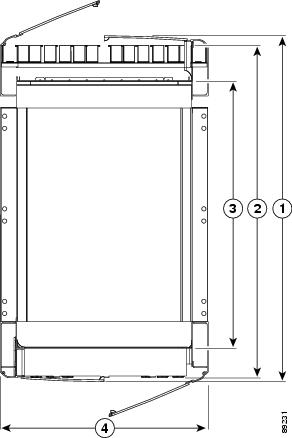
|
1 |
Depth (without cosmetic doors) 30.2 in. (76.9 cm) |
2 |
Width 18.5 in. (47.1 cm) |
Aisle Spacing and Maintenance Access Floor Plan
Make sure that enough space exists at the installation site to install the line card chassis and allow sufficient airflow. The floor plan must also provide enough room to access chassis components for maintenance (for example, to remove fan trays, power supplies, cables, and the air filter). The figure below shows a typical floor plan and the table below lists the minimum clearances required.
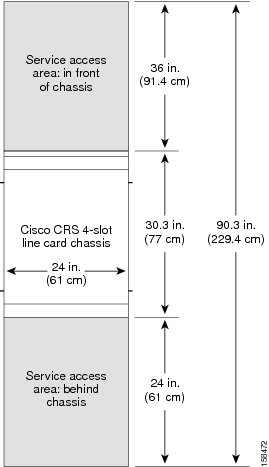
The table below lists the minimum installation and maintenance access clearances required for the chassis.
|
Type of Access |
Clearance Required |
Purpose |
|---|---|---|
|
Chassis Clearance |
||
|
Front |
36 in. (91.4 cm) |
To allow access to chassis components (for example, to access cables). |
|
Rear |
24 in. (61 cm) |
To allow access to chassis components (for example, to remove fan trays, power supplies, and air filters). |
|
Inlet and exhaust openings (chassis and power supplies) |
6 in. (15.2 cm) |
To allow sufficient airflow for chassis components. |
|
Side of chassis (left and right) |
None |
|
|
Aisle Clearance |
||
|
Aisle width |
50 in. (127 cm) |
To move the chassis through an aisle. |
|
||
|
Turn radius of chassis |
50 inches (127 cm) |
To turn the chassis. |
Note | The most up-to-date clearance requirement information is located in the Cisco CRS Carrier Routing System 4-Slot Line Card Chassis Unpacking, Moving, and Securing Guide. |
Note | For front-to-front row alignment and back-to-back row alignment: we recommend that adjacent rows of chassis align the front intake to front intake or rear exhaust to rear exhaust. |
Planning for Power
The chassis power system provides power to chassis components and is made up an AC or DC power shelf that contains four power supplies. Each power supply is connected to a separate and independent power source.
Each power supply receives input power from a different power source. The power system provides 1+1 redundancy. During normal operation, the power shelf and power supplies function together to power the chassis. However, if a power source to one or two power supplies fails, the remaining power supplies provide enough input power to power the chassis. This 1+1 redundancy enables the chassis to operate despite a limited power failure or during power supply replacement.
The Cisco CRS 4-slot LCC features a single power shelf consisting of four 2000-W AC or DC power supplies. Site requirements differ depending on the type of power source voltage.
This section includes the following topics:
Note | For additional power system details, see the Cisco CRS Carrier Routing System 4-Slot Line Card Chassis Installation Guide. |
General Power and Grounding Requirements
This section describes the power and grounding requirements you must consider when planning the site facilities for the line card chassis. In addition, see the AC Power System and the DC Power System for additional power requirements.
Note | A certified electrician should review the information in these sections to ensure that the installation site meets these requirements. For larger system configurations, you may want to consult a facilities electrical expert to understand the load that the routing system may put on the facility power plant. |
- Installation of the Cisco CRS 4-slot LCC must follow national and local electrical codes:
- In the United States—United States National Fire Protection Association (NFPA) 70 and United States National Electrical Code (NEC)
- In Canada—Canadian Electrical Code, part I, CSA C22.1
- In other countries—International Electrotechnical Commission (IEC) 60364, parts 1 through 7
- Four separate and independent AC or DC power sources are needed to provide 1+1 redundancy for system power. Each pair of power supplies has its own circuit breaker.
- Each power source must provide clean power to the site. If necessary, install a power conditioner.
- Sites must provide short-circuit (over-current) protection for devices.
- Proper grounding is required at the site to ensure that equipment is not damaged by lightning and power surges. In addition:
- For AC-powered systems, a grounding-type AC power outlet is required.
- For DC-powered systems, the installation must have a ground connection of the appropriate gauge to the DC power shelf ground lug.
- When planning power for the site, be sure to include the power requirements for any external terminals and test equipment you will use with your system.
Note | Be sure to review the safety warnings in Cisco CRS Carrier Routing System Regulatory Compliance and Safety Information. |
Site Wiring
This section offers site wiring guidelines for setting up the plant wiring and cabling at your site. When planning the location of the new system, consider the following:
- Electromagnetic interference (EMI)
- Distance limitations for signaling and unshielded conductors
Electromagnetic Interference
Electromagnetic interference can occur between the signal on the wires and external or ambient EMI fields when the wires are run for any significant distance. Bad wiring practice can result in radio interference emanating from the plant wiring.
Note | To predict and remedy strong EMI, you may need to consult experts in radio frequency interference (RFI). |
If you use twisted-pair cable in your plant wiring with a good distribution of grounding conductors, the plant wiring is unlikely to emit radio interference. If you exceed the recommended distances, use a high-quality twisted-pair cable with one ground conductor for each data signal when applicable.
Electromagnetic Pulse Considerations
Give special consideration to the effect of a lightning strike in your vicinity if wires exceed recommended distances, or if wires pass between buildings. The electromagnetic pulse (EMP) caused by lightning or other high-energy phenomena can easily couple enough energy into unshielded conductors to destroy electronic devices.
Provide a properly grounded and shielded environment, with special attention to issues of electrical surge suppression, to avoid the time loss to identify and resolve future surge and distance issues after your chassis is installed.
AC Power System
Each AC-powered line card chassis requires 4270 watts (4.27 kW) of AC input power. Two of the four 2000-watt power supplies must be functioning in order to properly power the chassis. The power supplies are 92percent efficient.
Each AC-powered chassis includes a single power shelf consisting of four power supplies. This “two and two” configuration within the single power shelf provides 1+1 redundancy. Each power supply requires one input power connection. The power shelf supports four AC-to-DC power supplies that are FRUs. The AC-to-DC power supplies convert 200 to 240 VAC power to –54 VDC used by the Cisco CRS 4-slot LCC.
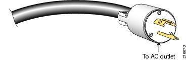
The power cables, which are 13 feet (4 m) long, are not shipped preattached to the power shelf. The figure below shows the AC power cord plug. AC power input is 2 wires + protective earthing. The gauge of the earth conductor must be equal to or larger than that of the phase conductor.
For additional power system details, see the Cisco CRS Carrier Routing System Line Card Chassis Installation Guide.
DC Power System
The Cisco CRS 4-slot LCC DC power shelf consists of two major components (see the figure below):
- DC power input shelf (Cisco product number: CRS-4-DC-INPUT)
- Power input module (PIM) (Cisco product number: CRS-4-DC-PIM)
When installing the DC power shelf, these two components are mated to create the complete DC power shelf.
The figure below shows the PIM and the DC power input shelf.
|
1 |
DC power input shelf |
2 |
Power input module (PIM) |
The Cisco CRS 4-slot LCC DC power system provides 4,000 watts to power the chassis. (To provide power redundancy, up to 8,000 watts are available.) Each DC-powered chassis contains four DC power supplies for 2N redundancy. The PIM provides the input power connections. Note that each power connection has two cables: –48 VDC and return. The PIM, DC power input shelf, and the power supplies are field replaceable.
The Cisco CRS 4-slot LCC requires a total of four dedicated pairs of 60-A DC input power connections, one pair for each of the power supplies, to provide redundant DC power to the Cisco CRS 4-slot LCC midplane.
For full 2N redundancy, we recommend that you have two independent –48 VDC power sources to provide power to the Cisco CRS 4-slot LCC. Connect the two 60-A DC inputs on the left to one wiring block, and the two 60-A DC inputs on the right to the other wiring block.
For more information, see Chapter 2, “Installing and Removing Power Components,” in the Cisco CRS Carrier Routing System Line Card Chassis Installation Guide .
Planning for Cooling
Proper air circulation and cooling are essential to ensure optimal Cisco CRS 4-slot LCC operation. This section includes information on how to plan for the environment that the chassis will be operated in. This section includes the following topics:
Environmental Guidelines
This section offers guidelines for operating your Cisco CRS 4-slot LCC in various environments. Included are airflow, temperature, and humidity recommendations. To assure normal operation and avoid maintenance difficulty, plan and prepare your site before you install the chassis.
Airflow
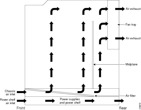
The airflow through the Cisco CRS 4-slot LCC is controlled by a push-pull configuration. The figure below shows how ambient air flows in at the bottom front of the Cisco CRS 4-slot LCC and up through the card cages until it exhausts at the top rear. The power supplies in the power shelves have their own self-contained cooling fans. The Cisco CRS 4-slot LCC has a maximum airflow of 880 cubic feet (24,918 liters) per minute.
A replaceable air filter is positioned above the power shelf. How often the air filter should be replaced depends on the facility environment. In a dirty environment, or when you start getting frequent temperature alarms, you should always check the intake grills for debris, and then check the air filter to see if it needs replacement.
Caution | Do not remove the air filter with the fan tray functioning. See the Cisco CRS Carrier Routing System 4-Slot Line Card Chassis Installation Guide for specific instructions on how to service the air filter. |
As shown in the above figure, air circulates through the card cage, and exhausts at the back of the chassis
- Allow sufficient air flow by maintaining 6 inches (15 cm) of clearance at both the front inlet and rear exhaust openings on the chassis.
- Sites should be as dust-free as possible. Dusty environments can clog the air filter, reducing the cooling airflow through the chassis. This can cause an over temperature condition in the chassis.
Under extreme environment conditions, the environmental monitoring system shuts down the power to protect the system components.
Temperature and Humidity
The operating environmental site requirements are listed in Cisco CRS 4-Slot Line Card Chassis System Specifications of the Cisco CRS Carrier Routing System 4-Slot Line Card Chassis Site Planning Guide The temperature and humidity ranges listed are those within which the chassis continues to operate. You can maintain normal operation by anticipating and correcting environmental irregularities before they approach critical values.
The environmental monitoring functionality built into the chassis protects the system and components from potential damage from overvoltage and overtemperature conditions.
Planning for Cabling
Cabling runs should be carefully planned. The basic configurations for various routing systems should be arranged to minimize the complexity and length of the cable runs. Precut and terminated cables are considered part of the basic configuration. This section includes the following topics:
Physical Layer Interface Module Cables
You must provide the MSC and PLIM interface cables. You also provide the cable management trays for these cables from the Cisco CRS 4-slot LCC to your facility interconnect. Interfaces vary with each system site, plan these data cable runs in advance of the system installation.
Chassis Cable-Management
The Cisco CRS 4-slot LCC has cable-management features for the front of the chassis. These cable-management features consist of horizontal cable-management trays above the card cage. These trays have a special telescoping feature that allows them to be extended when the chassis is upgraded with higher-density cards. This extension feature also helps in installing the cables in the chassis.
For detailed information about chassis cabling and cable management, see the Cisco CRS Carrier Routing System 4-Slot Line Card Chassis Installation Guide.
Planning for High Availability
The following is a list of tasks you can consider doing to configure the line card chassis for high availability, which helps to ensure that service is not disrupted due to failures:
- Consider installing a redundant line card chassis, whose user interface links mirror the links on the other line card chassis. This way, if something happens to one line card chassis, the links are still operational on the other line card chassis.
To provide more high availability, you can also install each line card chassis in a different room, located in a different fire and power zone. This way, a problem in one room should not affect the operation of the other chassis.
- Consider running the power cables from the power shelf along different routes through the facility or at the installation site.
- Consider running PLIM user interface cables along different routes.
 Feedback