Implementing Layer 2 Tunnel Protocol Version 3 on Cisco IOS XR Software
Available Languages
Table Of Contents
Implementing Layer 2 Tunnel Protocol Version 3 on Cisco IOS XR Software
Prerequisites for Layer 2 Tunnel Protocol Version 3
Information About Layer 2 Tunnel Protocol Version 3
Local Switching: Quality of Service
L2TPv3 Type of Service Marking
Maximum Transmission Unit Handling
How to Implement Layer 2 Tunnel Protocol Version 3
Configuring a Pseudowire Class
Configuring L2TP Control-Channel Parameters
Configuring L2TP Control-Channel Timing Parameters
Configuring L2TPv3 Control-Channel Authentication Parameters
Configuring L2TP Control-Channel Maintenance Parameters
Configuring L2TPv3 Pseudowires
Configuring a Dynamic L2TPv3 Pseudowire
Configuring a Static L2TPv3 Pseudowire
Configuring the Cross-connect Attachment Circuit
Configuration Examples for Layer 2 Tunnel Protocol Version 3
Configuring an L2TP Class for L2TPv3-based L2VPN PE Routers: Example
Configuring a Pseudowire Class: Example
Configuring L2TPv3 Control Channel Parameters: Example
Configuring the Cross-Connect Group: Example
Configuring an Interface for Layer 2 Transport Mode: Example
Implementing Layer 2 Tunnel Protocol Version 3 on Cisco IOS XR Software
Layer 2 Tunnel Protocol Version 3 (L2TPv3) is an Internet Engineering Task Force (IETF) working group draft that provides several enhancements to L2TP, including the ability to tunnel any Layer 2 (L2) payload over L2TP. Specifically, L2TPv3 defines the L2TP protocol for tunneling Layer 2 payloads over an IP core network using L2 virtual private networks (VPNs).
For additional information about L2TPv3, see Implementing MPLS VPNs over IP Tunnels on Cisco IOS XR Software.
Feature History for Implementing Layer 2 Tunnel Protocol Version 3 on Cisco IOS XR Software
Contents
•
Prerequisites for Layer 2 Tunnel Protocol Version 3
•
•
•
Prerequisites for Layer 2 Tunnel Protocol Version 3
The following prerequisites are required to implement L2TPv3:
•
•

Note
Information About Layer 2 Tunnel Protocol Version 3
To configure the L2TPv3 feature, you should understand the following concepts:
L2TPv3 Operation
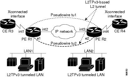
Figure 23 shows how the L2TPv3 feature is used to set up VPNs using Layer 2 tunneling over an IP network. All traffic between two customer network sites is encapsulated in IP packets carrying L2TP data messages and sent across an IP network. The backbone routers of the IP network treat the traffic as any other IP traffic and does not need to know anything about the customer networks.
Both PE routers R1 and R2 provide L2TPv3 services. The R1 and R2 routers communicate with each other using a pseudowire over the IP backbone network through a path comprising the interfaces int1 and int2, the IP network, and interfaces int3 and int4. The CE routers R3 and R4 communicate through a pair of cross-connected Ethernet or 802.1q VLAN interfaces using an L2TPv3 session. The L2TPv3 session tu1 is a pseudowire configured between interface int1 on R1 and interface int4 on R2. Any packet arriving on interface int1 on R1 is encapsulated and sent through the pseudowire (tu1) to R2. R2 decapsulates the packet and sends it on interface int4 to R4. When R4 needs to send a packet to R3, the packet follows the same path in reverse.
Figure 23 L2TPv3 Operation
L2TPv3 Benefits
L2TPv3 provides the following benefits:
•
•
•
L2TPv3 Features
L2TPv3 provides cross-connect support for Ethernet, 802.1q (VLAN), and Frame Relay, using the sessions described in the following sections:
L2TPv3 also supports:
•
•
•
•
•
•
•
•
•
Static L2TPv3 Sessions
Typically, the L2TP control plane is responsible for negotiating session parameters (such as the session ID or the cookie) to set up the session; however, some IP networks require sessions to be configured so that no signaling is required for session establishment. Therefore, you can set up static L2TPv3 sessions for a PE router by configuring fixed values for the fields in the L2TP data header. A static L2TPv3 session allows the PE to tunnel L2 traffic as soon as the AC to which the session is bound comes up.
Note
When you use a static L2TPv3 session, you cannot perform circuit interworking (for example, LMI) because there is no facility to exchange control messages. To perform circuit interworking, you must use a dynamic session.
Dynamic L2TPv3 Sessions
A dynamic L2TP session is established through the exchange of control messages containing attribute-value pair (AVP). Each AVP contains information about the nature of the L2 link being forwarded: including the payload type, virtual circuit (VC) ID, and so on.
Multiple L2TP sessions can exist between a pair of PEs, and can be maintained by a single control-channel. Session IDs and cookies are dynamically generated and exchanged as part of a dynamic session setup. Sequencing configuration is also exchanged and circuit state changes are conveyed using the set link info (SLI) message.
Sequencing
Although the correct sequence of received L2 frames is guaranteed by some L2 technologies (by the nature of the link, such as a serial line) or the protocol itself, forwarded L2 frames may be lost, duplicated, or reordered when they traverse a network as IP packets. If the L2 protocol does not provide an explicit sequencing mechanism, you can configure L2TP to sequence its data packets according to the data channel sequencing mechanism described in the L2TPv3 IETF l2tpext working group draft.
A receiver of L2TP data packets mandates sequencing through the sequencing required AVP when the session is being negotiated. A sender that receives this AVP (or that is manually configured to send sequenced packets) uses the L2-specific pseudowire control encapsulation defined in L2TPv3.
Currently, you can configure L2TP only to drop out-of-order packets; you cannot configure L2TP to deliver the packets out-of-order. No reordering mechanism is available.
Local Switching
An AC to AC cross-connect, also called local switching, is a building block of L2VPN that allows frames to switch between two different ACs on the same PE (see Figure 24). Local switching is supported for both static and dynamic sessions.
You must configure separate IP addresses for each cross-connect statement.
Note
The following configurations are supported for local switching:
•
•
•
•
Note
Figure 24 Local Switching Operation

Local Switching: Quality of Service
The following quality of service (QoS) requirements apply to local switching:
•
•
•
•
•
•
L2TPv3 Pseudowire Manager
The pseudowire manager is a client library provided by the pseudowire signaling module that runs in the context of the L2VPN process. This client library implements interface to pseudo-wire signaling protocol for specific pseudowire type.
L2TPv3 Type of Service Marking
When L2 traffic is tunneled across an IP network, information contained in the type of service (ToS) bits may be transferred to the L2TP-encapsulated IP packets in one of the following ways:
•
•
Keepalive
The keepalive mechanism for L2TPv3 extends only to the endpoints of the tunneling protocol. L2TP has a reliable control message delivery mechanism that serves as the basis for the keepalive mechanism. The keepalive mechanism consists of an exchange of L2TP hello messages.
If a keepalive mechanism is required, the control plane is used, although it may not be used to bring up sessions. You can manually configure sessions.
In the case of static L2TPv3 sessions, a control channel between the two L2TP peers is negotiated through the exchange of start control channel request (SCCRQ), start control channel replay (SCCRP), and start control channel connected (SCCCN) control messages. The control channel is responsible only for maintaining the keepalive mechanism through the exchange of hello messages.
The interval between hello messages is configurable per control channel. If one peer detects that the other has gone down through the keepalive mechanism, it sends a StopCCN control message and then notifies all of the pseudowires to the peer about the event. This notification results in the teardown of both manually configured and dynamic sessions.
Maximum Transmission Unit Handling
It is important that you configure an maximum transmission unit (MTU) appropriate for each L2TPv3 tunneled link. The configured MTU size ensures the following:
•
•
L2TPv3 handles the MTU as follows:
•
How to Implement Layer 2 Tunnel Protocol Version 3
This section includes the tasks required to implement L2TPv3, as follows:
•
•
•
•
Configuring a Pseudowire Class
Perform this task to configure a pseudowire class or template.
SUMMARY STEPS
1.
2.
3.
4.
5.
6.
7.
8.
or
commitDETAILED STEPS
Configuring L2TP Control-Channel Parameters
This section describes the tasks to create a template of L2TP control-channel parameters that can be inherited by different pseudowire classes. The three main parameters described are:
•
•
•
L2TP control-channel parameters are used in control-channel authentication, keepalive messages, and control-channel negotiation. In an L2TPv3 session, the same L2TP class must be specified in the pseudowire configured on the PE router at each end of the control-channel.
Note
•
The three main groups of L2TP control-channel parameters that you can configure in an L2TP class are described in the following subsections:
•
•
•
Note
Configuring L2TP Control-Channel Timing Parameters
The following L2TP control-channel timing parameters can be configured in L2TP class configuration mode:
•
•
•
Note
SUMMARY STEPS
1.
2.
3.
4.
5.
DETAILED STEPS
Configuring L2TPv3 Control-Channel Authentication Parameters
Two methods of control-channel message authentication are available:
•
•
You can enable both methods of authentication to ensure interoperability with peers that support only one of these methods of authentication, but this configuration will yield control of which authentication method is used to the peer PE router. Enabling both methods of authentication should be considered an interim solution to solve backward-compatibility issues during software upgrades.
The principal difference between the L2TPv3 Control Message Hashing feature and CHAP-style L2TP control-channel authentication is that, instead of computing the hash over selected contents of a received control message, the L2TPv3 Control Message Hashing feature uses the entire message in the hash. In addition, instead of including the hash digest in only the SCCRP and SCCCN messages, it includes it in all messages.
This section also describes how to configure L2TPv3 digest secret graceful switchover (see Configuring L2TPv3 Digest Secret Graceful Switchover,) which lets you make the transition from an old L2TPv3 control-channel authentication password to a new L2TPv3 control-channel authentication password without disrupting established L2TPv3 tunnels.
Note
Configuring Authentication for the L2TP Control-Channel
The L2TP control-channel method of authentication is the older, CHAP-like authentication system inherited from L2TPv2.
The following L2TP control-channel authentication parameters can be configured in L2TP class configuration mode:
•
•
•
This task configures a set of authentication control-channel parameters in an L2TP class. All of the authentication control-channel parameter configurations may be configured in any order. If these parameters are not configured, the default values are applied.
SUMMARY STEPS
1.
2.
3.
4.
5.
DETAILED STEPS
Configuring L2TPv3 Control Message Hashing
Perform this task to configure L2TPv3 Control Message Hashing feature for an L2TP class.
L2TPv3 control message hashing incorporates authentication or integrity check for all control messages. This per-message authentication is designed to guard against control message spoofing and replay attacks that would otherwise be trivial to mount against the network.
Enabling the L2TPv3Control Message Hashing feature will impact performance during control-channel and session establishment because additional digest calculation of the full message content is required for each sent and received control message. This is an expected trade-off for the additional security afforded by this feature. In addition, network congestion may occur if the receive window size is too small. If the L2TPv3 Control Message Hashing feature is enabled, message digest validation must be enabled. Message digest validation deactivates the data path received sequence number update and restricts the minimum local receive window size to 35.
You can configure control-channel authentication or control message integrity checking; however, control-channel authentication requires participation by both peers, and a shared secret must be configured on both routers. Control message integrity check is unidirectional, and requires configuration on only one of the peers.
SUMMARY STEPS
1.
2.
3.
4.
DETAILED STEPS
Configuring L2TPv3 Digest Secret Graceful Switchover
Perform this task to make the transition from an old L2TPv3 control-channel authentication password to a new L2TPv3 control-channel authentication password without disrupting established L2TPv3 tunnels.
Note
L2TPv3 control-channel authentication occurs using a password that is configured on all participating peer PE routers. The L2TPv3 Digest Secret Graceful Switchover feature allows a transition from an old control-channel authentication password to a new control-channel authentication password without disrupting established L2TPv3 tunnels.
Before performing this task, you must enable control-channel authentication (see Configuring L2TPv3 Control Message Hashing).
Note
SUMMARY STEPS
1.
2.
3.
4.
or
commit5.
6.
7.
8.
9.
or
commit10.
DETAILED STEPS
Configuring L2TP Control-Channel Maintenance Parameters
Perform this task to configure the interval used for hello messages in an L2TP class.
SUMMARY STEPS
1.
2.
3.
DETAILED STEPS
Configuring L2TPv3 Pseudowires
Perform the following tasks to configure static and dynamic L2TPv3 pseudowires:
•
•
Configuring a Dynamic L2TPv3 Pseudowire
Perform this task to configure a dynamic L2TPv3 pseudowire.
SUMMARY STEPS
1.
2.
3.
4.
5.
6.
7.
or
commit8.
9.
10.
11.
or
commitDETAILED STEPS
Configuring a Static L2TPv3 Pseudowire
Perform this task to configure a static L2TPv3 pseudowire.
SUMMARY STEPS
1.
2.
3.
4.
5.
6.
7.
8.
9.
10.
11.
or
commit12.
13.
14.
15.
or
commitDETAILED STEPS
Configuring the Cross-connect Attachment Circuit
This configuration procedure binds an Ethernet 802.1q VLAN, or Frame Relay AC to an L2TPv3 pseudowire for cross-connect service. The virtual circuit identifier that you configure creates the binding between a pseudowire configured on a PE router and an AC in a CE device. The virtual circuit identifier configured on the PE router at one end of the L2TPv3 control-channel must also be configured on the peer PE router at the other end.
SUMMARY STEPS
1.
2.
3.
4.
5.
6.
7.
8.
or
commit9.
10.
11.
12.
or
commitDETAILED STEPS
Configuration Examples for Layer 2 Tunnel Protocol Version 3
This section provides the following configuration examples:
•
•
•
•
•
Configuring an L2TP Class for L2TPv3-based L2VPN PE Routers: Example
The following example shows how to configure a L2TP class with L2TPv3 based L2VPN for a PE router.
configurel2tp-class l2tptestreceive-window 256retransmit retries 8retransmit initial retries 10retransmit initial timeout max 4retransmit initial timeout min 2timeout setup 90hostname PE1hello-interval 100digest secret cisco hash MD5endConfiguring a Pseudowire Class: Example
The following example shows a pseudowire class configuration on a PE router:
configurel2vpnpw-class FR1encapsulation l2tpv3protocol l2tpv3 class FR-l2tptos value 100 reflectttl 50ipv4 source 127.0.0.1cookie size 4sequencing both resync 150Configuring L2TPv3 Control Channel Parameters: Example
The following example shows a typical L2TPv3 control-channel configuration:
configurel2tp-class FR-l2tpauthenticationhostname R2-PE1password 7 121A0C041104hello-interval 10digest secret 7 02050D480809Configuring the Cross-Connect Group: Example
The following example shows how to group all cross -connects for FR1:
configurel2vpnxconnect group FR1p2p FR1interface Serial0/3/3/0/3/1:0.101neighbor 10.1.1.1 pw-id 2001pw-class FR1Configuring an Interface for Layer 2 Transport Mode: Example
The following example shows how to configure an interface to operate in Layer 2 transport mode:
configureinterface Serial0/3/3/0/3/1:0encapsulation frame-relayframe-relay lmi-type ansiexitinterface Serial0/3/3/0/3/1:0.101 l2transportpvc 101Additional References
The following sections provide additional information related to L2TPv3.
Related Documents
Standards
MIBs
—
To locate and download MIBs using Cisco IOS XR software, use the Cisco MIB Locator found at the following URL and choose a platform under the Cisco Access Products menu: http://cisco.com/public/sw-center/netmgmt/cmtk/mibs.shtml
RFCs
Technical Assistance
 Feedback
Contact Cisco
- Open a Support Case

- (Requires a Cisco Service Contract)
This Document Applies to These Products
- Collaboration Endpoints - Retired Products
- Conferencing - Retired Products
- Contact Center - Retired Products
- Optical Networking - Retired Products
- Routers - Retired Products
- Security - Retired Products
- Servers - Unified Computing (UCS) Retired Products
- Storage Networking Retired Products
- Switches - Retired Products
- Video - Retired Products
- Wireless - Retired Products