Implementing RSVP for MPLS-TE and MPLS O-UNI on Cisco IOS XR Software
Available Languages
Table Of Contents
Implementing RSVP for MPLS-TE and MPLS O-UNI on Cisco IOS XR Software
Prerequisites for Implementing RSVP for MPLS-TE and MPLS O-UNI
Information About Implementing RSVP for MPLS-TE and MPLS O-UNI
Overview of RSVP for MPLS-TE and MPLS O-UNI
Graceful Restart: Standard and Interface-Based
Information About Implementing RSVP Authentication
Global, Interface, and Neighbor Authentication Modes
Guidelines for Window-Size and Out-of-Sequence Messages
Configuring Traffic Engineering Tunnel Bandwidth
Confirming DiffServ-TE Bandwidth
Configuring MPLS O-UNI Bandwidth
Configuring ACL-based Prefix Filtering
Configuring ACLs for Prefix Filtering
Configuring RSVP Packet Dropping
How to Implement RSVP Authentication
Configuring Global Configuration Mode RSVP Authentication
Enabling RSVP Authentication Using the Keychain in Global Configuration Mode
Configuring a Lifetime for RSVP Authentication in Global Configuration Mode
Configuring the Window Size for RSVP Authentication in Global Configuration Mode
Configuring an Interface for RSVP Authentication
Specifying the RSVP Authentication Keychain in Interface Mode
Configuring a Lifetime for an Interface for RSVP Authentication
Configuring the Window Size for an Interface for RSVP Authentication
Configuring RSVP Neighbor Authentication
Specifying the Keychain for RSVP Neighbor Authentication
Configuring a Lifetime for RSVP Neighbor Authentication
Configuring the Window Size for RSVP Neighbor Authentication
Verifying the Details of the RSVP Authentication
Eliminating Security Associations for RSVP Authentication
Configuration Examples for RSVP
Bandwidth Configuration (Prestandard): Example
Bandwidth Configuration (MAM): Example
Bandwidth Configuration (RDM): Example
Refresh Reduction and Reliable Messaging Configuration: Example
Changing the Refresh Interval and the Number of Refresh Messages
Configuring Retransmit Time Used in Reliable Messaging
Configuring Acknowledgement Times
Changing the Summary Refresh Message Size
Configuring Graceful Restart: Example
Enabling Interface-Based Graceful Restart
Configuring ACL-based Prefix Filtering: Example
Setting DSCP for RSVP Packets: Example
Configuration Examples for RSVP Authentication
RSVP Authentication Global Configuration Mode: Example
RSVP Authentication for an Interface: Example
RSVP Neighbor Authentication: Example
RSVP Authentication by Using All the Modes: Example
Implementing RSVP for MPLS-TE and MPLS O-UNI on Cisco IOS XR Software
Multiprotocol Label Switching (MPLS) is a standards-based solution, driven by the Internet Engineering Task Force (IETF), devised to convert the Internet and IP backbones from best-effort networks into business-class transport media.
Resource Reservation Protocol (RSVP) is a signaling protocol that enables systems to request resource reservations from the network. RSVP processes protocol messages from other systems, processes resource requests from local clients, and generates protocol messages. As a result, resources are reserved for data flows on behalf of local and remote clients. RSVP creates, maintains, and deletes these resource reservations.
RSVP provides a secure method to control quality-of-service (QoS) access to a network.
MPLS Traffic Engineering (MPLS-TE) and MPLS Optical User Network Interface (MPLS O-UNI) use RSVP to signal label switched paths (LSPs).
Feature History for Implementing RSVP for MPLS-TE and MPLS O-UNI on Cisco IOS XR Software
Contents
•
Prerequisites for Implementing RSVP for MPLS-TE and MPLS O-UNI
•
•
•
•
•
Prerequisites for Implementing RSVP for MPLS-TE and MPLS O-UNI
The following are prerequisites are required to implement RSVP for MPLS-TE and MPLS O-UNI:
•
•
Information About Implementing RSVP for MPLS-TE and MPLS O-UNI
To implement MPLS RSVP, you must understand the following concepts, which are described in the sections that follow:
•
For information on how to implement RSVP authentication, see How to Implement RSVP Authentication.
Overview of RSVP for MPLS-TE and MPLS O-UNI
RSVP is a network control protocol that enables Internet applications to signal LSPs for MPLS-TE,
and LSPs for O-UNI. The RSVP implementation is compliant with the IETF RFC 2205, RFC 3209, and OIF2000.125.7.When configuring an O-UNI LSP, the RSVP session is bidirectional. The exchange of data between a pair of machines actually constitutes a single RSVP session. The RSVP session is established using an Out-Of-Band (OOB) IP Control Channel (IPCC) with the neighbor. The RSVP messages are transported over an interface other than the data interface.
RSVP supports extensions according to OIF2000.125.7 requirements, including:
•
•
•
•
RSVP is automatically enabled on interfaces on which MPLS-TE is configured. For MPLS-TE LSPs with non-zero bandwidth, the RSVP bandwidth has to be configured on the interfaces. There is no need to configure RSVP, if all MPLS-TE LSPs have zero bandwidth. For O-UNI, there is no need for any RSVP configuration.
RSVP Refresh Reduction, defined in RFC2961, includes support for reliable messages and summary refresh messages. Reliable messages are retransmitted rapidly if the message is lost. Because each summary refresh message contains information to refresh multiple states, this greatly reduces the amount of messaging needed to refresh states. For refresh reduction to be used between two routers, it must be enabled on both routers. Refresh Reduction is enabled by default.
Message rate limiting for RSVP allows you to set a maximum threshold on the rate at which RSVP messages are sent on an interface. Message rate limiting is disabled by default.
The process that implements RSVP is restartable. A software upgrade, process placement or process failure of RSVP or any of its collaborators, has been designed to ensure Nonstop Forwarding (NSF) of the data plane.
RSVP supports graceful restart, which is compliant with RFC 3473. It follows the procedures that apply when the node reestablishes communication with the neighbor's control plane within a configured restart time.
It is important to note that RSVP is not a routing protocol. RSVP works in conjunction with routing protocols and installs the equivalent of dynamic access lists along the routes that routing protocols calculate. Because of this, implementing RSVP in an existing network does not require migration to a new routing protocol.
LSP Setup
LSP setup is initiated when the LSP head node sends path messages to the tail node (see Figure 7).
Figure 7 RSVP Operation
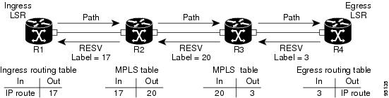
The Path messages reserve resources along the path to each node, creating Path soft states on each node. When the tail node receives a path message, it sends a reservation (RESV) message with a label back to the previous node. When the reservation message arrives at the previous node, it causes the reserved resources to be locked and forwarding entries are programmed with the MPLS label sent from the tail-end node. A new MPLS label is allocated and sent to the next node upstream.
When the reservation message reaches the head node, the label is programmed and the MPLS data starts to flow along the path.
Figure 7 illustrates an LSP setup for non-O-UNI applications. In the case of an O-UNI application, the RSVP signaling messages are exchanged on a control channel, and the corresponding data channel to be used is acquired from the LMP Manager module based on the control channel. Also the O-UNI LSP's are by default bidirectional while the MPLS-TE LSP's are uni-directional.
High Availability
RSVP has been designed to ensure nonstop forwarding under the following constraints:
•
•
•
The RSVP high availability (HA) design follows the constraints of the underlying architecture where processes can fail without affecting the operation of other processes. A process failure of RSVP or any of its collaborators does not cause any traffic loss or cause established LSPs to go down. When RSVP restarts, it recovers its signaling states from its neighbors. No special configuration or manual intervention are required. You may configure RSVP graceful restart, which offers a standard mechanism to recover RSVP state information from neighbors after a failure.
Graceful Restart
RSVP graceful restart provides a control plane mechanism to ensure high availability, which allows detection and recovery from failure conditions while preserving nonstop forwarding services on the systems running Cisco IOS XR software.
RSVP graceful restart provides a mechanism that minimizes the negative effects on MPLS traffic caused by the following types of faults:
•
•
The procedure for RSVP graceful restart is described in the "Fault Handling" section of RFC 3473: Generalized MPLS Signaling, RSVP-TE Extensions. One of the main advantages of using RSVP graceful restart is recovery of the control plane while preserving nonstop forwarding and existing labels.
Graceful Restart: Standard and Interface-Based
When you configure RSVP graceful restart, Cisco IOS XR software sends and expects node-id address based Hello messages (that is, Hello Request and Hello Ack messages). The RSVP graceful restart Hello session is not established if the neighbor router does not respond with a node-id based Hello Ack message.
You can also configure graceful restart to respond (send Hello Ack messages) to interface-address based Hello messages sent from a neighbor router in order to establish a graceful restart Hello session on the neighbor router. If the neighbor router does not respond with node-id based Hello Ack message, however, the RSVP graceful restart Hello session is not established.
Cisco IOS XR software provides two commands to configure graceful restart:
•
•

Note
For detailed configuration steps, refer to Enabling Graceful Restart.
Graceful Restart: Figure
Figure 8 illustrates how RSVP graceful restart handles a node failure condition.
Figure 8 Node Failure with RSVP
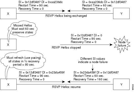
RSVP graceful restart requires the use of RSVP hello messages. Hello messages are used between RSVP neighbors. Each neighbor can autonomously issue a hello message containing a hello request object. A receiver that supports the hello extension replies with a hello message containing a hello acknowledgement (ACK) object. This means that a hello message contains either a hello Request or a hello ACK object. These two objects have the same format.
The restart cap object indicates a node's restart capabilities. It is carried in hello messages if the sending node supports state recovery. The restart cap object has the following two fields:
•
•
For graceful restart, the hello messages are sent with an IP Time to Live (TTL) of 64. This is because the destination of the hello messages can be multiple hops away. If graceful restart is enabled, hello messages (containing the restart cap object) are send to an RSVP neighbor when RSVP states are shared with that neighbor.
Restart cap objects are sent to an RSVP neighbor when RSVP states are shared with that neighbor. If the neighbor replies with hello messages containing the restart cap object, the neighbor is considered to be graceful restart capable. If the neighbor does not reply with hello messages or replies with hello messages that do not contain the restart cap object, RSVP backs off sending hellos to that neighbor. If graceful restart is disabled, no hello messages (Requests or ACKs) are sent. If a hello Request message is received from an unknown neighbor, no hello ACK is sent back.
ACL-based Prefix Filtering
RSVP provides for the configuration of extended access lists (ACLs) to forward, drop, or perform normal processing on RSVP Router-Alert (RA) packets. Prefix filtering is designed for use at core access routers in order that RA packets (identified by a source/destination address) can be seamlessly forwarded across the core from one access point to another (or, conversely to be dropped at this node). RSVP applies prefix filtering rules only to RA packets because RA packets contain source and destination addresses of the RSVP flow.
Note
For each incoming RSVP RA packet, RSVP inspects the IP header and attempts to match the source/destination IP addresses with a prefix configured in an extended ACL. The results are as follows:
•
•
•
If there is no explicit permit or explicit deny, the ACL infrastructure returns an implicit (default) deny. RSVP may be configured to drop the packet. By default, RSVP processes the packet if the ACL match yields an implicit (default) deny.
Information About Implementing RSVP Authentication
Before implementing RSVP authentication, you must configure a keychain first. The name of the keychain must be the same as the one used in the keychain configuration. For more information about configuring keychains, see Cisco IOS XR System Security Configuration Guide.
Note
To implement RSVP authentication on Cisco IOS XR software, you must understand the following concepts:
•
•
•
RSVP Authentication Functions
You can carry out the following tasks with RSVP authentication:
•
•
•
•
•
RSVP Authentication Design
Network administrators need the ability to establish a security domain to control the set of systems that initiates RSVP requests.
The RSVP authentication feature permits neighbors in an RSVP network to use a secure hash to sign all RSVP signaling messages digitally, thus allowing the receiver of an RSVP message to verify the sender of the message without relying solely on the sender's IP address.
The signature is accomplished on a per-RSVP-hop basis with an RSVP integrity object in the RSVP message as defined in RFC 2747. This method provides protection against forgery or message modification. However, the receiver must know the security key used by the sender to validate the digital signature in the received RSVP message.
Network administrators manually configure a common key for each RSVP neighbor on the shared network.
The following reasons explain how to choose between global, interface, or neighbor configuration modes:
•
•
Global configuration mode configures the defaults for interface and neighbor interface modes. These modes, unless explicitly configured, inherit the parameters from global configuration mode, as follows:
•
•
•
Global, Interface, and Neighbor Authentication Modes
You can configure global defaults for all authentication parameters including key, window size, and lifetime. These defaults are inherited when you configure authentication for each neighbor or interface. However, you can also configure these parameters individually on a neighbor or interface basis, in which case the global values (configured or default) are no longer inherited.
Note
Global keys simplify the configuration and eliminate the chances of a key mismatch when receiving messages from multiple neighbors and multiple interfaces. However, global keys do not provide the best security.
Interface keys are used to secure specific interfaces between two RSVP neighbors. Because many of the RSVP messages are IP routed, there are many scenarios in which using interface keys are not recommended. If all keys on the interfaces are not the same, there is a risk of a key mismatch for the following reasons:
•
•
•
Neighbor-based keys are particularly useful in a network in which some neighbors support RSVP authentication procedures and others do not. When the neighbor-based keys are configured for a particular neighbor, you are advised to configure all the neighbor's addresses and router IDs for RSVP authentication.
Security Association
A security association (SA) is defined as a collection of information that is required to maintain secure communications with a peer to counter replay attacks, spoofing, and packet corruption.
Table 2 lists the main parameters that define a security association.
An SA is created dynamically when sending and receiving messages that require authentication. The neighbor, source, and destination addresses are obtained either from the IP header or from an RSVP object, such as a HOP object, and whether the message is incoming or outgoing.
When the SA is created, an expiration timer is created. When the SA authenticates a message, it is marked as recently used. The lifetime timer periodically checks if the SA is being used. If so, the flag is cleared and is cleaned up for the next period unless it is marked again.
Table 3 shows how to locate the source and destination address keys for an SA that is based on the message type.
Key-source Key-chain
The key-source key-chain is used to specify which keys to use.
You configure a list of keys with specific IDs and have different lifetimes so that keys are changed at predetermined intervals automatically, without any disruption of service. Rollover enhances network security by minimizing the problems that could result if an untrusted source obtained, deduced, or guessed the current key.
RSVP handles rollover by using the following key ID types:
•
•
For more information about implementing keychain management on Cisco IOS XR Software, see Cisco IOS XR System Security Configuration Guide.
Guidelines for Window-Size and Out-of-Sequence Messages
The following guidelines are required for window-size and out-of-sequence messages:
•
•
•
Caveats for Out-of-Sequence
The following caveats are listed for out-of-sequence:
•
•
•
•
Because all out-of-sequence messages are dropped, the sender must retransmit them. Because RSVP state timeouts are generally long, out-of-sequence messages during a transient state do not lead to a state timeout.
How to Implement RSVP
RSVP requires coordination among several routers, establishing exchange of RSVP messages to set up LSPs. Depending on the client application, RSVP requires some basic configuration, as described in the following sections:
•
•
•
•
Configuring Traffic Engineering Tunnel Bandwidth
To configure traffic engineering tunnel bandwidth, you must first set up TE tunnels and configure the reserved bandwidth per interface (there is no need to configure bandwidth for the data channel or the control channel).
Cisco IOS XR software supports two DS-TE modes: Prestandard and IETF.
The configuration steps for each option are described in the following sections in Implementing MPLS Traffic Engineering on Cisco IOS XR Software:
•
•
•
Note
Note
Confirming DiffServ-TE Bandwidth
Perform this task to confirm DiffServ-TE bandwidth.
In RSVP global and subpools, reservable bandwidths are configured per interface to accommodate TE tunnels on the node. Available bandwidth from all configured bandwidth pools is advertised using IGP. RSVP is used to signal the TE tunnel with appropriate bandwidth pool requirements.
SUMMARY STEPS
1.
2.
3.
4.
5.
or
commitDETAILED STEPS
Configuring MPLS O-UNI Bandwidth
For this application you do not need to configure bandwidth for the data channel or the control channel. There is no other specific RSVP configuration needed for this application.
Enabling Graceful Restart
Perform this task to enable graceful restart for implementations using both node-id- and interface-based hellos.
RSVP graceful restart provides a control plane mechanism to ensure high availability, which allows detection and recovery from failure conditions while preserving nonstop forwarding services.
SUMMARY STEPS
1.
2.
3.
4.
5.
or
commitDETAILED STEPS
Configuring ACL-based Prefix Filtering
This section includes two procedures associated with RSVP Prefix Filtering:
•
•
Configuring ACLs for Prefix Filtering
Perform this task to configure an extended access list ACL that identifies the source and destination prefixes used for packet filtering.
Note
SUMMARY STEPS
1.
2.
3.
4.
or
commitDETAILED STEPS
Configuring RSVP Packet Dropping
Perform this task to configure RSVP to drop RA packets when the ACL match returns an implicit (default) deny.
Note
SUMMARY STEPS
1.
2.
3.
4.
or
commitDETAILED STEPS
Verifying RSVP Configuration
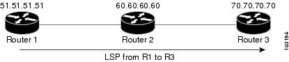
Figure 9 illustrates the topology that forms the basis for this section.
Figure 9 Sample Topology
To verify RSVP configuration, perform the following steps.
SUMMARY STEPS
1.
2.
3.
4.
5.
6.
7.
8.
DETAILED STEPS
Step 1
Use this command to verify that all routers on the path of the LSP are configured with at least one Path State Block (PSB) and one Reservation State Block (RSB) per session. For example:
RP/0/RP0/CPU0:router# show rsvp sessionType Destination Add DPort Proto/ExtTunID PSBs RSBs Reqs---- --------------- ----- --------------- ----- ----- -----LSP4 172.16.70.70 6 10.51.51.51 1 1 0In the example above, the output represents an LSP from ingress (head) router 10.51.51.51 to egress (tail) router 172.16.70.70. The tunnel ID (a.k.a destination port) is 6.
•
•
Go to the downstream router R2 and display the session information:
•
•
•
Step 2
Use this command to verify whether RSVP message are being transmitted and received. For example:
RP/0/RP0/CPU0:router# show rsvp counters messages summaryAll RSVP Interfaces Recv Xmit Recv XmitPath 0 25 Resv 30 0PathError 0 0 ResvError 0 1PathTear 0 30 ResvTear 12 0ResvConfirm 0 0 Ack 24 37Bundle 0 Hello 0 5099SRefresh 8974 9012 OutOfOrder 0Retransmit 20 Rate Limited 0Step 3
Use this command to see how many RSVP states have expired. Since RSVP uses a soft-state mechanism, some failures will lead to RSVP states to expire due to lack of refresh from the neighbor. For example:
RP/0/RP0/CPU0:router# show rsvp counters eventsmgmtEthernet0/0/0/0 tunnel6Expired Path states 0 Expired Path states 0Expired Resv states 0 Expired Resv states 0NACKs received 0 NACKs received 0POS0/3/0/0 POS0/3/0/1Expired Path states 0 Expired Path states 0Expired Resv states 0 Expired Resv states 0NACKs received 0 NACKs received 0POS0/3/0/2 POS0/3/0/3Expired Path states 0 Expired Path states 0Expired Resv states 0 Expired Resv states 1NACKs received 0 NACKs received 1Step 4
Use this command to verify that refresh reduction is working on a particular interface. For example:
RP/0/RP0/CPU0:router# show rsvp interface pos0/3/0/3 detailINTERFACE: POS0/3/0/3 (ifh=0x4000D00).BW (bits/sec): Max=1000M. MaxFlow=1000M. Allocated=1K (0%). MaxSub=0.Signalling: No DSCP marking. No rate limiting.States in: 1. Max missed msgs: 4.Expiry timer: Running (every 30s). Refresh interval: 45s.Normal Refresh timer: Not running. Summary refresh timer: Running.Refresh reduction local: Enabled. Summary Refresh: Enabled (4096 bytes max).Reliable summary refresh: Disabled.Ack hold: 400 ms, Ack max size: 4096 bytes. Retransmit: 900ms.Neighbor information:Neighbor-IP Nbor-MsgIds States-out Refresh-Reduction Expiry(min::sec)-------------- -------------- ---------- ------------------ ----------------64.64.64.65 1 1 Enabled 14::45Step 5
Use this command to verify that graceful restart is enabled locally. For example:
RP/0/RP0/CPU0:router# show rsvp graceful-restartGraceful restart: enabled Number of global neighbors: 1Local MPLS router id: 10.51.51.51Restart time: 60 seconds Recovery time: 0 secondsRecovery timer: Not runningHello interval: 5000 milliseconds Maximum Hello miss-count: 3Step 6
Use this command to verify that graceful restart is enabled on the neighbor(s). In the following examples, the neighbor 192.168.60.60 is not responding to hello messages:
RP/0/RP0/CPU0:router# show rsvp graceful-restart neighborsNeighbor App State Recovery Reason Since LostCnt--------------- ----- ------ -------- ------------ -------------------- --------192.168.60.60 MPLS INIT DONE N/A 12/06/2003 19:01:49 0RP/0/RP0/CPU0:router# show rsvp graceful-restart neighbors detailNeighbor: 192.168.60.60 Source: 10.51.51.51 (MPLS)Hello instance for application MPLSHello State: INIT (for 3d23h)Number of times communications with neighbor lost: 0Reason: N/ARecovery State: DONENumber of Interface neighbors: 1address: 10.64.64.65Restart time: 0 seconds Recovery time: 0 secondsRestart timer: Not runningRecovery timer: Not runningHello interval: 5000 milliseconds Maximum allowed missed Hello messages: 3Step 7
Use this command to verify available RSVP bandwidth. For example:
RP/0/RP0/CPU0:router# show rsvp interfaceInterface MaxBW MaxFlow Allocated MaxSub----------- -------- -------- --------------- --------Et0/0/0/0 0 0 0 ( 0%) 0PO0/3/0/0 1000M 1000M 0 ( 0%) 0PO0/3/0/1 1000M 1000M 0 ( 0%) 0PO0/3/0/2 1000M 1000M 0 ( 0%) 0PO0/3/0/3 1000M 1000M 1K ( 0%) 0Step 8
Use this command to verify RSVP neighbors. For example:
RP/0/RP0/CPU0:router# show rsvp neighbor detailGlobal Neighbor: 40.40.40.40Interface Neighbor: 1.1.1.1Interface: POS0/0/0/0Refresh Reduction: "Enabled" or "Disabled".Remote epoch: 0xXXXXXXXXOut of order messages: 0Retransmitted messages: 0Interface Neighbor: 2.2.2.2Interface: POS0/1/0/0Refresh Reduction: "Enabled" or "Disabled".Remote epoch: 0xXXXXXXXXOut of order messages: 0Retransmitted messages: 0
How to Implement RSVP Authentication
There are three types of RSVP authentication modes—global, interface, and neighbor. The sections that follow describe how to implement RSVP authentication for each mode:
•
•
•
•
•
Configuring Global Configuration Mode RSVP Authentication
This section includes the following procedures for RSVP authentication in global configuration mode, as follows:
•
•
•
Enabling RSVP Authentication Using the Keychain in Global Configuration Mode
Perform this task to enable RSVP authentication for cryptographic authentication by specifying the keychain in global configuration mode.
Note
SUMMARY STEPS
1.
2.
3.
4.
or
commitDETAILED STEPS
Configuring a Lifetime for RSVP Authentication in Global Configuration Mode
Perform this task to configure a lifetime value for RSVP authentication in global configuration mode.
SUMMARY STEPS
1.
2.
3.
4.
or
commitDETAILED STEPS
Configuring the Window Size for RSVP Authentication in Global Configuration Mode
Perform this task to configure the window size for RSVP authentication in global configuration mode.
SUMMARY STEPS
1.
2.
3.
4.
or
commitDETAILED STEPS
Configuring an Interface for RSVP Authentication
This section contains the following procedures for configuring an interface for RSVP authentication:
•
•
•
Specifying the RSVP Authentication Keychain in Interface Mode
Perform this task to specify RSVP authentication keychain in interface mode.
You must configure a keychain first (see Cisco IOS XR System Security Configuration Guide).
SUMMARY STEPS
1.
2.
3.
4.
5.
or
commitDETAILED STEPS
Configuring a Lifetime for an Interface for RSVP Authentication
Perform this task to configure a lifetime for the security association for an interface.
SUMMARY STEPS
1.
2.
3.
4.
5.
or
commitDETAILED STEPS
Configuring the Window Size for an Interface for RSVP Authentication
Perform this task to configure the window size for an interface for RSVP authentication to check the validity of the sequence number received.
SUMMARY STEPS
1.
2.
3.
4.
5.
or
commitDETAILED STEPS
Configuring RSVP Neighbor Authentication
This section contains the following procedures for RSVP neighbor authentication:
•
•
•
Specifying the Keychain for RSVP Neighbor Authentication
Perform this task to specify the keychain RSVP neighbor authentication.
You must configure a keychain first (see Cisco IOS XR System Security Configuration Guide).
SUMMARY STEPS
1.
2.
3.
4.
or
commitDETAILED STEPS
Configuring a Lifetime for RSVP Neighbor Authentication
Perform this task to configure a lifetime for security association for RSVP neighbor authentication mode.
SUMMARY STEPS
1.
2.
3.
4.
or
commitDETAILED STEPS
Configuring the Window Size for RSVP Neighbor Authentication
Perform this task to configure the RSVP neighbor authentication window size to check the validity of the sequence number received.
SUMMARY STEPS
1.
2.
3.
4.
or
commitDETAILED STEPS
Verifying the Details of the RSVP Authentication
To display the security associations that RSVP has established with other RSVP neighbors, use the show rsvp authentication command.
Eliminating Security Associations for RSVP Authentication
To eliminate RSVP authentication SA's, use the clear rsvp authentication command. To eliminate RSVP counters for each SA, use the clear rsvp counters authentication command.
Configuration Examples for RSVP
The following section gives sample RSVP configurations for some of the supported RSVP features. More details on the commands can be found in the Resource Reservation Protocol Infrastructure Commands guide. Examples are provided for the following features:
•
•
•
•
•
•
•
Bandwidth Configuration (Prestandard): Example
The following example shows the configuration of bandwidth on an interface using prestandard DS-TE mode. The example configures an interface for a reservable bandwidth of 7500, specifies the maximum bandwidth for one flow to be 1000 and adds a sub-pool bandwidth of 2000:
rsvp interface pos 0/3/0/0bandwidth 7500 1000 sub-pool 2000Bandwidth Configuration (MAM): Example
The following example shows the configuration of bandwidth on an interface using MAM. The example shows how to limit the total of all RSVP reservations on POS interface 0/3/0/0 to 7500 kbps, and allows each single flow to reserve no more than 1000 kbps:
rsvp interface pos 0/3/0/0bandwidth mam 7500 1000Bandwidth Configuration (RDM): Example
The following example shows the configuration of bandwidth on an interface using RDM. The example shows how to limit the total of all RSVP reservations on PoS interface 0/3/0/0 to 7500 kbps, and allows each single flow to reserve no more than 1000 kbps:
rsvp interface pos 0/3/0/0bandwidth rdm 7500 1000Refresh Reduction and Reliable Messaging Configuration: Example
Refresh reduction feature as defined by RFC 2961 is supported and enabled by default. The following examples illustrate the configuration for the refresh reduction feature. Refresh reduction is used with a neighbor only if the neighbor supports it also.
Changing the Refresh Interval and the Number of Refresh Messages
The following example shows how to configure the refresh interval to 30 seconds on POS 0/3/0/0 and how to change the number of refresh messages the node can miss before cleaning up the state from the default value of 4 to 6:
rsvp interface pos 0/3/0/0signalling refresh interval 30signalling refresh missed 6Configuring Retransmit Time Used in Reliable Messaging
The following example shows how to set the retransmit timer to 2 seconds. To prevent unnecessary retransmits, the retransmit time value configured on the interface must be greater than the ACK hold time on its peer.
rsvp interface pos 0/4/0/1signalling refresh reduction reliable retransmit-time 2000Configuring Acknowledgement Times
The following example shows how to change the acknowledge hold time from the default value of 400 ms, to delay or speed up sending of ACKs, and the maximum acknowledgment message size from default size of 4096 bytes.
rsvp interface pos 0/4/0/1signalling refresh reduction reliable ack-hold-time 1000rsvp interface pos 0/4/0/1signalling refresh reduction reliable ack-max-size 1000
Note
Changing the Summary Refresh Message Size
The following example shows how to set the summary refresh message maximum size to 1500 bytes:
rsvp interface pos 0/4/0/1signalling refresh reduction summary max-size 1500Disabling Refresh Reduction
If the peer node does not support refresh reduction or for any other reason you want to disable refresh reduction on an interface, use the following commands to disable refresh reduction on that interface:
rsvp interface pos 0/4/0/1signalling refresh reduction disableConfiguring Graceful Restart: Example
RSVP graceful restart is configured globally or per interface (as are refresh-related parameters). The following examples show how to enable graceful restart, set the restart time, and change the hello message interval.
Enabling Graceful Restart
RSVP graceful restart is enabled by default. If disabled, enable it with the following command:
rsvp signalling graceful-restartEnabling Interface-Based Graceful Restart
Configure the RSVP graceful restart feature on an interface using the following command:
signalling hello graceful-restart interface-basedChanging the Restart-Time
Configure the restart time that is advertised in hello messages sent to neighbor nodes:
rsvp signalling graceful-restart restart-time 200Changing the Hello Interval
Configure the interval at which RSVP graceful restart hello messages are sent per neighbor, and change the number of hellos missed before the neighbor is declared down:
rsvp signalling hello graceful-restart refresh interval 4000rsvp signalling hello graceful-restart refresh misses 4Configuring ACL-based Prefix Filtering: Example
In the following example, when RSVP receives a Router Alert (RA) packet from source address 1.1.1.1 and 1.1.1.1 is not a local address, the packet is forwarded with IP TTL decremented. Packets destined to 2.2.2.2 are dropped. All other RA packets are processed as normal RSVP packets.
show run ipv4 access-listipv4 access-list rsvpacl10 permit ip host 1.1.1.1 any20 deny ip any host 2.2.2.2!show run rsvprsvpsignalling prefix-filtering access-list rsvpacl!Setting DSCP for RSVP Packets: Example
The following configuration can be used to set the Differentiated Services Code Point (DSCP) field in the IP header of RSVP packets:
rsvp interface pos0/2/0/1signalling dscp 20Configuration Examples for RSVP Authentication
This section provides the following configuration examples:
•
•
•
•
RSVP Authentication Global Configuration Mode: Example
The following configuration is used to enable authentication of all RSVP messages and to increase the default lifetime of the SAs:
rsvpauthenticationkey-source key-chain default_keyslife-time 3600!!
Note
RSVP Authentication for an Interface: Example
The following configuration is used to enable authentication of all RSVP messages that are being sent or received on one interface only, and sets the window-size of the SA's:
rsvpinterface GigabitEthernet0/6/0/0authenticationwindow-size 64!!
Note
RSVP Neighbor Authentication: Example
The following configuration is used to enable authentication of all RSVP messages that being sent to and received from only a particular IP address:
rsvpneighbor 10.0.0.1authenticationkey-source key-chain nbr_keys!!!RSVP Authentication by Using All the Modes: Example
The following configuration shows how to perform the following functions:
•
•
•
rsvpinterface GigabitEthernet0/6/0/0authenticationwindow-size 64!!neighbor 10.0.0.1authenticationkey-source key-chain nbr_keys!!authenticationkey-source key-chain default_keyslife-time 3600!!
Note
Additional References
The following section provides references related to implementing MPLS RSVP:
Related Documents
Standards
OIF2000.125.7
User Network Interface (UNI) 1.0 Signaling Specification
1 Not all supported standards are listed.
MIBs
—
To locate and download MIBs using Cisco IOS XR software, use the Cisco MIB Locator found at the following URL and choose a platform under the Cisco Access Products menu: http://cisco.com/public/sw-center/netmgmt/cmtk/mibs.shtml
RFCs
RFC 2205
Resource Reservation Protocol Version 1 Functional Specification
RFC 2747
RSVP Cryptographic Authentication
RFC 3209
RSVP-TE: Extensions to RSVP for LSP Tunnels
RFC 2961
RSVP Refresh Overhead Reduction Extensions
RFC 3473
Generalized MPLS Signaling, RSVP-TE Extensions
RFC 4090
Fast Reroute Extensions to RSVP-TE for LSP Tunnels
1 Not all supported RFCs are listed.
Technical Assistance
 Feedback
Contact Cisco
- Open a Support Case

- (Requires a Cisco Service Contract)
This Document Applies to These Products
- Collaboration Endpoints - Retired Products
- Conferencing - Retired Products
- Contact Center - Retired Products
- Optical Networking - Retired Products
- Routers - Retired Products
- Security - Retired Products
- Servers - Unified Computing (UCS) Retired Products
- Storage Networking Retired Products
- Switches - Retired Products
- Video - Retired Products
- Wireless - Retired Products