Marking Network Traffic
Available Languages
Table Of Contents
Prerequisites for Marking Network Traffic
Restrictions for Marking Network Traffic
Information About Marking Network Traffic
Purpose of Marking Network Traffic
Benefits of Marking Network Traffic
Two Methods for Marking Traffic Attributes
Method One: Using a set Command
Traffic Marking Procedure Flowchart
MQC and Network Traffic Marking
Traffic Classification Compared with Traffic Marking
Creating a Class Map for Marking Network Traffic
Creating a Table Map for Marking Network Traffic
Creating a Policy Map for Applying a QoS Feature to Network Traffic
Attaching the Policy Map to an Interface
Configuring QoS When Using IPSec VPNs
Configuration Examples for Marking Network Traffic
Creating a Class Map for Marking Network Traffic: Example
Creating a Table Map for Marking Network Traffic: Example
Creating a Policy Map for Applying a QoS Feature to Network Traffic: Examples
Attaching the Policy Map to an Interface: Example
Configuring QoS When Using IPSec VPNs: Example
Feature Information for Marking Network Traffic
Marking Network Traffic
Marking network traffic allows you to set or modify the attributes for traffic (that is, packets) belonging to a specific class or category. When used in conjunction with network traffic classification, marking network traffic is the foundation for enabling many quality of service (QoS) features on your network. This module contains conceptual information and the configuration tasks for marking network traffic.
Module History
This module was first published on May 2, 2005, and last updated on May 2, 2005.
Finding Feature Information in This Module
Your Cisco IOS software release may not support all features. To find information about feature support and configuration, use the "Feature Information for Marking Network Traffic" section.
Contents
•
Prerequisites for Marking Network Traffic
•
•
•
•
Prerequisites for Marking Network Traffic
•
Restrictions for Marking Network Traffic
•
–
–
–
–
–
Information About Marking Network Traffic
To mark network traffic, you should understand the following concepts:
•
•
•
•
•
Purpose of Marking Network Traffic
Traffic marking is a method used to identify certain traffic types for unique handling, effectively partitioning network traffic into different categories.
After the network traffic is organized into classes by traffic classification, traffic marking allows you to mark (that is, set or change) a value (attribute) for the traffic belonging to a specific class. For instance, you may want to change the class of service (CoS) value from 2 to 1 in one class, or you may want to change the differentiated services code point (DSCP) value from 3 to 2 in another class. In this module, these values are referred to as attributes.
Attributes that can be set and modified include the following:
•
•
•
•
•
•
•
•
•
•
Benefits of Marking Network Traffic
Improved Network Performance
Traffic marking allows you to fine-tune the attributes for traffic on your network. This increased granularity helps single out traffic that requires special handling, and thus, helps to achieve optimal application performance.
Traffic marking allows you to determine how traffic will be treated, based on how the attributes for the network traffic are set. It allows you to segment network traffic into multiple priority levels or classes of service based on those attributes, as follows:
•
•
•
–
–
•
•
Two Methods for Marking Traffic Attributes
There are two methods for specifying and marking traffic attributes:
•
With this method you configure individual set commands for the traffic attribute you want to mark.
•
With this method you configure the traffic attributes you want to mark once in a table map and then the markings can be propagated throughout the network.
These methods are further described in the sections that follow.
Method One: Using a set Command
You specify the traffic attribute you want to change with a set command configured in a policy map. Table 1 lists the available set commands and the corresponding attribute. Table 1 also includes the network layer and the network protocol typically associated with the traffic attribute.
Table 1 set Commands and Corresponding Traffic Attribute, Network Layer, and Protocol
set atm-clp
CLP bit
Layer 2
ATM
set cos
Layer 2 CoS value of the outgoing traffic
Layer 2
ATM, Frame Relay
set discard-class
discard-class value
Layer 2
ATM, Frame Relay
set dscp
DSCP value in the ToS byte
Layer 3
IP
set fr-de
DE bit setting in the address field of a Frame Relay frame
Layer 2
Frame Relay
set ip tos (route-map)
ToS bits in the header of an IP packet
Layer 3
IP
set mpls experimental imposition
MPLS EXP field on all imposed label entries
Layer 3
MPLS
set mpls experimental topmost
MPLS EXP field value in the topmost label on either an input or an output interface
Layer 3
MPLS
set precedence
precedence value in the packet header
Layer 3
IP
set qos-group
QoS group ID
Layer 3
IP, MPLS
1 Cisco IOS set commands can vary by release. See the command documentation for the Cisco IOS release you are using for more information.
If you are using individual set commands, those set commands are specified in a policy map. The following is a sample of a policy map configured with one of the set commands listed in Table 3.
In this sample configuration, the set atm-clp command has been configured in the policy map (policy1) to mark the CLP attribute.
enableconfigure terminalpolicy-map policy1class class1set atm-clpendFor information on configuring a policy map, see the "Creating a Policy Map for Applying a QoS Feature to Network Traffic" section.
The final task is to attach the policy map to the interface. For information on attaching the policy map to the interface, see the "Attaching the Policy Map to an Interface" section.
Method Two: Using a Table Map
You can create a table map that can be used to mark traffic attributes. A table map is a kind of two-way conversion chart that lists and maps one traffic attribute to another. A table map supports a many-to-one type of conversion and mapping scheme. The table map establishes a to-from relationship for the traffic attributes and defines the change to be made to the attribute. That is, an attribute is set to one value that is taken from another value. The values are based on the specific attribute being changed. For instance, the Precedence attribute can be a number from 0 to 7, while the DSCP attribute can be a number from 0 to 63.
The following is a sample table map configuration:
table-map table-map1map from 0 to 1
map from 2 to 3
exit
Table 2 lists the traffic attributes for which a to-from relationship can be established using the table map.
For information on creating a table map, see the "Creating a Table Map for Marking Network Traffic" section.
Once the table map is created, you configure a policy map to use the table map. In the policy map, you specify the table map name and the attributes to be mapped by using the table keyword and the table-map-name argument with one of the commands listed in Table 3.
The following is an example of a policy map (policy2) configured to use the table map (table-map1) created earlier:
policy map policy2
class class-default
set cos dscp table table-map1
exit
In this example, a mapping relationship was created between the CoS attribute and the DSCP attribute as defined in the table map.
For information on configuring a policy map to use a table map, see the "Creating a Policy Map for Applying a QoS Feature to Network Traffic" section.
The final task is to attach the policy map to the interface. For information on attaching the policy map to the interface, see the "Attaching the Policy Map to an Interface" section.
Traffic Marking Procedure Flowchart
Figure 1 illustrates the order of the procedures for configuring traffic marking.
Figure 1 Traffic Marking Procedure Flowchart
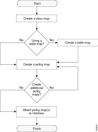
For more information on class maps and policy maps, see the "MQC and Network Traffic Marking" section.
For more information on table maps, see the "Creating a Table Map for Marking Network Traffic" section.
For more information on completing the processes shown in this flow chart, see the "How to Mark Network Traffic" section.
MQC and Network Traffic Marking
To configure network traffic marking, you use the Modular Quality of Service (QoS) Command-Line Interface (CLI) (MQC).
The MQC is a CLI structure that allows you to complete the following tasks:
•
•
•
For more information about the MQC, see the "Modular Quality of Service Command-Line Interface" section of the Cisco IOS Quality of Service Solutions Configuration Guide, Release 12.3.
Traffic Classification Compared with Traffic Marking
Traffic classification and traffic marking are closely related and can be used together. Traffic marking can be viewed as an additional action, specified in a policy map, to be taken on a traffic class.
Traffic classification allows you to organize into traffic classes on the basis of whether the traffic matches specific criteria. For example, all traffic with a CoS value of 2 is grouped into one class, and traffic with DSCP value of 3 is grouped into another class. The match criterion is user-defined.
After the traffic is organized into traffic classes, traffic marking allows you to mark (that is, set or change) an attribute for the traffic belonging to that specific class. For instance, you may want to change the CoS value from 2 to 1, or you may want to change the DSCP value from 3 to 2.
The match criteria used by traffic classification are specified by configuring a match command in a class map. The marking action taken by traffic marking is specified by configuring a set command in a policy map. These class maps and policy maps are configured using the MQC.
Table 4 compares the features of traffic classification and traffic marking.
How to Mark Network Traffic
This section contains the following procedures.
•
•
•
•
•
Creating a Class Map for Marking Network Traffic
In this procedure, you create a class map to define traffic classes. Within the class map, the appropriate match command is used to specify the matching criteria for the traffic classes.
To create the class map and specify the matching criteria, complete the following steps.
SUMMARY STEPS
1.
2.
3.
4.

Note
5.
DETAILED STEPS
Creating a Table Map for Marking Network Traffic
Note
The table map contains the mapping scheme used for establishing the to-from relationship and equivalency between one traffic-marking value and another.
The table map can be configured for use with multiple policy maps. The policy maps can then be configured to convert and propagate the traffic-marking values defined in the table map. Then the policy maps can be attached to the input or output interface of either the ingress or egress router, as appropriate to serve the QoS requirements of your network.
To create and configure the table map, complete the following steps.
SUMMARY STEPS
1.
2.
3.
4.
DETAILED STEPS
Creating a Policy Map for Applying a QoS Feature to Network Traffic
In this procedure, you create and configure a policy map to use the class map (or the table map). The policy map applies the appropriate QoS feature to the network traffic based on the traffic classification.
To create a policy map, complete the following steps.
Restrictions
•
–
–
–
•
•
•
•
SUMMARY STEPS
1.
2.
3.
4.
5.
Note
or
set cos dscp table table-map-name
Note
6.
7.
or
show policy-map policy-map class class-name
8.
DETAILED STEPS
Step 1
enable
Example:Router> enable
Enables privileged EXEC mode.
•
Step 2
configure terminal
Example:Router# configure terminal
Enters global configuration mode.
Step 3
policy-map policy-map-name
Example:Router(config)# policy-map policy1
Specifies the name of the policy map created earlier and enters policy-map configuration mode.
•
Step 4
class {class-name | class-default}
Example:Router(config-pmap)# class class1
Specifies the name of the class whose policy you want to create and enters policy-map class configuration mode. This class is associated with the class map created earlier.
•
Step 5
set cos cos-value
(Optional) Sets the CoS value in the type of service (ToS) byte.
Note
or
or
set cos dscp table table-map-name
(Optional) If a table map has been created earlier, sets the CoS value based on the DSCP value (or action) defined in the table map.
Note
Router(config-pmap-c)# set cos 2
or
Router(config-pmap-c)#
set cos dscp table table-map1Step 6
end
Example:Router(config-pmap-c)# end
Returns to privileged EXEC mode.
Step 7
show policy-map
(Optional) Displays all configured policy maps.
or
or
show policy-map policy-map class class-name
(Optional) Displays the configuration for the specified class of the specified policy map.
•
Router# show policy-map
or
Router#show policy-map policy1 class class7Step 8
exit
Example:Router# exit
(Optional) Exits privileged EXEC mode.
What To Do Next
Create and configure as many policy maps as you need for your network. To create and configure additional policy maps, repeat the steps in the "Creating a Policy Map for Applying a QoS Feature to Network Traffic" section. Then attach the policy maps to the appropriate interface, following the instructions in the "Attaching the Policy Map to an Interface" section.
Attaching the Policy Map to an Interface
After you create the policy map, you must attach it to an interface. Policy maps can be attached to either the input or output direction of the interface.
Note
To attach the policy map, complete the following steps.
SUMMARY STEPS
1.
2.
3.
4.
5.
6.
7.
8.
9.
DETAILED STEPS
Step 1
enable
Example:Router> enable
Enables privileged EXEC mode.
•
Step 2
configure terminal
Example:Router# configure terminal
Enters global configuration mode.
Step 3
interface type number [name-tag]
Example:Router(config)# interface serial4/0
Configures an interface type and enters interface configuration mode.
•
Step 4
pvc [name] vpi/vci [ilmi |qsaal |smds | l2transport]
Example:Router(config-if)# pvc cisco 0/16
(Optional) Creates or assigns a name to an ATM permanent virtual circuit (PVC), specifies the encapsulation type on an ATM PVC, and enters ATM virtual circuit configuration mode.
•
Note
Step 5
exit
Example:Router(config-atm-vc)# exit
(Optional) Returns to interface configuration mode.
Note
Step 6
service-policy {input | output} policy-map-name
Example:Router(config-if)# service-policy input policy1
Attaches a policy map to an input or output interface.
•
Note
Step 7
end
Example:Router(config-if)# end
Returns to privileged EXEC mode.
Step 8
show policy-map interface interface-name
Example:
Router#show policy-map interface serial4/0(Optional) Displays the traffic statistics of all classes that are configured for all service policies either on the specified interface or subinterface or on a specific PVC on the interface.
•
Step 9
exit
Example:Router# exit
(Optional) Exits privileged EXEC mode.
Configuring QoS When Using IPSec VPNs
Note
To configure QoS when using IPSec VPNs, complete the following steps.
SUMMARY STEPS
1.
2.
3.
4.
5.
6.
7.
DETAILED STEPS
Configuration Examples for Marking Network Traffic
This section contains the following examples:
•
•
•
•
•
Creating a Class Map for Marking Network Traffic: Example
The following is an example of creating a class map to be used for marking network traffic. In this example, a class called class1 has been created. The traffic with a Frame Relay DLCI value of 500 will be put in this class.
Router> enable
Router# configure terminal
Router(config)# class-map class1
Router(config-cmap)# match fr-dlci 500
Router(config-cmap)# end
Creating a Table Map for Marking Network Traffic: Example
In the following example, the table-map (value mapping) command has been used to create and configure a table map called table-map1. This table map will be used to establish a to-from relationship between one traffic-marking value and another.
In table-map1, a traffic-marking value of 0 will be mapped to a value of 1.
Router> enableRouter# configure terminalRouter(config)# table-map table-map1 map from 0 to 1Router(config-tablemap)#
exitCreating a Policy Map for Applying a QoS Feature to Network Traffic: Examples
Policy Map Configured to Use set Command
The following is an example of creating a policy map to be used for traffic marking. In this example, a policy map called policy1 has been created, and the set dscp command has been configured for class1.
Router> enableRouter# configure terminalRouter(config)# policy-map policy1Router(config-pmap)# class class1Router(config-pmap-c)# set dscp 2Router(config-pmap-c)# endRouter#show policy-map class1Router# exitPolicy Map Configured to Use a Table Map
A policy map called policy2 has been created and configured to use table-map1 for setting the precedence value. In this example, the CoS value will be set according to the DSCP value defined in table-map1 created previously.
Router(config)# policy map policy1
Router(config-pmap)# class class-default
Router(config-pmap-c)#
set cos dscp table table-map1Router(config-pmap-c)#
exit
Note
When the DSCP value is copied and used for the CoS value only the first 3 bits (that is, the class selector bits) of the DSCP value will be used to set the CoS value. For example, if the DSCP value is EF (101110), the first 3 bits of this DSCP value will be used to set the CoS value, resulting in a CoS value of 5 (101).
Policy Map Configured to Use a Table Map for Mapping MLSP EXP Values
This section contains an example of a policy map configured to map MPLS experimental (EXP) values. Figure 2 illustrates the network topology for this configuration example.
Figure 2 Network Topology for Mapping MPLS EXP Value
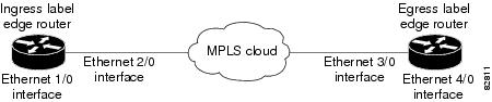
For this configuration example, traffic arrives at the input interface (an Ethernet 1/0 interface) of the ingress label edge router (LER). The precedence value is copied and used as the MPLS EXP value of the traffic when the MPLS label is imposed. This label imposition takes place at the ingress LER.
The traffic leaves the ingress LER through the output interface (an Ethernet 2/0 interface), traverses through the network backbone into the MPLS cloud, and enters the egress LER.
At the input interface of the egress LER (an Ethernet 3/0 interface), the MPLS EXP value is copied and used as the QoS group value. At the output interface of the egress LER (an Ethernet 4/0 interface), the QoS group value is copied and used as the precedence value.
To accomplish configuration described above, three separate policy maps were required—policy1, policy2, and policy3. Each policy map is configured to convert and propagate different traffic-marking values.
The first policy map, policy1, is configured to copy the precedence value of the traffic and use it as the MPLS EXP value during label imposition.
Router(config)# policy map policy1
Router(config-pmap)# class class-default
Router(config-pmap-c)#
set mpls experimental imposition precedenceRouter(config-pmap-c)#
exitWhen the traffic leaves the LER through the output interface (the Ethernet 2/0 interface), the MPLS EXP value is copied from the precedence value during MPLS label imposition. Copying the MPLS EXP value from the precedence value ensures that the MPLS EXP value reflects the appropriate QoS treatment. The traffic now proceeds through the MPLS cloud into the egress LER.
A second policy map called policy2 has been configured to copy the MPLS EXP value in the incoming MPLS traffic to the QoS group value. The QoS group value is used for internal purposes only. The QoS group value can be used with output queueing on the output interface of the egress router. The QoS group value can also be copied and used as the precedence value, as traffic leaves the egress LER through the output interface (the Ethernet 4/0 interface).
Router(config)# policy map policy2
Router(config-pmap)# class class-default
Router(config-pmap-c)#
set qos-group mpls experimental topmostRouter(config-pmap-c)#
exitA third policy map called policy3 has been configured to copy the internal QoS group value (previously based on the MPLS EXP value) to the precedence value. The QoS group value will be copied to the precedence value as the traffic leaves the egress LER through the output interface.
Router(config)# policy map policy3
Router(config-pmap)# class class-default
Router(config-pmap-c)#
set precedence qos-groupRouter(config-pmap-c)#
exitConfiguring these policy maps as shown (and attaching them to interfaces as shown in "Attaching the Policy Map to an Interface: Example" section), causes the appropriate quality of service treatment to be preserved for the traffic as the traffic progresses along an IP network, through an MPLS cloud, and back again into an IP network.
Note
In the MPLS configuration example, a table map was not created, and the set commands were configured without specifying the table keyword and table-map-name argument (for example, set precedence qos-group).
When the set commands are configured without specifying the table keyword and table-map-name argument, the values are copied from the specified categories. In this case, the QoS group value was copied and used to set the precedence value.
When the DSCP value is copied and used for the MPLS EXP value, only the first 3 bits (that is, the class selector bits) of the DSCP value will be used to set the MPLS value.
Attaching the Policy Map to an Interface: Example
The following is an example of attaching the policy map to the interface. In this example, the policy map called policy1 has been attached in the input direction of the Serial4/0 interface.
Router> enableRouter# configure terminalRouter(config)# interface serial4/0Router(config-if)# service-policy input policy1Router(config-if)# endRouter#show policy-map interface serial4/0Router# exitConfiguring QoS When Using IPSec VPNs: Example
The following is an example of configuring QoS when using IPSec VPNs. In this example, the crypto map command specifies the IPSec crypto map (mymap 10) to which the qos pre-classify command will be applied.
Router> enableRouter# configure terminalRouter(config)# crypto map mymap 10Router(config-crypto-map)# exitRouter(config)# interface serial4/0Router(config-if)# qos pre-classifyRouter(config-if)# exitAdditional References
The following sections provide references related to marking network traffic.
Related Documents
QoS commands: complete command syntax, command modes, command history, defaults, usage guidelines, and examples
Cisco IOS Quality of Service Solutions Command Reference, Release 12.3 T
MQC
"Modular Quality of Service Command-Line Interface" section of the Cisco IOS Quality of Service Solutions Configuration Guide, Release 12.3
CEF
Cisco IOS Switching Services Configuration Guide, Release 12.3
Classifying network traffic
IPSec and VPNs
Cisco IOS Security Configuration Guide, Release 12.3
Committed Access Rate (CAR)
"Classification" section of the Cisco IOS Quality of Service Solutions Configuration Guide, Release 12.3
Policy-based routing
Cisco IOS Quality of Service Solutions Configuration Guide, Release 12.3
QoS policy propagation via Border Gateway Protocol (BGP)
Cisco IOS Quality of Service Solutions Configuration Guide, Release 12.3
Standards
No new or modified standards are supported, and support for existing standards has not been modified.
—
MIBs
RFCs
No new or modified RFCs are supported, and support for existing RFCs has not been modified.
—
Technical Assistance
Glossary
ATM—Asynchronous Transfer Mode. The international standard for cell relay in which multiple service types (such as voice, video, or data) are conveyed in fixed-length (53-byte) cells. Fixed-length cells allow cell processing to occur in hardware, thereby reducing transit delays. ATM is designed to take advantage of high-speed transmission media, such as E3, SONET, and T3.
CoS—class of service. An indication of how an upper-layer protocol requires a lower-layer protocol to treat its messages. A CoS definition comprises a virtual route number and a transmission priority field.
DLCI—data-link connection identifier. A value that specifies a PVC or a switched virtual circuit (SVC) in a Frame Relay network. In the basic Frame Relay specification, DLCIs are locally significant (connected devices might use different values to specify the same connection). In the Local Management Interface (LMI) extended specification, DLCIs are globally significant (DLCIs specify individual end devices).
IPSec—IP Security. A framework of open standards that provides data confidentiality, data integrity, and data authentication between participating peers. IPSec provides these security services at the IP layer. IPSec uses Internet Key Exchange (IKE) to handle the negotiation of protocols and algorithms based on local policy and to generate the encryption and authentication keys to be used by IPSec. IPSec can protect one or more data flows between a pair of hosts, between a pair of security gateways, or between a security gateway and a host.
LER—label edge router. LERs are typically used in a Multiprotocol Label Switching network.
MPLS—Multiprotocol Label Switching. A switching method that forwards IP traffic using a label. This label instructs the routers and the switches in the network where to forward the packets based on preestablished IP routing information
PVC—permanent virtual circuit (or connection). A virtual circuit that is permanently established. PVCs save bandwidth associated with circuit establishment and tear down in situations where certain virtual circuits must exist all the time. In ATM terminology, called a permanent virtual connection.
VPN—Virtual Private Network. A network that enables traffic to travel securely over a public or shared network. An IPSec VPN uses encryption and tunneling, encapsulating private IP packets into IPSec-encrypted packets to protect information at the IP level.
Note
Feature Information for Marking Network Traffic
Table 5 lists the features in this module and provides links to specific configuration information. Only features that were introduced or modified in Cisco IOS Releases 12.2(1)T or later appear in the table.
Not all commands may be available in your Cisco IOS software release. For details on when support for specific commands was introduced, see the command reference documents.
Cisco IOS software images are specific to a Cisco IOS software release, a feature set, and a platform. Use Cisco Feature Navigator to find information about platform support and Cisco IOS software image support. Access Cisco Feature Navigator at http://www.cisco.com/go/fn. You must have an account on Cisco.com. If you do not have an account or have forgotten your username or password, click Cancel at the login dialog box and follow the instructions that appear.
Note
Table 5 Feature Information for Marking Network Traffic
Enhanced Packet Marking
12.2(13)T
The Enhanced Packet Marking feature allows you to map and convert the marking of a packet from one value to another by using a kind of conversion chart called a table map. The table map establishes an equivalency from one value to another. For example, the table map can map and convert the class of service (CoS) value of a packet to the precedence value of the packet. This value mapping can be propagated for use on the network, as needed.
The following sections provide information about this feature:
•
QoS Packet Marking
12.2(8)T
The QoS Packet Marking feature allows you to mark packets by setting the IP precedence bit or the IP differentiated services code point (DSCP) in the Type of Service (ToS) byte, and associate a local QoS group value with a packet.
The following sections provide information about this feature:
•
Class-Based Marking
12.2(2)T
The Class-Based Packet Marking feature provides users with a user-friendly command-line interface (CLI) for efficient packet marking by which users can differentiate packets based on the designated markings.
The following sections provide information about this feature:
•
Quality of Service for Virtual Private Networks
12.2(2)T
The QoS for VPNs feature provides a solution for making Cisco IOS QoS services operate in conjunction with tunneling and encryption on an interface. Cisco IOS software can classify packets and apply the appropriate QoS service before the data is encrypted and tunneled. The QoS for VPN feature allows users to look inside the packet so that packet marking can be done based on original port numbers and based on source and destination IP addresses. This allows the service provider to treat mission critical or multi-service traffic with higher priority across their network.
The following sections provide information about this feature:
•

Copyright © 2005 Cisco Systems, Inc. All rights reserved.
This module first published May 2, 2005. Last updated May 2, 2005.
 Feedback
Contact Cisco
- Open a Support Case

- (Requires a Cisco Service Contract)
This Document Applies to These Products
- Collaboration Endpoints - Retired Products
- Conferencing - Retired Products
- Contact Center - Retired Products
- Optical Networking - Retired Products
- Routers - Retired Products
- Security - Retired Products
- Servers - Unified Computing (UCS) Retired Products
- Storage Networking Retired Products
- Switches - Retired Products
- Video - Retired Products
- Wireless - Retired Products