Configuring H.323 Gatekeepers and Proxies
Available Languages
Contents
- Configuring H.323 Gatekeepers and Proxies
- Prerequisites for Configuring H.323 Gatekeepers and Proxies
- Restrictions for Configuring H.323 Gatekeepers and Proxies
- How to Configure H.323 Gatekeepers and Proxies
- Configuring Hot Standby
- Configuring Gatekeeper Zones
- Restrictions for Gatekeeper Zones
- Information About Gatekeeper Zones
- Zone and Subnet Configuration
- Gateway Selection Process
- Redundant H.323 Zone Support
- Configuring Gatekeeper Zones
- Configuring Destination Zones
- Configuring Intergatekeeper Communication
- Configuring Intergatekeeper Communication Using DNS
- Configuring Intergatekeeper Communication Manually
- Configuring Gatekeeper Alias Registration and Address Resolution
- Alias Registration
- Address Resolution
- Request Processing
- Configuring Load Balancing with Alternate Gatekeepers
- Restrictions for Load Balancing with Alternate Gatekeepers
- Information About Load Balancing with Alternate Gatekeepers
- Configuring Load Balancing with Alternate Gatekeepers
- Verifying Load Balancing with Alternate Gatekeepers
- Configuring Remote Clusters
- Configuring Remote Clusters
- Verifying Remote Clusters
- Configuring Static Nodes
- Configuring AAA and RADIUS
- Configuring H.323 Users via RADIUS
- Configuring a RADIUS AAA Server
- Configuring User Activity for RADIUS
- Configuring Security and Authentication
- Restrictions for Security and Authentication
- Information About Security and Authentication
- Interzone ClearTokens
- Cisco Access Tokens
- Tokenless Call Authorization
- Configuring Domain Zones and the IZCT Password
- Verifying Domain Zones and IZCT Password
- Configuring Cisco Access Tokens
- Verifying Cisco Acess Tokens
- Configuring Tokenless Call Authorization
- Configuring the IP Access List
- Configuring IP-Access-List Security on the Gatekeeper
- Configuring E.164 Interzone Routing
- Information About E.164 Interzone Routing
- Configuring a Dialing Prefix for Each Gateway
- Configuring Gatekeeper Interaction with External Applications
- Configuring Gatekeeper-to-GKTMP Server Flow Control
- Verifying Gatekeeper-to-GKTMP Server Flow Control
- Setting the Retry Timer for Failed GKTMP Server Connections
- Verifying the Retry Timer for Failed GKTMP Server Connections
- Configuring Registration and Call Rejection
- Verifying Registration and Call Rejection
- Configuring Gatekeeper Proxied Access
- Verifying Gatekeeper Proxied Access
- Configuring a Forced Disconnect on a Gatekeeper
- Verifying a Forced Disconnect on a Gatekeeper
- Configuring an H.323 Proxy Server
- Proxy Inside the Firewall
- Proxy in Co-Edge Mode
- Proxy Outside the Firewall
- Proxy and NAT
- Configuring Quality of Service
- Prerequisites for QoS
- Information About QoS
- RSVP and IP Precedence
- Application-Specific Routing
- Configuring QoS Using a Multimedia Backbone
- Enabling the Proxy to Forward H.323 Packets
- Isolating the Multimedia Network
- Configuring QoS on a Proxy Without ASR
- Configuring QoS on a Proxy with ASR
- ASR Enabled on the Proxy Using One Type of Routing Protocol
- ASR Enabled on the Proxy Using Two Different Autonomous Systems
- Configuring Border Elements
- Configuring Endpoints
- Information About Endpoints
- Alternate Endpoints
- Carrier-Based Routing Without a GKTMP Application Server
- Additional Routes to Alternate Endpoints
- Nonavailability Information for Terminating Endpoints
- Endpoint-Based Call-Capacity Management
- Configuring Alternate Endpoints
- Verifying Alternate Endpoints
- Configuring Additional Routes to Alternate Endpoints
- Configuring Nonavailability Information for Terminating Endpoints
- Verifying the Sending of Nonavailability Information
- Configuring Endpoint-Based Call-Capacity Management
- Forcing Endpoint Unregistration
- Prerequisites for Forcing Unregistration
- Verifying Endpoint Unregistration
- Configuring the IRR Timer and Disable IRQ Requests
- Restrictions for the IRR Timer and Disable IRQ Requests
- Information About the IRR Timer and Disable IRQ Requests
- Configuring IRR Periodic Intervals on the Gatekeeper
- Disabling IRQ Requests for All Calls in the Gatekeeper
- Configuring Sequential LRQs
- Restrictions for Sequential LRQs
- Information About Sequential LRQs
- Call Flow Using Sequential LRQ Enhancement Feature
- Configuring Sequential LRQ Enhancement
- Configuring the Sequential LRQ Timer
- Verifying Sequential LRQ Enhancement
- Configuration Examples for H.323 Gatekeepers and Proxies
- HSRP Example
- Gatekeeper Zones Example
- Load Balancing with Alternate Gatekeepers Example
- Security and Authentication Example
- Domain Zones and the IZCT Password
- Cisco Access Tokens
- Tokenless Call Authorization
- E.164 Interzone Routing Example
- Interaction with External Applications Example
- Proxy Use Example
- Co-Edge Proxy Example
- Endpoints Example
- IRR Timer and Disable IRQ Requests Example
- Sequential LRQ Enhancement Example
- Additional References
Configuring H.323 Gatekeepers and Proxies
This chapter describes how to configure Cisco H.323 gatekeepers. It also presents information about gatekeeper features that are not configurable.
Feature History for Configuring a Gatekeeper to Provide Nonavailability Information for Terminating Endpoints
Feature History for H.323 Version 2 Enhancements
| Release |
Modification |
|---|---|
| 12.0(5)T |
This feature was introduced. |
| 12.1(5)XM2 |
Support was added for the Cisco AS5350 and Cisco AS5400. |
| 12.2(2)XA |
The call rscmon update-timercommand was added. |
| 12.2(4)T |
The call rscmon update-timer command was integrated into this release. Support for the Cisco AS5300, Cisco AS5350, and Cisco AS5400 is not included. |
| 12.2(2)XB1 |
This feature was implemented on the Cisco AS5850. |
| 12.2(11)T |
This features was integrated into this release. |
Finding Support Information for Platforms and Cisco IOS Software Images
Use Cisco Feature Navigator to find information about platform support and Cisco IOS software image support. Access Cisco Feature Navigator at http://www.cisco.com/go/fn . You must have an account on Cisco.com. If you do not have an account or have forgotten your username or password, click Cancel at the login dialog box and follow the instructions that appear.
For more information about these and other related Cisco IOS voice features, see the following:
- "H.323 Overview" section
- For information about the full set of Cisco IOS voice features, see the entire Cisco IOS Voice Configuration Library--including library preface, glossary, and other documents--at http://www.cisco.com/en/US/docs/ios/12_3/vvf_c/cisco_ios_voice_configuration_library_glossary/vcl.htm
Prerequisites for Configuring H.323 Gatekeepers and Proxies
- Perform the prerequisites that are listed in the "Prerequisites for Configuring an H.323 Network" section.
- Install Cisco IOS Release 12.3 or later on your gatekeeper.
Restrictions for Configuring H.323 Gatekeepers and Proxies
Restrictions are described in the "Restrictions for Configuring an H.323 Network" section.
How to Configure H.323 Gatekeepers and Proxies
- Configuring Hot Standby
- Configuring Gatekeeper Zones
- Configuring Intergatekeeper Communication
- Configuring Gatekeeper Alias Registration and Address Resolution
- Configuring Load Balancing with Alternate Gatekeepers
- Configuring Remote Clusters
- Configuring Static Nodes
- Configuring AAA and RADIUS
- Configuring Security and Authentication
- Configuring E.164 Interzone Routing
- Configuring Gatekeeper Interaction with External Applications
- Configuring Gatekeeper Proxied Access
- Verifying Gatekeeper Proxied Access
- Configuring a Forced Disconnect on a Gatekeeper
- Verifying a Forced Disconnect on a Gatekeeper
- Configuring an H.323 Proxy Server
- Configuring Quality of Service
- Configuring Border Elements
- Configuring Endpoints
- Configuring the IRR Timer and Disable IRQ Requests
- Configuring Sequential LRQs
Configuring Hot Standby
Cisco routers support Hot Standby Router Protocol (HSRP), which allows one router to serve as a backup to another router. Cisco gatekeepers can be configured to use HSRP so that when one gatekeeper fails, the standby gatekeeper assumes its role.
To configure a gatekeeper to use HSRP, perform the following tasks.
DETAILED STEPS
What to Do Next
As long as both gatekeepers are up, the one with the higher priority on its HSRP interface is the active gatekeeper. If this active gatekeeper fails, or if its HSRP interface fails, the standby HSRP interface assumes the virtual HSRP address and, with it, the active gatekeeper role. When the gatekeeper with the higher HSRP priority comes back online, it reclaims the HSRP virtual address and the gatekeeper function, while the secondary gatekeeper goes back to standby status.
 Note |
Gatekeeper failover is not completely transparent to endpoints and gatekeepers. When the standby gatekeeper takes over, it does not have the state of the failed gatekeeper. If an endpoint that had registered with the failed gatekeeper now makes a request to the new gatekeeper, the gatekeeper responds with a reject, indicating that it does not recognize the endpoint. The endpoint must reregister with the new gatekeeper before it can continue H.323 operations. |
Configuring Gatekeeper Zones
- Restrictions for Gatekeeper Zones
- Information About Gatekeeper Zones
- Configuring Gatekeeper Zones
- Configuring Destination Zones
Restrictions for Gatekeeper Zones
- The gateway can register with only one gatekeeper at a time.
- Only E.164 address resolution is supported.
- Because the gateway can register with only one gatekeeper at a time, redundant H.323 zone support provides only redundancy and does not provide any load balancing.
- Although redundant H.323 zone support allows you to configure alternate gatekeepers, it does not insert information in the alternate gatekeeper field of some RAS messages.
Information About Gatekeeper Zones
Zone and Subnet Configuration
A zone is defined as the set of H.323 nodes controlled by a single gatekeeper. Gatekeepers that coexist on a network may be configured so that they register endpoints from different subnets.
Endpoints attempt to discover a gatekeeper and consequently the zone of which they are members by using the Registration, Admission, and Status (RAS) message protocol. The protocol supports a discovery message that may be sent multicast or unicast.
If the message is sent multicast, the endpoint registers nondeterministically with the first gatekeeper that responds to the message. To enforce predictable behavior, where endpoints on certain subnets are assigned to specific gatekeepers, the zone subnet command can be used to define the subnets that constitute a given gatekeeper zone. Any endpoint on a subnet that is not enabled for the gatekeeper is not accepted as a member of that gatekeeper zone. If the gatekeeper receives a discovery message from such an endpoint, it sends an explicit reject message.
Gateway Selection Process
Cisco H.323 Version 2 software improves the gateway selection process as follows:
- When more than one gateway is registered in a zone, the updated zone prefix command allows selection priorities to be assigned to these gateways on the basis of the dialed prefix.
- Gateway resource reporting allows the gateway to notify the gatekeeper when H.323 resources are getting low. The gatekeeper uses this information to determine which gateway to use to complete a call.
The gatekeeper maintains a separate gateway list, ordered by priority, for each of its zone prefixes. If a gateway does not have an assigned priority for a zone prefix, it defaults to priority 5, which is the median. To explicitly bar the use of a gateway for a zone prefix, the gateway must be defined as having a priority 0 for that zone prefix.
When selecting gateways, the gatekeeper identifies a target pool of gateways by performing a longest zone prefix match; then it selects from the target pool according to priorities and resource availability. If all high-priority gateways are busy, a low-priority gateway might be selected.
Redundant H.323 Zone Support
Redundant H.323 zone support allows for the following:
Gatekeeper Multiple Zone Support
Redundant H.323 zone support allows users to configure multiple remote zones to service the same zone or technology prefix. A user is able to configure more than one remote gatekeeper to which the local gatekeeper can send location requests (LRQs). This allows for more reliable call completion.
Redundant H.323 zone support is supported on all gatekeeper-enabled IOS images.
Zone Prefixes
The zone prefixes (typically area codes) serve the same purpose as the domain names in the H.323-ID address space.
For example, the local gatekeeper can be configured with the knowledge that zone prefix "212......" (that is, any address beginning "212" and followed by 7 arbitrary digits) is handled by the gatekeeper gatekeeper_2. Then, when the local gatekeeper is asked to admit a call to destination address 2125551111, it knows to send the LRQ to gatekeeper_2.
When gatekeeper_2 receives the request, the gatekeeper must resolve the address so that the call can be sent to its final destination. There may be an H.323 endpoint with that E.164 address that has registered with gatekeeper_2, in which case gatekeeper_2 returns the IP address for that endpoint. However, it is possible that the E.164 address belongs to a non-H.323 device (for example, a telephone or an H.320 terminal). Because non-H.323 devices do not register with gatekeepers, gatekeeper_2 cannot resolve the address. The gatekeeper must be able to select a gateway that can be used to reach the non-H.323 device. This is where the technology prefixes (or "gateway-type") become useful.
Technology Prefixes
The network administrator selects technology prefixes (tech-prefixes) to denote different types or classes of gateways. The gateways are then configured to register with their gatekeepers with these prefixes. For example, voice gateways can register with tech-prefix 1#, H.320 gateways with tech-prefix 2#, and voicemail gateways with tech-prefix 3#. More than one gateway can register with the same type prefix. When this happens, the gatekeeper makes a random selection among gateways of the same type.
If the callers know the type of device that they are trying to reach, they can include the technology prefix in the destination address to indicate the type of gateway to use to get to the destination. For example, if a caller knows that address 2125551111 belongs to a regular telephone, the destination address of 1#2125551111 can be used, where 1# indicates that the address should be resolved by a voice gateway. When the voice gateway receives the call for 1#2125551111, it strips off the technology prefix and bridges the next leg of the call to the telephone at 2125551111.
Configuring Gatekeeper Zones
DETAILED STEPS
| Command or Action | Purpose | |||
|---|---|---|---|---|
|
Step 1
|
gatekeeper
Example: Router(config)# gatekeeper |
Enters gatekeeper configuration mode. |
||
|
Step 2
|
zone local zone-name domain-name [ ras-ip-address ] [ port ]
Example: Router(config-gk)# zone local gk408or650 xyz.com |
Specifies a zone controlled by a gatekeeper. Arguments are as follows:
|
||
|
Step 3
|
zone remote zone-name domain-name ip-address [port] [cost cost [priority priority]]
Example: Router(config-gk)# zone remote zone1 domain 192.168.0.0 123 cost 25 priority 25 |
Defines the remote zone cluster. Keywords and arguments are as follows:
When several remote zones are configured, you can rank them by cost and priority value. A zone with a lower cost value and a higher priority value is given preference over others. |
||
|
Step 4
|
zone prefix gatekeeper-name e164-prefix [blast | seq] [gw-priority priority gw-alias [gw-alias, ...]]
Example: Router(config-gk)# zone prefix gatekeeper1 888 blast |
Adds a prefix to the gatekeeper zone list. For redundant H.323 zone support, you can configure multiple remote gatekeepers for the same prefix, but only one of the gatekeepers defined for any given zone prefix can be local. It is recommended that you limit the number of remote gatekeepers that serve the same zone prefix to two. By default, LRQs are sent sequentially to the remote gatekeepers. With sequential, LRQs are sent one at a time with a delay between them. With blast, LRQs are sent back-to-back in rapid sequence without delay. If you want to specify blast for each gatekeeper, you need to specify blast on only one zone prefix command per E.164 prefix. The order in which zone and technology prefixes are configured determines the order in which LRQs are sent to the remote gatekeepers. Using zone prefixes as an example, the local gatekeeper routes a call to the first zone that responds with an LCF. If the local gatekeeper is configured for a zone prefix that already has remote gatekeepers configured, the local gatekeeper automatically puts that zone prefix at the top of the list. |
||
|
Step 5
|
use-proxy local-zone remote-zone zone-name outbound-from gateway
Example: Router(config-gk)# use-proxy zone123 remote-zone remote456 outbound-from gateway |
Specifies that all calls originating from gateways in the local zone and bound to the remote zone route through a proxy, which should be registered with the gatekeeper. Keywords and arguments are as follows:
|
||
|
Step 6
|
zone subnet local-gatekeeper-name [ default | subnet-address {/ bits-in-mask |mask} enable ]
Example: Router(config-gk)# zone subnet gatekeeper3 default |
Defines a set of subnets that constitute the gatekeeper zone. Enables the gatekeeper for each of these subnets and disables it for all other subnets. (Repeat for each subnet.) Keywords and arguments are as follows:
To define the zone as being all but one set of subnets by disabling that set and enabling all other subnets, use the no form of the command as follows: Configure no zone subnet local-gatekeeper-name subnet-address {/ bits-in-mask | mask} enable. To accept the default behavior, which is that all subnets are enabled, use the no form of the command as follows: no zone subnet local-gatekeeper-name default enable. You can use this command more than once to create a list of subnets controlled by a gatekeeper. The subnet masks need not match actual subnets in use at your site. For example, to specify a particular endpoint, show its address as a 32-bit netmask. If a local gatekeeper name is contained in the message, it must match the local-gatekeeper-name argument.
|
||
|
Step 7
|
Repeat Step 6 for each subnet.
|
-- |
||
|
Step 8
|
no shutdown
Example: Router(config-gk)# no shutdown |
Brings the gatekeeper online. |
||
|
Step 9
|
exit
Example: Router(config-gk)# exit |
Exits the current mode. |
Configuring Destination Zones
When a gatekeeper receives an admission request (ARQ) message from a local zone gateway, if bandwidth management is enabled in the gatekeeper checks the bandwidth. The gatekeeper sends an admission reject (ARJ) message to the local zone gateway if the local zone is out of bandwidth and if no remote zone has been configured. The ARJ reject reason is set to "resource unavailable."
If a remote zone has been configured, the gatekeeper sends a location request (LRQ) message to that zone. A check is made of the total, interzone, and session bandwidth limits of the remote zone. If no remote zone has been defined or if the gatekeeper receives location request reject (LRJ) messages from all the remote gateways to which it has sent LRQ messages, the gatekeeper sends an ARJ message (with the reject reason set to "resource unavailable") to the requesting gateway.
Note |
The ARJ message functionality is available for only tech and zone prefix routing. By default, this functionality is not enabled. |
In addition to the gatekeeper maintaining concurrent call counts per zone, after receiving ARQ and LRQ messages from a requesting gateway, the gatekeeper can also check the concurrent call count of the destination zone. If the call count exceeds a preconfigured maximum threshold and if no other remote zone has been configured, the gatekeeper sends an ARJ or LRJ message to the requesting gateway. The ARJ reject reason is shown as "resource unavailable" and the LRJ reject reason is shown as "undefined reason."
If a remote zone has been configured, the gatekeeper sends LRQ messages to the remote zones. If no remote zone has been defined or if the gatekeeper receives LRJ messages from all the remote gateways to which it has sent LRQ messages, the gatekeeper sends an ARJ message (with the reject reason set to "resource unavailable") and an LRJ message (with the reject reason set to "undefined reason") to the requesting gateway.
After receiving an ARQ message from a requesting gateway and if the destination is a local zone, the gatekeeper sends an ACF message to the requesting gateway only if the local destination gateway has resources.
If the local destination gateway is out of resources, the gatekeeper tries to send an LRQ message to remote destination zones until it receives a location confirmation (LCF) message or until no remote zones remain. If no remote zone has been defined or if the gatekeeper receives LRJ messages from remote destinations for all the LRQ messages sent, the gatekeeper sends an ARJ message to the requesting gateway. The reject reason in the ARJ message to the requesting gateway is set to "resource unavailable."
To configure session bandwidth limits of the destination zones and how the gateway should handle requests if resources run low, use the following commands beginning in global configuration mode.
DETAILED STEPS
| Command or Action | Purpose | |
|---|---|---|
|
Step 1
|
gatekeeper
Example: Router(config)# gatekeeper |
Enters gatekeeper configuration mode. |
|
Step 2
|
bandwidth check-destination
Example: Router config-gk)# bandwidth check-destination |
Specifies the maximum aggregate bandwidth for H.323 traffic and enables destination bandwidth checking. |
|
Step 3
|
arq reject-resource-low
Example: Router(config-gk)# arq reject-resource-low |
(Optional) Configures the gatekeeper to reject an admissions request (ARQ) from a requesting gateway if resources run low. |
|
Step 4
|
exit
Example: Router(config-gk)# exit |
Exits the current mode. |
Configuring Intergatekeeper Communication
You can configure intergatekeeper communication either by means of DNS or manually.
- Configuring Intergatekeeper Communication Using DNS
- Configuring Intergatekeeper Communication Manually
Configuring Intergatekeeper Communication Using DNS
To configure intergatekeeper communication using DNS, use the following commands in global configuration mode.
DETAILED STEPS
| Command or Action | Purpose | |||
|---|---|---|---|---|
|
Step 1
|
ip name-server dns-servername [ server-address2...server-address6 ]
Example: Router(config)# ip name-server 192.168.0.0 192.168.1.1 |
Specifies the DNS server address. Arguments are as follows:
|
||
|
Step 2
|
ip domain-name name
Example: Router(config)# ip domain-name cisco.com |
Defines a default domain name that Cisco IOS software uses to complete unqualified host names (names without a dotted-decimal domain name). The argument is as follows:
|
||
|
Step 3
|
ras [gk-id@] host [:port] [priority]
|
For all gatekeepers in the system, enter a text record of the form into DNS. Arguments are as follows:
|
How you enter the text record for a particular domain depends on the DNS implementation. The following examples are for the Berkeley Internet Name Domain (BIND). These records are typically entered into the "hosts" database:
zone1.comintxt"ras gk.zone1.com"
zone2.comintxt"ras gk2@gk.zone2.com"
zone3.comintxt"ras gk.3@gk.zone3.com:1725"
zone4.comintxt"ras gk4@gk.zone4.com:1725 123"
zone5.comintxt"ras gk5@101.0.0.1:1725"
Configuring Intergatekeeper Communication Manually
If you choose not to use DNS or if DNS is not available, configure intergatekeeper communication manually. To configure intergatekeeper manual communication, use the following command in gatekeeper configuration mode for every other gatekeeper in the network.
DETAILED STEPS
| Command or Action | Purpose | |
|---|---|---|
|
Step 1
|
gatekeeper
Example: Router(config)# gatekeeper |
Enters gatekeeper configuration mode. |
|
Step 2
|
zone remote other-gatekeeper-name other-domain-name other-gatekeeper-address [port]
Example: Router(config-gk)# zone remote gatekeeper4 xxx.com 192.168.0.0 |
Statically specifies a remote zone if Domain Name System (DNS) is unavailable or undesirable. Enter this command for each gatekeeper. Arguments are as follows:
|
|
Step 3
|
exit
Example: Router(config-gk)# exit |
Exits the current mode. |
Configuring Gatekeeper Alias Registration and Address Resolution
You can configure multiple prefixes for a local zone and register an endpoint belonging to multiple zone prefixes. Gatekeepers can accept a registration request (RRQ) message with multiple E.164 aliases with different prefixes.
Alias Registration
When a gatekeeper receives an RRQ message from a gateway with a Foreign Exchange Station (FXS) port configured to register its E.164 address, it performs either of the following steps:
- If the E.164 alias is prefix-qualified, the gatekeeper tries to match the prefix with the zone prefixes it has defined. If a prefix is found, the gatekeeper searches its E.164 alias table with the exact alias from the RRQ message, including the prepended prefix, to make sure the alias is unique.
- If no zone prefix is found, the gatekeeper searches its E.164 alias table with the exact alias from the RRQ message:
- If the alias does exist and it is not owned by the same endpoint, the gatekeeper sends a registration reject (RRJ) message.
- If the alias does not exist, the gatekeeper creates an entry in the table for the exact alias name from the RRQ message, with or without the prefix qualifier, and sends a registration confirm (RCF) message.
Note |
With the Gatekeeper Alias Registration and Address Resolution Enhancements feature, the gatekeeper creates an entry in its E.164 alias table for the exact alias name from the RRQ message. It does not strip off the prefix before creating the entry. |
Address Resolution
Resolution for ARQ Messages
When a gatekeeper receives an admission request (ARQ) message from a gateway, it performs either of the following steps:
- If there is a technology prefix specified in the admission request and it is a hopoff technology prefix, the gatekeeper sends a location request (LRQ) message.
- If there is no technology prefix or the technology prefix is not a hopoff technology prefix, the gatekeeper uses the exact E.164 alias in the ARQ message, including the zone prefix, if any, to search its zone prefix table and the E.164 aliases registered by local endpoints:
- If no zone-prefix match is found and the arq reject-unknown prefix command is set, the gatekeeper sends an admission reject (ARJ) message.
- If a match is found and the destination zone is not local, the gatekeeper sends an LRQ message to the remote zone.
- If the destination address is an E.164 alias registered by an endpoint, the gatekeeper sends an admission confirm (ACF) message
- If the destination zone is local and the destination address is not registered but the local gateway is found with the specified technology prefix or the default technology prefix, the gatekeeper sends an ACF. If no local gateway with the specified technology prefix is found, the gatekeeper sends an ARJ message.
If there is no matching technology prefix and no default technology prefix is set, the gatekeeper sends an ARJ message.
Resolution for LRQ Messages
When a gatekeeper receives an LRQ message from a gateway, it performs either of the following steps:
- 'If a hopoff technology prefix is found in the Location Request and the destination zone is not local, the gatekeeper sends an LRQ message, if the lrq forward-queries command is set.
- If there is no technology prefix or the technology prefix is not a hopoff technology prefix, the gatekeeper uses the exact E.164 alias in the LRQ message to search its zone prefix table and the registered E.164 aliases.
- If no match is found and the lrq reject-unknown prefix command is set, the gatekeeper sends a location reject (LRJ) message.
- If a match is found and the destination zone is a remote zone, and the lrq forward-queries command is set, the gatekeeper sends an LRQ message to the destination zone.
- If the destination zone is local and the destination address is registered, the gatekeeper sends a location confirm (LCF) message.
- If the destination zone is local and the destination address is not registered but the local gateway is found with the specified technology prefix or the default technology prefix, the gatekeeper sends an LCF message. If no local gateway with the specified technology prefix is found, the gatekeeper sends an LRJ message.
- If the destination zone is local and the destination address is not registered, and there is no matching technology prefix and no default technology prefix is set, the gatekeeper sends an LRJ message.
Request Processing
A gatekeeper with the Gatekeeper Alias Registration and Address Resolution Enhancements feature processes requests in a new way, as showing in the following examples. The gatekeeper is configured with two local zones, zone1 and zone2, and three prefixes, as follows:
Router(config-gk)#zone local zone1 domain.com
Router(config-gk)#zone local zone2 domain.com
Router(config-gk)#zone prefix zone2 407 .......
Router(config-gk)#zone prefix zone1 408 .......
Router(config-gk)#zone prefix zone1 409 .......
The table below shows various E.164 alias registration requests and the resulting gatekeeper actions.
| Table 1 | E.164 Alias Registration Requests and Gatekeeper Actions |
| RRQ |
Without This Feature |
With This Feature |
Action |
|---|---|---|---|
| 4085551000 4095552000 |
RRJ |
RCF |
Two entries are created in the E.164 alias hash table: 4085551000 4095552000 |
| 4095551000 |
RCF |
RCF |
4095551000 is created in the table. |
| 4085553000 |
RCF |
RCF |
4085553000 is created in the table. |
| 5551234 |
RRJ |
RCF |
5551234 is created in the table. |
| 4085551000 |
RRJ |
RRJ |
Gatekeeper rejects the request because it is a duplicate alias. |
| 4085554000 4075554000 |
RRJ |
RRJ |
Gatekeeper rejects the request because the two prefixes (407 and 408) have different zone names (zone1 and zone2). |
To allow endpoints to communicate between zones, gatekeepers must be able to determine which zone an endpoint is in and be able to locate the gatekeeper responsible for that zone. If the Domain Name System (DNS) mechanism is available, a DNS domain name can be associated with each gatekeeper.
Note |
For more information on DNS, see the "Configuring Intergatekeeper Communication" section. |
Configuring Load Balancing with Alternate Gatekeepers
This section contains the following information:
- Restrictions for Load Balancing with Alternate Gatekeepers
- Information About Load Balancing with Alternate Gatekeepers
- Configuring Load Balancing with Alternate Gatekeepers
- Verifying Load Balancing with Alternate Gatekeepers
Restrictions for Load Balancing with Alternate Gatekeepers
- The gatekeeper-to-gatekeeper redundancy and load-sharing mechanism requires the Cisco H.323 VoIP Gatekeeper for Cisco Access Platforms feature.
- The order in which LRQs are sent to the gatekeepers is based on the order in which the gatekeepers are listed. You cannot specify a priority number for a gatekeeper.
- Regardless of the order in which the LRQs are sent, the gateway still uses the first gatekeeper that sends an LCF.
- The settings for delay between LRQs and the LRQ window are global and cannot be set on a per-zone or technology-prefix basis.
- The number of remote gatekeepers multiplied by the delay per LRQ cannot exceed the Routing Information Protocol (RIP) timeout. Therefore, we recommend that you limit your list of remote gatekeepers to two or three.
- If LRQ forwarding is enabled on the directory gatekeeper, the sequential setting for LRQs is ignored.
- Only E.164 address resolution is supported.
- Using redundant H.323 zone support in the "directory gatekeeper" can generate extra RAS messages. Therefore, the number of "directory gatekeeper" levels should be kept to a minimum (two or three at the maximum).
- If a gatekeeper fails, the endpoint might use alternate gatekeepers to continue operation. The example below creates a local cluster associated with a local zone and defines an alternate gatekeeper within the cluster.
Information About Load Balancing with Alternate Gatekeepers
Load balancing allows the gatekeeper to move registered H.323 endpoints to an alternate gatekeeper or to reject new calls and registrations once a certain threshold is met.
If a gatekeeper fails, the endpoint might use alternate gatekeepers to continue operation.
The gatekeeper-to-gatekeeper redundancy and load-sharing mechanism expands the capability that is provided by the redundant H.323 zone support feature. Redundant H.323 zone support allows you to configure multiple gatekeepers to service the same zone or technology prefix by sending LRQs to two or more gatekeepers.
With the redundant H.323 zone support feature, the LRQs are sent simultaneously (in a "blast" fashion) to all of the gatekeepers in the list. The gateway registers with the gatekeeper that responds first. Then, if that gatekeeper becomes unavailable, the gateway registers with another gatekeeper from the list.
The gatekeeper-to-gatekeeper redundancy and load-sharing mechanism allows you to configure gatekeeper support and to give preference to specific gatekeepers. You may choose whether the LRQs are sent simultaneously or sequentially (one at a time) to the remote gatekeepers in the list. If the LRQs are sent sequentially, a delay is inserted after the first LRQ and before the next LRQ is sent. This delay allows the first gatekeeper to respond before the LRQ is sent to the next gatekeeper. The order in which LRQs are sent to the gatekeepers is based on the order in which the gatekeepers are listed (using either the zone prefix command or the gw-type-prefix command).
Once the local gatekeeper has sent LRQs to all the remote gatekeepers in the list (either simultaneously or sequentially), if it has not yet received a location confirmation (LCF), it opens a "window." During this window, the local gatekeeper waits to see whether a LCF is subsequently received from any of the remote gatekeepers. If no LCF is received from any of the remote gatekeepers while the window is open, the call is rejected.
Configuring Load Balancing with Alternate Gatekeepers
To configure load balancing and alternate gatekeepers, use the following commands beginning in global configuration mode.
DETAILED STEPS
| Command or Action | Purpose | |
|---|---|---|
|
Step 1
|
gatekeeper
Example: Router(config)# gatekeeper |
Enters gatekeeper configuration mode. |
|
Step 2
|
zone local local-zone-name domain-name [ras-ip-address]
Example: Router(config-gk)# zone local gk408or650 xyz.com |
Defines the gatekeeper's name or zone name. This is usually the fully domain-qualified host name of the gatekeeper. |
|
Step 3
|
zone cluster local cluster-name local-zone-name
Example: Router(config-gk)# zone cluster local RTPCluster RTPGK1 |
Defines a local cluster for the local zone. |
|
Step 4
|
element alternateGK ip-address [port]
Example: Router(config-gk-cluster)# element alternateGK1 192.168.0.0 |
Defines the alternate gatekeeper in the local cluster. The alternate gatekeeper is an alternate gatekeeper to the local zone. Arguments are as follows:
|
|
Step 5
|
exit
Example: Router(config-gk-cluster)# exit |
Exits the current mode. |
|
Step 6
|
load-balance [endpoints max-endpoints] [calls max-calls] [cpu max-%cpu] [memory max-%mem-used]
Example: Router(config-gk)# load-balance endpoints 200 calls 100 cpu 75 memory 80 |
Configures load balancing. Keywords and arguments are as follows:
|
|
Step 7
|
exit
Example: Router(config-gk)# exit |
Exits the current mode. |
Verifying Load Balancing with Alternate Gatekeepers
DETAILED STEPS
| Step 1 | show gatekeeper status Use this command to see if load balancing is configured and if accounting vendor-specific attributes (VSAs) are enabled. The last five lines shown below, starting with Load Balance Count, display only when load balancing is enabled. Example:
Router# show gatekeeper status
Gatekeeper State: UP
Load Balancing: ENABLED
Zone Name: RoseGK
Zone Name: PurpleGK
Accounting: DISABLED
Security: DISABLED
Maximum Remote Bandwidth: unlimited
Current Remote Bandwidth: 0 kbps
Current Remote Bandwidth (w/Alt GKs): 0 kbps
Load Balance Count: 0
Calls: 0/unlimited
Endpoints: 0/unlimited
Memory: 0%/90%
CPU: 0%/80%
|
| Step 2 | show gatekeeper performance statistics Use this command to verify performance statistics. Example:
Router# show gatekeeper performance statistics
Performance statistics captured since:19:00:12 EST Sun Feb 28 1993
RAS inbound message counters:
        Originating ARQ:426    Terminating ARQ:306    LRQ:154
RAS outbound message counters:
        ACF:731        ARJ:1  LCF:154        LRJ:0
        ARJ due to overload:0
        LRJ due to overload:0
Load balancing events:0
Real endpoints:5
|
Configuring Remote Clusters
The following commands define a group of associated gatekeepers in a remote cluster. This remote cluster can then be addressed using the zone prefix command in the same way that a remote gatekeeper would be addressed to route calls. However, rather than individually addressing each remote gatekeeper within the cluster, you can address the cluster as a single entity. Additionally, location requests (LRQs) are now sent round-robin to each gatekeeper within the remote cluster.
Configuring Remote Clusters
DETAILED STEPS
| Command or Action | Purpose | |||
|---|---|---|---|---|
|
Step 1
|
gatekeeper
Example: Router(config)# gatekeeper |
Enters gatekeeper configuration mode. |
||
|
Step 2
|
zone local zonename domainname [ras-ip-address] [port]
Example: Router(config-gk)# zone local gk408or650 xyz.com |
Defines the gatekeeper's name or zone name. |
||
|
Step 3
|
zone cluster remote remote-cluster-name domainname [cost cost [priority priority]]
Example: Router(config-gk)# zone cluster remote SJCluster cisco.com |
Defines a remote cluster. Keywords and arguments are as follows:
|
||
|
Step 4
|
element alternateGK IP-address [port]
Example: Router(config-gk-cluster)# element alternateGK1 192.168.0.0 |
Defines component elements of local or remote clusters. |
||
|
Step 5
|
exit
Example: Router(config-gk-cluster)# exit |
Exits the current mode. |
||
|
Step 6
|
zone prefix remote-clustername e164-prefix
Example: Router(config-gk)# zone prefix 40_gatekeeper 408* |
Keywords and arguments are as follows:
|
||
|
Step 7
|
exit
Example: Router(config-gk)# exit |
Exits the current mode. |
Verifying Remote Clusters
DETAILED STEPS
| Step 1 | show gatekeeper status cluster Use this command to display each element of a cluster. This command shows the health of the elements in a cluster and reports on the percentage of memory and CPU usage, the number of active calls, and the number of endpoints registered on the element. The Last Announce field tells you the time since the last announcement message was received from the alternate gatekeeper. In this example, MsPacman and LavenderGK are part of a local cluster. Example:
Router# show gatekeeper status cluster
CLUSTER INFORMATION
                   ===================
                             Active   Endpoint   Last
Hostname       %Mem   %CPU   Calls    Count      Announce
--------       ----   ----   ------   --------   --------
MsPacman       17     2      0        1          Local Host
LavenderGK     30     1      0        4          14s
|
| Step 2 | show gatekeeper zone status Use this command to display the bandwidth information for all zones. Example:
Router# show gatekeeper zone status
                         GATEKEEPER ZONES
                         ================
GK name      Domain Name   RAS Address     PORT  FLAGS
-------      -----------   -----------     ----- -----
RoseGK       cisco.com     209.165.201.30  1719  LS
  BANDWIDTH INFORMATION (kbps) :
    Maximum interzone bandwidth :unlimited
    Current interzone bandwidth :0
    Current interzone bandwidth (w/ Alt GKs) :0
    Maximum total bandwidth :unlimited
    Current total bandwidth :0
    Current total bandwidth (w/ Alt GKs) :0
    Maximum session bandwidth :unlimited
  SUBNET ATTRIBUTES :
    All Other Subnets :(Enabled)
  PROXY USAGE CONFIGURATION :
    Inbound Calls from all other zones :
      to terminals in local zone RoseGK :use proxy
      to gateways in local zone RoseGK  :do not use proxy
    Outbound Calls to all other zones :
      from terminals in local zone RoseGK :use proxy
      from gateways in local zone RoseGK  :do not use proxy
|
| Step 3 | show gatekeeper zone cluster Use this command to display information about alternate gatekeepers. PRI represents the priority value assigned to an alternate gatekeeper. This field ranges from 0 to 127, with 127 representing the lowest priority. Example:
Router# show gatekeeper zone cluster
ALTERNATE GATEKEEPER INFORMATION
================================
                                TOT BW   INT BW   REM BW   LAST      ALT GK
LOCAL GK NAME ALT GK NAME   PRI (kbps)   (kbps)   (kbps)   ANNOUNCE  STATUS
------------- -----------   --- ------   ------   ------   --------  ------
RoseGK        LilacGK       120   0        0        0        7s      CONNECTED
|
| Step 4 | show proxy h323 status Use this command to display information about the proxy such as the T.120 mode and what port is being used. Example:
Router# show proxy h323 status
        H.323 Proxy Status
        ==================
    H.323 Proxy Feature:Enabled
    Proxy interface = Ethernet0:UP
    Proxy IP address = 209.165.200.254
    Proxy IP port = 11720
    Application Specific Routing:Disabled
    RAS Initialization:Complete
    Proxy aliases configured:
      H323_ID:PROXY
    Proxy aliases assigned by Gatekeeper:
      H323_ID:PROXY
    Gatekeeper multicast discovery:Disabled
    Gatekeeper:
        Gatekeeper ID:DVM1
        IP address:209.165.200.254
    Gatekeeper registration succeeded
    T.120 Mode:PROXY
    RTP Statistics:OFF
    Number of calls in progress:0
|
| Step 5 | show gatekeeper cluster Use this command to display all clusters defined in the gatekeeper and with their component elements. Example: Router# show gatekeeper cluster gatekeeper zone local RTPGK1cisco.com zone cluster local RTPCluster RTPGK1 element RTPGK2 209.165.200 1719 element RTPGK3 209.165.200 1719 zone cluster remote SJCluster cisco.com element SJGK1 209.18.79.23 1719 element SJGK2 209.18.79.24 1719 element SJGK3 209.18.79.25 1719 no shutdown Router# show gatekeeper cluster CONFIGURED CLUSTERS =================== Cluster Name Type Local Zone Elements IP ------------ ---- ---------- -------- -- RTPCluster Local RTPGK1 RTPGK2 209.165.200.254 1719 RTPGK3 209.165.200.223 1719 SJCluster Remote SJGK1 209.165.200.257 1719 SJGK2 209.165.200.258 1719 SJGK3 209.165.200.259 1719 |
Configuring Static Nodes
In some cases, registration information is not accessible for a terminal or endpoint from any gatekeeper. This inaccessible registration information may be because the endpoint does not use RAS, is in an area where no gatekeeper exists, or is in a zone where the gatekeeper addressing is unavailable either through DNS or through configuration. These endpoints can still be accessed via a gatekeeper by entering them as static nodes.
To enter endpoints as static nodes, use the following commands beginning in global configuration mode.
DETAILED STEPS
| Command or Action | Purpose | |
|---|---|---|
|
Step 1
|
gatekeeper
Example: Router(config)# gatekeeper |
Enters gatekeeper configuration mode. |
|
Step 2
|
zone local gatekeeper-name domain-name [ras-ip-address]
Example: Router(config-gk)# zone local gatekeeper1 domain1 |
Specifies a zone controlled by a gatekeeper. |
|
Step 3
|
alias static ip-signaling-addr [ port ] gkid gatekeeper-name [ ras ip-ras-addr port ] [ terminal | mcu | gateway { h320 | h323-proxy | voip }] [ e164 e164-address ] [ h323id h323-id ]
Example: Router(config-gk)# alias static ip-signalling-addr gkid gatekeeper1 |
Creates a static entry in the local alias table for each E.164 address. Keywords and arguments are as follows:
|
|
Step 4
|
Repeat Step 3 for each E.164 address that you want to add for the endpoint.
|
-- |
|
Step 5
|
exit
Example: Router(config-gk)# exit |
Exits the current mode. |
Configuring AAA and RADIUS
Version 1 of the H.323 specification does not provide a mechanism for authenticating registered endpoints. Credential information is not passed between gateways and gatekeepers. However, by enabling AAA on the gatekeeper and configuring for RADIUS and TACACS+, a rudimentary form of identification can be achieved.
In Version 2 and higher, authentication is done using tokens. See the "Configuring Security and Authentication" section for more information.
If the AAA feature is enabled, the gatekeeper attempts to use the registered aliases along with a password and completes an authentication transaction to a RADIUS and TACACS+ server. The registration is accepted only if RADIUS and TACACS+ successfully authenticates the name.
The gatekeeper can be configured so that a default password can be used for all users. It can also be configured to recognize a password separator character that allows users to piggyback their passwords onto H.323-ID registrations. In this case, the separator character separates the ID and password fields.
Note |
The names loaded into RADIUS and TACACS+ are probably not the same names provided for dial access because they may all have the same password. |
If AAA is enabled on the gatekeeper, the gatekeeper emits an accounting record each time a call is admitted or disconnected.
- Configuring H.323 Users via RADIUS
- Configuring a RADIUS AAA Server
- Configuring User Activity for RADIUS
Configuring H.323 Users via RADIUS
Note |
For more information about configuring AAA services or RADIUS, see the Cisco IOS Security Configuration Guide at http://www.cisco.com/en/US/docs/ios/sec_user_services/configuration/guide/15_0/sec_user_services_15_0_book.html . |
To authenticate H.323 users via RADIUS, use the following commands beginning in global configuration mode.
DETAILED STEPS
| Command or Action | Purpose | |
|---|---|---|
|
Step 1
|
aaa new-model
Example: Router(config)# aaa new-model |
Enables the authentication, authorization, and accounting (AAA) access model. |
|
Step 2
|
aaa authentication login {default | listname} method1 [method2...]
Example: Router(config)# aaa authentication login default |
Sets AAA authentication at login. Keywords and arguments are as follows:
|
|
Step 3
|
radius-server host {hostname | ip-address}[auth-port port] [acct-port port] [timeout seconds] [retransmit retries] [key string]
Example: Router(config)# radius-server host 10.0.0.1 auth-port 1645 acct-port 1646 |
Specifies the RADIUS server host. Keywords and arguments are as follows:
|
|
Step 4
|
radius-server key { 0 string | 7 string | string }
Example: Router(config)# radius-server key 0 143212343 |
Sets the authentication and encryption key for all RADIUS communications between the router and the RADIUS daemon. Keywords and arguments are as follows:
|
|
Step 5
|
gatekeeper
Example: Router(config)# gatekeeper |
Enters gatekeeper configuration mode. |
|
Step 6
|
security {any | h323-id | e164} {password default password | password separator character}
Example: Router(config-gk)# security any password default thisismypassword |
Enables authentication and authorization on a gatekeeper and specifies the means of identifying the user to RADIUS/TACACS+. Keywords and arguments are as follows:
Note that passwords may be piggybacked only in the H.323-ID, not the E.164 address. This is because the E.164 address allows a limited set of mostly numeric characters. If the endpoint does not wish to register an H.323-ID, it can still supply an H.323-ID that consists of just the separator character and password. This is understood to be a password mechanism, and no H.323-ID is registered. |
|
Step 7
|
exit
Example: Router(config-gk)# exit |
Exits the current mode. |
|
Step 8
|
Enter each user into the RADIUS database.
|
Use either of the following:
|
Configuring a RADIUS AAA Server
To configure a RADIUS/AAA server with information about the gatekeeper for your network installation, use the following commands in global configuration mode.
DETAILED STEPS
| Command or Action | Purpose | |
|---|---|---|
|
Step 1
|
aaa new-model
Example: Router(config)# aaa new-model |
Enables the authentication, authorization, and accounting (AAA) model. |
|
Step 2
|
aaa authentication login { default | listname } method1 [ method2... ]
Example: Router(config)# aaa authentication login default |
Sets AAA authorization at login. For a list of keywords and arguments, see Configuring H.323 Users via RADIUS, Step 2. |
|
Step 3
|
radius-server deadtime minutes
Example: Router(config)# radius-server deadtime 120 |
Sets the time, in minutes, for which a RADIUS server is skipped over by transaction requests. Range: 1 to 1440 (24 hours). |
|
Step 4
|
radius-server host { hostname | ip-address } [ auth-port port ] [ acct-port port ] [ timeout seconds ] [ retransmit retries ] [ key string ]
Example: Router(config)# radius-server host 10.0.0.1 auth-port 1645 acct-port 1646 |
Specifies the RADIUS server host. For a list of keywords and arguments, see Configuring H.323 Users via RADIUS, Step 3. |
|
Step 5
|
radius-server key { 0 string | 7 string | string }
Example: Router(config) radius-server key 7 anykey |
Sets the authentication and encryption key for all RADIUS communications between the router and the RADIUS daemon. For a list of arguments, see Configuring H.323 Users via RADIUS Step 4. |
|
Step 6
|
Configure the CiscoSecure AAA server.
|
#Client Name       Key
#--------------    ----------
gk215.cisco.com    testing123
Where gk215.cisco.com is resolved to the IP address of the gatekeeper requesting authentication.
h323id@cisco.com  Password = "password"
User-Service-Type = Framed-User,
Login-Service = Telnet
Where h323id@cisco.com is the h323-id of the gateway authenticating to gatekeeper gk215.cisco.com. |
Configuring User Activity for RADIUS
After you enable AAA and configure the gateway to recognize RADIUS as the remote security server providing authentication services, the next step is to configure the gateway to report user activity to the RADIUS server in the form of connection accounting records.
To send connection accounting records to the RADIUS server, use the following commands beginning in global configuration mode.
DETAILED STEPS
| Command or Action | Purpose | |
|---|---|---|
|
Step 1
|
aaa accounting connection h323 { stop-only | start-stop | wait-start | none } [ broadcast ] group groupname
Example: Router(config)# aaa accounting connection h323 start-stop group group1 |
Defines the accounting method list H.323 with RADIUS as a method. Keywords and arguments are as follows:
|
|
Step 2
|
gatekeeper
Example: Router(config)# gatekeeper |
Enters gatekeeper configuration mode. |
|
Step 3
|
accounting
Example: Router(config-gk)# aaa accounting |
Enables authentication, authorization, and accounting (AAA) of requested services for billing or security purposes when you use RADIUS or TACACS+. |
|
Step 4
|
exit
Example: Router(config-gk)# exit |
Exits the current mode. |
Note |
For more information about AAA connection accounting services, see the Cisco IOS Security Configuration Guide at http://www.cisco.com/en/US/docs/ios/sec_user_services/configuration/guide/15_0/sec_user_services_15_0_book.html . |
Configuring Security and Authentication
This section contains the following information:
- Restrictions for Security and Authentication
- Information About Security and Authentication
- Configuring Domain Zones and the IZCT Password
- Verifying Domain Zones and IZCT Password
- Configuring Cisco Access Tokens
- Verifying Cisco Acess Tokens
- Configuring Tokenless Call Authorization
Restrictions for Security and Authentication
- CAT is a Cisco-proprietary security mechanism and requires a Cisco solution to receive the full end-to-end benefits of the Gatekeeper-to-Gatekeeper Authentication feature.
- LRQ message authentication is done on a hop-by-hop basis. Because a non-Cisco gatekeeper does not support CATs, authentication stops at the non-Cisco gatekeeper. If a non-Cisco gatekeeper can support LRQ forwarding, end-to-end authentication is achieved. However, LRQ message authentication is performed only at the Cisco gatekeepers.
- If IZCT is used for Clustered Gatekeepers, the same IZCT password should be used on all the Gatekeepers belonging to the same cluster
Information About Security and Authentication
This section contains the following information:
Interzone ClearTokens
The Inter-Domain Gatekeeper Security Enhancement provides a means of authenticating and authorizing H.323 calls between the administrative domains of Internet Telephone Service Providers (ITSPs).
An interzone ClearToken (IZCT) is generated in the originating gatekeeper when a location request (LRQ) is initiated or an admission confirmation (ACF) is about to be sent for an intrazone call within an ITSP's administrative domain. As the IZCT traverses through the routing path, each gatekeeper stamps the IZCT's destination gatekeeper ID with its own ID. This identifies when the IZCT is being passed over to another ITSP's domain. The IZCT is then sent back to the originating gateway in the location confirmation (LCF) message. The originating gateway passes the IZCT to the terminating gateway in the SETUP message.
The terminating gateway forwards the IZCT in the AnswerCall admission request (ARQ) to the terminating gatekeeper, which then validates it.
Within the IZCT format, the following information is required:
- srcCarrierID --Source carrier identification
- dstCarrierID -- Destination carrier identification
- intCarrierID -- Intermediate carrier identification
- srcZone -- Source zone
- dstZone -- Destination zone
- interzone type
The figure below shows a simple inter-ITSP diagram of the IZCT flow.
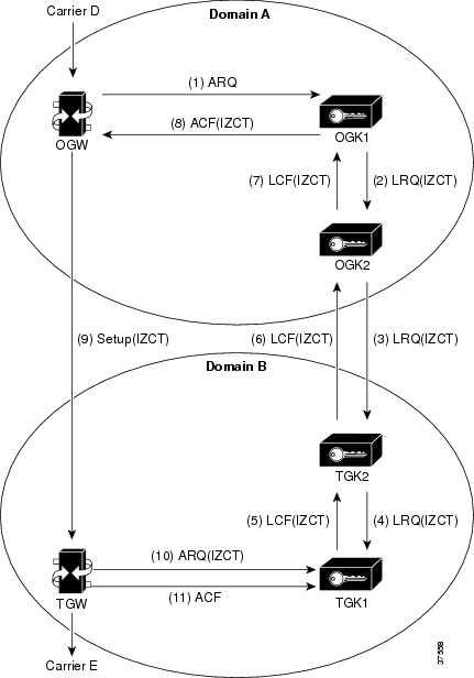
- The originating gateway sends an ARQ message with an interface description as a nonstandard field to originating gatekeeper 1 (OGK1). The interface description is treated as a source carrier identifier.
- Upon receiving the ARQ, OGK1 creates an IZCT with the following:
- srcCarrierID-- Source carrier identification, received from the ARQ
- dstCarrierID--Destination carrier identification, received from the CSR
- intCarrierID--Intermediate carrier identification, received from the CSR
- srcZone--Source zone name or a cluster name if the gatekeeper is a member of a cluster
- dstZone--Destination zone is set to null
- interZoneType--Interzone type is set to INTRA_DOMAIN_CISCO
The IZCT is sent in an LRQ to OGK2.
- OGK2 determines that the LRQ did not come from a foreign domain, replaces the IZCT's srcZoneID with its ID (or cluster name, if the gatekeeper is member of a cluster), and forwards the LRQ with the updated IZCT to terminating gatekeeper 2 (TGK2).
- TGK2 determines that the LRQ came from a foreign domain, updates the IZCT's dstZone with its own ID (or cluster name, if the gatekeeper is a member of a cluster) and the interZoneType as INTER_DOMAIN_CISCO, and passes the updated IZCT to TGK1. TGK2 treats the zone from which an LRQ is received as foreign-domain zone in either of the following two scenarios:
- TGK1 updates the IZCT's dstCarrierID to Carrier E, which is determined by the routing process; generates a hash with the IZCT's password; and sends an LCF with the updated IZCT in it. If TGK1 is a clustered gatekeeper, then the IZCT password is identical across the cluster.
- TGK2 forwards the LCF to OGK2.
- OGK2 forwards the LCF to OGK1.
- OGK1 extracts the IZCT from the LCF and sends it in an ACF to the OGW.
- The OGW sends the IZCT to the TGW in the H.225 SETUP message.
- The TGW passes the IZCT to the TGK1 in an ARQ answerCall.
- TGK1 authenticates the destination IZCT successfully, because TGK1generated the hash in the IZCT.
Note |
In the case of an inter-ITSP call, border zones (in the above example, OGK2 and TGK2) are identified as the srcZone and dstZone of the IZCT that is returned in the ACF to the OGW. If the call is intra-ITSP, leaf zones are identified as the srcZone and dstZone of the IZCT that is returned in the ACF to the OGW. |
The main tasks are marking foreign and local domain zones and setting up an IZCT password for use in all the zones. After the security izct password command is issued, the technology prefix for the gatekeepers must be configured for the gateways. The gatekeeper must be enabled to forward LRQ messages that contain E.164 addresses matching zone prefixes controlled by remote gatekeepers.
Cisco Access Tokens
The Gatekeeper-to-Gatekeeper Authentication feature provides additional security for H.323 networks by introducing the ability to validate intradomain and interdomain gatekeeper-to-gatekeeper LRQ messages on a per-hop basis. When used in conjunction with per-call security using the interzone ClearToken (IZCT), network resources are protected from attackers and security holes are prevented.
The Gatekeeper-to-Gatekeeper Authentication feature provides a Cisco access token (CAT) to carry authentication within zones. The CAT is used by adjacent gatekeepers to authenticate each other and is configured on a per-zone basis. In addition, service providers can specify inbound passwords to authenticate LRQ messages that come from foreign domains and outbound passwords to be included in LRQ messages to foreign domains.
The call flows illustrated in the figures below show the steps that occur with a successful LRQ authentication and with an unsuccessful LRQ authentication.
Note |
Although the IZCT is not required for use with the Gatekeeper-to-Gatekeeper Authentication feature, it is recommended and is shown below in the call flow examples. |
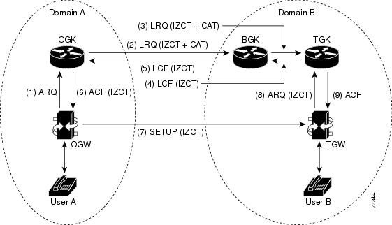
The following sequence occurs in the call flow:
- User A calls User B. The originating dial peer is configured for H.323 Registration, Admission, and Status (RAS) and sends an Admission Request (ARQ) message to the originating gatekeeper (OGK).
- Assuming the OGK has security enabled, the OGK generates an IZCT and a CAT to include in the LRQ message. The IZCT is used for per-call authorization while the CAT is used for gatekeeper-to-gatekeeper authentication. The CAT includes the following:
- general_id: gatekeeper ID (OGK)
- timeStamp: local gatekeeper time
- randomValue: a random number
- MD5 hash value
- The border gatekeeper (BGK) receives the LRQ message, checks its gatekeeper configuration, and determines that the LRQ should be authenticated before forwarding the LRQ message to the terminating gatekeeper (TGK). Once accepted, the BGK creates a new CAT and includes it in the LRQ message sent to the TGK.
- The TGK receives the LRQ message, checks its gatekeeper configuration, and determines that the LRQ should be authenticated. The E.164 address indicates that the destination is a local gateway, so the TGK acknowledges the request by sending a Location Confirmation (LCF) message, including an updated IZCT, to the BGK.
- The BGK transfers the LCF to the OGK. Normal call signaling proceeds.
- The OGK sends an Admission Confirmation (ACF) message to the OGW. The IZCT is copied to the ACF.
- The OGW sends a SETUP message to the terminating gateway (TGW).
- The TGW sends an ARQ message to the TGK. The TGK authorizes the call by comparing the IZCT with a locally created IZCT.
- The TGK sends an ACF to the TGW. The call is set up between the TGW and User B.
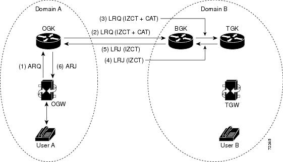
The following sequence occurs in the call flow:
- User A calls User B. The originating dial peer is configured for H.323 RAS and sends an ARQ to the OGK.
- Assuming the OGK has security enabled, the OGK generates an IZCT and a CAT to include in the LRQ message. The IZCT is used for per-call authorization while the CAT is used for gatekeeper-to-gatekeeper authentication. The CAT includes the following:
- general_id--Gatekeeper ID (OGK)
- timeStamp--Local gatekeeper time
- randomValue--A random number
- MD5 hash value
- The BGK receives the LRQ message, checks its gatekeeper configuration, and determines that the LRQ should be authenticated before forwarding the LRQ message to the TGK. Once accepted, the BGK creates a new CAT and includes it in the LRQ message sent to the TGK. However, in this example, an incorrect outbound password is used.
- The TGK receives the LRQ message, checks its gatekeeper configuration, and determines that the LRQ should be authenticated. Because an incorrect outbound password was used by the BGK, the LRQ CAT and the locally created CAT are not equivalent. The TGK sends a Location Reject (LRJ) message back to the BGK and includes a reject reason of LRJ_INVAL_PERMISSION.
- The BGK sends the LRJ to the OGK.
- The OGK sends an Admission Reject (ARJ) message to the OGW and signaling is terminated.
Tokenless Call Authorization
The Tokenless Call Authorization feature is an alternative to using IZCTs and CATs to provide gatekeeper security in an H.323 voice network. ITSPs may not control gatekeepers in other domains to which they connect; for example, if these domains do not have Cisco software installed on the gatekeepers, tokens cannot be used. Additionally, the Tokenless Call Authorization feature can be used with Cisco Call Manager; tokens cannot.
With the Tokenless Call Authorization feature, an access list of all known endpoints is configured on the gatekeeper. The gatekeeper is configured to use the access list when processing calls. Rather than rejecting all calls that do not contain IZCTs or CATs, gatekeepers reject only calls that do not have tokens and are not from endpoints on the access list.
Configuring Domain Zones and the IZCT Password
To configure domain zones and the IZCT password, use the following commands beginning in global configuration mode.
DETAILED STEPS
| Command or Action | Purpose | |
|---|---|---|
|
Step 1
|
gatekeeper
Example: Router(config)# gatekeeper |
Enters gatekeeper configuration mode. |
|
Step 2
|
security izct password password
Example: Router(config-gk)# security izct password thisismypassword |
Sets the IZCT password. The password must be from six to eight alphanumeric characters. All gatekeepers in a cluster should have the same IZCT password. To disable the IZCT password, use the no form of the command as defined in the Cisco IOS Voice Command Reference . |
|
Step 3
|
no shutdown
Example: Router(config-gk)# no shutdown |
Ensures that the gatekeepers are activated. |
|
Step 4
|
exit
Example: Router(config-gk)# exit |
Exits the current mode. |
Verifying Domain Zones and IZCT Password
DETAILED STEPS
|
show running-config
Use this command to display configuration information. Example:
Router# show running-config
gatekeeper
 zone local 35_dirgk cisco.com 172.18.198.196
 zone remote 40_gatekeeper cisco.com 172.18.198.91 1719
 zone remote 34_dirgk cisco.com 172.18.198.197 1719 foreign-domain
 zone prefix 40_gatekeeper 408*
 zone prefix 34_dirgk *
 security izct password ABCDEF
 lrq forward-queries
 no shutdown
|
Configuring Cisco Access Tokens
To configure gatekeeper-to-gatekeeper authentication, use the following commands beginning in global configuration mode.
DETAILED STEPS
| Command or Action | Purpose | |
|---|---|---|
|
Step 1
|
gatekeeper
Example: Router(config)# gatekeeper |
Enters gatekeeper configuration mode. |
|
Step 2
|
security password-group groupname lrq {receive password [encrypted] [effective hh:mm day month year] | send password [encrypted]}
Example: Router(config-gk)# security password-group groupname lrq receive password |
Defines the passwords used by remote gatekeeper zones and associates them with an ID. Keywords and arguments are as follows:
%GK-5-RX_LRQ_PASSWORD_UPDATED:LRQ receive password for security password-group 'china' has been updated.
|
|
Step 3
|
security zone {zonename | *} password-group groupname
Example: Router(config-gk)# security zone * password-group groupname |
Associates a remote zone gatekeeper with a specific password group. If a remote zone sends an LRQ message to the gatekeeper, the gatekeeper checks to see if there is a security password group configured for that remote zone name. If one exists, the gatekeeper gets the password information from the group name configured for that security zone. For example, if you used the command in Step 2 to create a password group named "china," you could use this command to associate one or more of your remote gatekeepers with that password group. Keywords and arguments are as follows:
|
|
Step 4
|
exit
Example: Router(config-gk)# exit |
Exits the current mode. |
Verifying Cisco Acess Tokens
DETAILED STEPS
|
show running-config
Use this command to verify configuration of remote zone and security features.
Example:
Router# show running-config
gatekeeper
 zone local tsunamiGK cisco 172.18.195.138
 zone remote laharGK cisco 172.18.195.139 1719
 zone prefix laharGK 987*
 security izct password 123456
 security password-group 1 lrq receive 0257550A5A57 encrypted
 security password-group 1 lrq send 144540595E56 encrypted
 security password-group 2 lrq receive 091F1D5A4A56 encrypted
 security password-group 2 lrq send 135143465F58 encrypted
 security zone larharGK password-group 1
 no shutdown
|
Configuring Tokenless Call Authorization
Configuring the IP Access List
Perform this task to create a list of endpoints known to the gatekeeper. Calls from these endpoints are accepted by the gatekeeper even if the endpoints are located in a different domain.
To configure the IP access list, use the following command beginning in global configuration mode.
DETAILED STEPS
| Command or Action | Purpose | |
|---|---|---|
|
Step 1
|
access-list access-list-number {permit | deny| remark} source [source-wildcard] [log]
Example: Router(config)# access-list 20 permit 172.16.10.190 |
Configures the access list mechanism for filtering frames by protocol type or vendor code. Keywords and arguments are as follows:
|
Configuring IP-Access-List Security on the Gatekeeper
To enable a gatekeeper to use an IP access list to perform tokenless call authorization, use the following commands beginning in global configuration mode.
DETAILED STEPS
| Command or Action | Purpose | |
|---|---|---|
|
Step 1
|
gatekeeper
Example: Router(config)# gatekeeper |
Enters gatekeeper configuration mode. |
|
Step 2
|
security acl answerarq access-list-number
Example: Router(config-gk)# security acl answerarq 20 |
Instructs the gatekeeper to use an IP access list--also known as an access control list (ACL)--to verify calls. Calls received from endpoints listed in the ACL are processed by the gatekeeper regardless of whether they contain IZCTs or CATs in the ARQ message from the endpoint. Rather than sending a Location Reject (LRJ) message for calls without tokens from these endpoints, the gatekeeper sends an admission confirm (ACF) message and accepts the calls. |
|
Step 3
|
exit
Example: Router(config-gk)# exit |
Exits the current mode. |
Configuring E.164 Interzone Routing
This section contains the following information:
Information About E.164 Interzone Routing
You can configure interzone routing using E.164 addresses.
Two types of address destinations are used in H.323 calls. You can specify a destination using either an H.323-ID address (a character string) or an E.164 address (a string that contains telephone keypad characters). The way in which interzone calls are routed depends on the type of address being used.
When using H.323-ID addresses, interzone routing is handled through the use of domain names. For example, to resolve the domain name bob@cisco.com, the source endpoint gatekeeper finds the gatekeeper for cisco.com and sends it the location request for the target address bob@cisco.com. The destination gatekeeper looks in its registration database, sees bob registered, and returns the appropriate IP address to get to bob.
When using E.164 addresses, call routing is handled through zone prefixes and gateway-type prefixes, also referred to as technology prefixes. The zone prefixes, which are typically area codes, serve the same purpose as domain names in H.323-ID address routing. Unlike domain names, however, more than one zone prefix can be assigned to one gatekeeper, but the same prefix cannot be shared by more than one gatekeeper.
Use the zone prefix command to define gatekeeper responsibilities for area codes. The command can also be used to tell the gatekeeper which prefixes are in its own zones and which remote gatekeepers are responsible for other prefixes.
Note |
Area codes are used as an example in this section, but a zone prefix need not be an area code. It can be a country code, an area code plus local exchange (NPA-NXX), or any other logical hierarchical partition. |
The following sample command shows how to configure a gatekeeper with the knowledge that zone prefix 212....... (that is, any address beginning with area code 212 and followed by seven arbitrary digits) is handled by gatekeeper gk-ny:
my-gatekeeper(config-gk)# zone prefix gk-ny 212.......
When my-gatekeeper is asked to admit a call to destination address 2125551111, it knows to send the location request to gk-ny.
However, once the query gets to gk-ny, gk-ny still needs to resolve the address so that the call can be sent to its final destination. There could be an H.323 endpoint that has registered with gk-ny with that E.164 address, in which case gk-ny would return the IP address for that endpoint. However, it is more likely that the E.164 address belongs to a non-H.323 device, such as a telephone or an H.320 terminal.
Because non-H.323 devices do not register with gatekeepers, gk-ny has no knowledge of which device the address belongs to or which type of device it is, so the gatekeeper cannot decide which gateway should be used for the hop off to the non-H.323 device. (The term hop off refers to the point at which the call leaves the H.323 network and is destined for a non-H.323 device.)
Note |
The number of zone prefixes defined for a directory gatekeeper that is dedicated to forwarding LRQs, and not for handling local registrations and calls, should not exceed 10,000; 4 MB of memory must be dedicated to describing zones and zone prefixes to support this maximum number of zone prefixes. The number of zone prefixes defined for a gatekeeper that handles local registrations and calls should not exceed 2000. |
To enable the gatekeeper to select the appropriate hop-off gateway, use the gw-type-prefix command to configure technology or gateway-type prefixes. Select technology prefixes to denote different types or classes of gateways. The gateways are then configured to register with their gatekeepers using these technology prefixes.
For example, voice gateways might register with technology prefix 1#, and H.320 gateways might register with technology prefix 2#. If there are several gateways of the same type, configure them to register with the same prefix type. By having them register with the same prefix type, the gatekeeper treats the gateways as a pool out of which a random selection is made whenever a call for that prefix type arrives. If a gateway can serve more than one type of hop-off technology, it can register more than one prefix type with the gatekeeper.
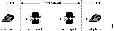
Callers must identify the type of gateway by prepending the appropriate technology prefix for that gateway type to the destination address. For example, callers might request 1#2125551111 if they know that address 2125551111 is for a telephone and that the technology prefix for voice gateways is 1#. The voice gateway is configured with a dial peer (using the dial-peer command) so that when the gateway receives the call for 1#2125551111, it strips off the technology prefix 1# and bridges the next leg of the call to the telephone at 2125551111.
In cases in which the call scenario is as shown in the figure below, voice-gw1 can be configured to prepend the voice technology prefix 1# so that the use of technology prefixes is completely transparent to the caller.
Additionally, in using the gw-type-prefix command, a particular gateway-type prefix can be defined as the default gateway type to be used for addresses that cannot be resolved. It also forces a technology prefix to always hop off in a particular zone.
If the majority of calls hop off on a particular type of gateway, the gatekeeper can be configured to use that type of gateway as the default type so that callers no longer have to prepend a technology prefix on the address. For example, if voice gateways are mostly used in a network, and all voice gateways have been configured to register with technology prefix 1#, the gatekeeper can be configured to use 1# gateways as the default technology if the following command is entered:
Router(config-gk)# gw-type-prefix 1# default-technology
Now a caller no longer needs to prepend 1# to use a voice gateway. Any address that does not contain an explicit technology prefix is routed to one of the voice gateways that registered with 1#.
With this default technology definition, a caller could ask the gatekeeper for admission to 2125551111. If the local gatekeeper does not recognize the zone prefix as belonging to any remote zone, it routes the call to one of its local (1#) voice gateways so that the call hops off locally. However, if it knows that gk-ny handles the 212 area code, it can send a location request for 2125551111 to gk-ny. This requires that gk-ny also be configured with some default gateway type prefix and that its voice gateways be registered with that prefix type.
Note |
For ease of maintenance, the same prefix type should be used to denote the same gateway type in all zones under your administration. |
Also, with the gw-type-prefix command, a hop off can be forced to a particular zone. When an endpoint or gateway makes a call-admission request to its gatekeeper, the gatekeeper determines the destination address by first looking for the technology prefix. When that is matched, the remaining string is compared against known zone prefixes. If the address is determined to be a remote zone, the entire address, including technology and zone prefixes, is sent to the remote gatekeeper in a location request. That remote gatekeeper then uses the technology prefix to decide on which of its gateways to hop off. In other words, the zone prefix (defined using the zone prefix command) determines the routing to a zone, and once there, the technology prefix (defined using the gw-type-prefix command) determines the gateway to be used in that zone. The zone prefix takes precedence over the technology prefix.
This behavior can be overridden by associating a forced hop-off zone with a particular technology prefix. Associating a forced hop-off zone with a particular technology prefix forces the call to the specified zone, regardless of what the zone prefix in the address is. As an example, you are in the 408 area code and want callers to the 212 area code in New York to use H.323-over-IP and hop off there because it saves on costs. However, the only H.320 gateway is in Denver. In this example, calls to H.320 endpoints must be forced to hop off in Denver, even if the destination H.320 endpoint is in the 212 area code. The forced hop-off zone can be either a local zone (that is, one that is managed by the local gatekeeper) or a remote zone.
Configuring a Dialing Prefix for Each Gateway
To configure a dialing prefix for each gateway, use the following commands beginning in global configuration mode.
DETAILED STEPS
| Command or Action | Purpose | |
|---|---|---|
|
Step 1
|
gatekeeper
Example: Router(config)# gatekeeper |
Enters gatekeeper configuration mode. |
|
Step 2
|
zone local gatekeeper-name domain-name [ ras-ip-address ]
Example: Router(config-gk)# zone local gatekeeper1 domain1 |
Specifies a zone controlled by a gatekeeper. |
|
Step 3
|
zone prefix gatekeeper-name e164-prefix [ gw-priority pri-0-to-10 gw-alias [ gw-alias, ... ]]
Example: Router(config-gk)# zone prefix localgk 415....... gw-priority 10 gw1 gw2 |
Adds a prefix to the gatekeeper zone list. To remove knowledge of a zone prefix, use the no form of this command with the gatekeeper name and prefix. To remove the priority assignment for a specific gateway, use the no form of this command with the gw-priority keyword. To put all of your gateways in the same zone, use the gw-priority keyword as described below. |
|
Step 4
|
exit
Example: Router(config-gk)# exit |
Exits the current mode. |
To put all of your gateways in the same zone, use the gw-priority keyword and specify which gateways are used for calling different area codes. For example:
          zone local localgk xyz.com

          zone prefix localgk 408.......

          zone prefix localgk 415....... gw-priority 10 gw1 gw2

          zone prefix localgk 650....... gw-priority 0 gw1
The above commands accomplish the following:
- Domain xyz.com is assigned to gatekeeper localgk.
- Prefix 408 is assigned to gatekeeper localgk, and no gateway priorities are defined for it; therefore, all gateways registering to localgk can be used equally for calls to the 408 area code. No special gateway lists are built for the 408 prefix; a selection is made from the master list for the zone.
- The prefix 415 is added to gatekeeper localgk, and priority 10 is assigned to gateways gw1 and gw2.
- Prefix 650 is added to gatekeeper localgk, and priority 0 is assigned to gateway gw1.
- A priority 0 is assigned to gateway gw1 to exclude it from the gateway pool for prefix 650. When gw2 registers with gatekeeper localgk, it is added to the gateway pool for each prefix as follows:
- For gateway pool for 415, gateway gw2 is set to priority 10.
- For gateway pool for 650, gateway gw2 is set to priority 5.
Configuring Gatekeeper Interaction with External Applications
There are two ways of configuring the gatekeeper for interaction with an external application. You can configure a port number where the gatekeeper listens for dynamic registrations from applications. Using this method, the application connects to the gatekeeper and specifies the trigger conditions in which it is interested.
The second method involves using the command-line interface to statically configure the information about the application and its trigger conditions, in which case the gatekeeper initiates a connection to the external application.
Cisco provides a Gatekeeper Transaction Message Protocol (GKTMP) server and commands to configure the gatekeeper to communicate with the server using GKTMP messages.
Note |
For configuration information, see VoIP Gatekeeper Trunk and Carrier Based Routing Enhancements at http://www.cisco.com/en/US/docs/ios/12_2t/12_2t11/feature/guide/ftgkrenb.html |
This section contains the following information:
- Configuring Gatekeeper-to-GKTMP Server Flow Control
- Verifying Gatekeeper-to-GKTMP Server Flow Control
- Setting the Retry Timer for Failed GKTMP Server Connections
- Verifying the Retry Timer for Failed GKTMP Server Connections
- Configuring Registration and Call Rejection
- Verifying Registration and Call Rejection
Configuring Gatekeeper-to-GKTMP Server Flow Control
You can set a timeout value for responses from the GKTMP server to the gatekeeper. Thegatekeeper measures the average time taken by the server to process each transaction. If the time period for processing reaches 80 percent of the configured timeout value, the server is marked as unavailable. Thegatekeeper routes transactions bound for this server to alternate servers if they are available. If no alternate servers are available, thegatekeeper handles the calls.
To configure server flow control, use the following commands beginning in global configuration mode.
DETAILED STEPS
| Command or Action | Purpose | |
|---|---|---|
|
Step 1
|
gatekeeper
Example: Router(config)# gatekeeper |
Enters gatekeeper configuration mode. |
|
Step 2
|
server flow-control [onset value] [abatement value] [qcount value]
Example: Router(config-gk)# server flow-control onset 50 abatement 25 qcount 100 |
Enables flow control and resets all the thresholds to default. Keywords and arguments are as follows:
For example, if the server timeout value is 3 seconds, onsetvalue is 50, and abatementvalue is 40, when the average response time from the server to the GKTMP reaches 1.5 seconds (the onset percentage of the server timeout value), the server is marked as unusable. During the period that the server is marked as unusable, REQUEST ALV messages are still sent to the unusable server. When the response time is lowered to 1.2 seconds (the abatement percentage of the timeout value), the server is marked usable again and the GKTMP resumes sending messages to the server.
|
|
Step 3
|
exit
Example: Router(config-gk)# exit |
Exits the current mode. |
Verifying Gatekeeper-to-GKTMP Server Flow Control
DETAILED STEPS
| Step 1 | show running-config Use this command to verify that server flow-control appears in the output. Example:
Router# show running-config
Building configuration...
Current configuration : 1055 bytes
!
version 12.2
no service single-slot-reload-enable
service timestamps debug datetime msec
service timestamps log uptime
no service password-encryption
!
hostname snet-3660-3
!
.
.
.
gatekeeper
 zone local snet-3660-3 cisco.com
 zone remote snet-3660-2 cisco.com 209.165.200.225 1719
 zone prefix snet-3660-2 408*
 lrq forward-queries
 no use-proxy snet-3660-3 default inbound-to terminal
 no use-proxy snet-3660-3 default outbound-from terminal
 no shutdown
 server registration-port 8000
 server flow-control
!
.
.
.
|
| Step 2 | show gatekeeper status Use this command to view the status of the GKTMP Interface Resiliency Enhancement feature. The following example shows that the GKTMP Interface Resiliency Enhancement feature is enabled: Example:
Router# show gatekeeper status
Gatekeeper State: UP
    Load Balancing:   DISABLED
    Flow Control:     ENABLED
    Zone Name:        snet-3660-3
    Accounting:       DISABLED
    Endpoint Throttling:        DISABLED
    Security:         DISABLED
    Maximum Remote Bandwidth:              unlimited
    Current Remote Bandwidth:              0 kbps
    Current Remote Bandwidth (w/ Alt GKs): 0 kbps
|
| Step 3 | show gatekeeper servers Use this command to view the server statistics, including timeout encountered, average response time, and server status. Example:
Router# show gatekeeper servers
            GATEKEEPER SERVERS STATUS
            =========================
Gatekeeper Server listening port: 8250
Gatekeeper Server timeout value: 30 (100ms)
GateKeeper GKTMP version: 3.1
Gatekeeper-ID: Gatekeeper1
------------------------
  RRQ  Priority: 5
    Server-ID: Server43
    Server IP address: 209.165.200.254:40118
    Server type: dynamically registered
    Connection Status: active
    Trigger Information:
      Trigger unconditionally
    Server Statistics:
    REQUEST RRQ Sent=0
    RESPONSE RRQ Received = 0
    RESPONSE RCF Received = 0
    RESPONSE RRJ Received = 0
    Timeout encountered=0
    Average response time(ms)=0
    Server Usable=TRUE
|
Setting the Retry Timer for Failed GKTMP Server Connections
To configure faster reconnection to a GKTMP server when its TCP connection fails, use the following commands beginning in global configuration mode.
DETAILED STEPS
| Command or Action | Purpose | |||
|---|---|---|---|---|
|
Step 1
|
gatekeeper
Example: Router(config)# gatekeeper |
Enters gatekeeper configuration mode. |
||
|
Step 2
|
timer server retry seconds
Example: Router(config-gk)# timer server retry 20 |
Sets the retry timer for failed GKTMP server connections, in seconds. After the gatekeeper detects that its GKTMP server TCP connection has failed, the gatekeeper retries the server based on the setting of this timer, and keep retrying until the connection is established. Range: 1 to 300. Default: 30.
|
||
|
Step 3
|
exit
Example: Router(config-gk)# exit |
Exits the current mode. |
Verifying the Retry Timer for Failed GKTMP Server Connections
DETAILED STEPS
|
show gatekeeper servers
Use this command to verify the retry timer for failed server connections. Example:
Router# show gatekeeper servers
            GATEKEEPER SERVERS STATUS
            =========================
Gatekeeper Server listening port:0
Gatekeeper Server response timeout value:30 (100ms)
Gatekeeper Server connection retry timer value:30 (sec)
Gatekeeper GKTMP version:4.1
|
Configuring Registration and Call Rejection
To configure the gatekeeper to reject new registrations or calls when it is unable to reach the GKTMP server because the TCP connection between the gatekeeper and GKTMP server is down, use these commands beginning in global configuration mode.
DETAILED STEPS
| Command or Action | Purpose | |||
|---|---|---|---|---|
|
Step 1
|
gatekeeper
Example: Router(config)# gatekeeper |
Enters gatekeeper configuration mode. |
||
|
Step 2
|
server absent reject {rrq | arq}
Example: Router(config-gk)# server absent reject rrq |
Configures the gatekeeper to reject new registrations or calls when it is unable to reach the GKTMP server because the TCP connection between gatekeeper and server is down. If multiple GKTMP servers are configured, the gatekeeper tries all of them and rejects registrations or calls only if none of the servers responds. Keywords are as follows:
You can also use this feature for security or service denial if a connection with the server is required to complete a registration. Default: this feature is not enabled; the gatekeeper does not reject new registrations or calls.
|
||
|
Step 3
|
exit
Example: Router(config-gk)# exit |
Exits the current mode. |
Verifying Registration and Call Rejection
DETAILED STEPS
|
show running-config
Use this command to verify that the gatekeeper is rejecting new registrations when unable to reach the GKTMP server. Example:
Router# show running-config
.
.
.
gw-type-prefix 1#* default-technology
gw-type-prefix 9#* gw ipaddr 1.1.1.1 1720
no shutdown
server absent reject rrq
.
.
.
Use this command to verify that the gatekeeper is rejecting new calls when unable to reach the GKTMP server, use the command. Example:
Router# show running-config
.
.
.
gw-type-prefix 1#* default-technology
gw-type-prefix 9#* gw ipaddr 1.1.1.1 1720
no shutdown
server absent reject arq
.
.
.
|
Configuring Gatekeeper Proxied Access
By default, a gatekeeper offers the IP address of the local proxy when queried by a remote gatekeeper (synonymous with remote zone) or the border element. This is considered proxied access.
Note |
The use-proxy command replaces the zone access command. The use-proxy command, configured on a local gatekeeper, affects only the use of proxies for incoming calls (that is, it does not affect the use of local proxies for outbound calls). When originating a call, a gatekeeper uses a proxy only if the remote gatekeeper offers a proxy at the remote end. A call between two endpoints in the same zone is always a direct (nonproxied) call. |
To configure a proxy for inbound calls from remote zones or the border element to gateways in its local zone and to configure a proxy for outbound calls from gateways in its local zone to remote zones or the border element, use the following commands beginning in global configuration mode.
DETAILED STEPS
| Command or Action | Purpose | |
|---|---|---|
|
Step 1
|
gatekeeper
Example: Router(config)# gatekeeper |
Enters gatekeeper configuration mode. |
|
Step 2
|
use-proxy local-zone-name { default | h323-annexg | remote-zone remote-zone-name } { inbound-to | outbound-from } { gateway | terminal }
Example: Router(config-gk)# use-proxy zonename default inbound-to gateway |
Enables proxy communications for calls between local and remote zones. Keywords and arguments are as follows:
|
|
Step 3
|
exit
Example: Router(config-gk)# exit |
Exits the current mode. |
Verifying Gatekeeper Proxied Access
DETAILED STEPS
|
show gatekeeper zone status
Use this command to see information about the configured gatekeeper proxies and gatekeeper zone information (as shown in the following output). Example:
Router# show gatekeeper zone status
                      GATEKEEPER ZONES
                      ================
GK name      Domain Name   RAS Address     PORT  FLAGS MAX-BW   CUR-BW
                                                       (kbps)   (kbps)
-------      -----------   -----------     ----  ----- ------   ------
sj.xyz.com   xyz.com       10.0.0.9 1719  LS             0
  SUBNET ATTRIBUTES :
    All Other Subnets :(Enabled)
  PROXY USAGE CONFIGURATION :
    inbound calls from germany.xyz.com :
      to terminals in local zone sj.xyz.com :use proxy
      to gateways in local zone sj.xyz.com  :do not use proxy
    outbound calls to germany.xyz.com
      from terminals in local zone germany.xyz.com :use proxy
      from gateways in local zone germany.xyz.com  :do not use proxy
    inbound calls from H.225 AnnexG border element :
      to terminals in local zone germany.xyz.com :use proxy
      to gateways in local zone germany.xyz.com  :do not use proxy
    outbound calls to H.225 AnnexG border element :
      from terminals in local zone germany.xyz.com :use proxy
      from gateways in local zone germany.xyz.com  :do not use proxy
    inbound calls from all other zones :
      to terminals in local zone sj.xyz.com :use proxy
      to gateways in local zone sj.xyz.com  :do not use proxy
    outbound calls to all other zones :
      from terminals in local zone sj.xyz.com :do not use proxy
      from gateways in local zone sj.xyz.com  :do not use proxy
tokyo.xyz.co xyz.com       172.21.139.89      1719  RS             0
milan.xyz.co xyz.com       172.16.00.00       1719  RS             0
|
Configuring a Forced Disconnect on a Gatekeeper
DETAILED STEPS
| Command or Action | Purpose | |
|---|---|---|
|
Step 1
|
clear h323 gatekeeper call {all | local-callID local-call-id}
Example: Router# clear h323 gatekeeper call all |
Forces a disconnect on a specific call or on all calls currently active on this gatekeeper. Keywords and arguments are as follows:
|
Note |
To force a particular call to disconnect (as opposed to all active calls on the H.323 gateway), use the local call identification number (CallID) to identify that specific call. Find the local CallID number for a specific call by using the show gatekeeper callscommand; the ID number is displayed in the LocalCallID column. |
Verifying a Forced Disconnect on a Gatekeeper
DETAILED STEPS
|
show gatekeeper calls
Use this command to show the status of each ongoing call that a gatekeeper is aware of. If you have forced a disconnect either for a particular call or for all calls associated with a particular H.323 gatekeeper, the system does not display information about those calls. Example:
router# show gatekeeper calls
Total number of active calls =1
                    Gatekeeper Call Info
                    ====================
LocalCallID                    Age (secs)      BW
12-3339                        94              768 (Kbps)
 Endpt(s): Alias    E.164Addr   CallSignalAddr   Port   RASSignalAddr   Port
  src EP: epA                    10.0.0.11        1720   10.0.0.11        1700
  dst EP: epB2zoneB.com
  src PX: pxA                    10.0.0.1         1720   10.0.0.11        24999
  dst PX: pxB                    172.21.139.90    1720   172.21.139.90    24999
|
Configuring an H.323 Proxy Server
The following sections describes how the proxy feature can be used in an H.323 network.
When terminals signal each other directly, they must have direct access to each other's addresses. This exposes an attacker to key information about a network. When a proxy is used, the only addressing information that is exposed to the network is the address of the proxy; all other terminal and gateway addresses are hidden.
There are several ways to use a proxy with a firewall to enhance network security. The configuration to be used depends on how capable the firewall is of handling the complex H.323 protocol suite. Each of the following sections describes a common configuration for using a proxy with a firewall:
Proxy Inside the Firewall
H.323 is a complex, dynamic protocol that consists of several interrelated subprotocols. During H.323 call setup, the ports and addresses released with this protocol require a detailed inspection as the setup progresses. If the firewall does not support this dynamic access control based on the inspection, a proxy can be used just inside the firewall. The proxy provides a simple access control scheme, as illustrated in the figure below.
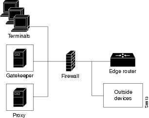
Because the gatekeeper (using RAS) and the proxy (using call setup protocols) are the only endpoints that communicate with other devices outside the firewall, it is simple to set up a tunnel through the firewall to allow traffic destined for either of these two endpoints to pass through.
Proxy in Co-Edge Mode
If H.323 terminals exist in an area with local interior addresses that must be translated to valid exterior addresses, the firewall must be capable of decoding and translating all addresses passed in the various H.323 protocols. If the firewall is not capable of this translation task, a proxy may be placed next to the firewall in a co-edge mode. In this configuration, interfaces lead to both inside and outside networks. (See the figure below.)
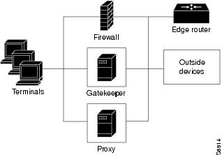
In co-edge mode, the proxy can present a security risk. To avoid exposing a network to unsolicited traffic, configure the proxy to route only proxied traffic. In other words, the proxy routes only H.323 protocol traffic that is terminated on the inside and then repeated to the outside. Traffic that moves in the opposite direction can be configured this way as well.
Proxy Outside the Firewall
To place the proxy and gatekeeper outside the firewall, two conditions must exist. First, the firewall must support H.323 dynamic access control. Second, Network Address Translation (NAT) must not be in use.
If NAT is in use, each endpoint must register with the gatekeeper for the duration of the time it is online. This quickly overwhelms the firewall because a large number of relatively static, internal-to-external address mappings need to be maintained.
If the firewall does not support H.323 dynamic access control, the firewall can be configured with static access lists that allow traffic from the proxy or gatekeeper through the firewall. This can present a security risk if an attacker can spoof, or simulate, the IP addresses of the gatekeeper or proxy and use them to attack the network. The figure below illustrates proxy outside the firewall.
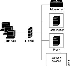
Proxy and NAT
When a firewall is providing NAT between an internal and an external network, proxies may allow H.323 traffic to be handled properly, even in the absence of a firewall that can translate addresses for H.323 traffic. The tables below provide guidelines for proxy deployment for networks that use NAT.
| Table 2 | Guidelines for Networks That Use NAT |
| For Networks Using NAT |
Firewall with H.323 NAT |
Firewall Without H.323 NAT |
|---|---|---|
| Firewall with dynamic access control |
Gatekeeper and proxy inside the firewall |
Co-edge gatekeeper and proxy |
| Firewall without dynamic access control |
Gatekeeper and proxy inside the firewall, with static access lists on the firewall |
Co-edge gatekeeper and proxy |
| Table 3 | Guidelines for Networks That Do Not Use NAT |
| For Networks Not Using NAT |
Firewall with H.323. NAT |
Firewall Without H.323 NAT |
|---|---|---|
| Firewall with Dynamic Access Control |
Gatekeeper and proxy inside the firewall Gatekeeper and proxy outside the firewall |
Gatekeeper and proxy inside the firewall Gatekeeper and proxy outside the firewall |
| Firewall Without Dynamic Access Control |
Gatekeeper and proxy inside the firewall, with static access lists on the firewall |
Gatekeeper and proxy inside the firewall, with static access lists on the firewall |
Configuring Quality of Service
This section contains the following information:
- Prerequisites for QoS
- Information About QoS
- Configuring QoS Using a Multimedia Backbone
- Configuring QoS on a Proxy Without ASR
- Configuring QoS on a Proxy with ASR
- ASR Enabled on the Proxy Using One Type of Routing Protocol
- ASR Enabled on the Proxy Using Two Different Autonomous Systems
Prerequisites for QoS
- The proxy is not capable of modifying the Quality of Service (QoS) between the terminal and itself. To achieve the best overall QoS, ensure that terminals are connected to the proxy using a network that intrinsically has good QoS. In other words, configure a path between a terminal and proxy that provides good bandwidth, delay, and packet-loss characteristics without the terminal needing to request special QoS. A high-bandwidth LAN works well for this.
Information About QoS
QoS enables complex networks to control and predictably service a variety of applications. QoS expedites the handling of mission-critical applications while sharing network resources with noncritical applications. QoS also ensures available bandwidth and minimum delays required by time-sensitive multimedia and voice applications. In addition, QoS gives network managers control over network applications, improves cost-efficiency of WAN connections, and enables advanced differentiated services. QoS technologies are elemental building blocks for other Cisco IOS-enabling services such as its H.323-compliant gatekeeper. Overall call quality can be improved dramatically in the multimedia network by using pairs of proxies between regions of the network where QoS can be requested.
RSVP and IP Precedence
When two H.323 terminals communicate directly, the resulting call quality can range from good (for high-bandwidth intranets) to poor (for most calls over the public network). As a result, deployment of H.323 is almost always predicated on the availability of some high-bandwidth, low-delay, low-packet-loss network that is separate from the public network or that runs overlaid with the network as a premium service and adequate QoS.
Adequate QoS usually requires terminals that are capable of signaling such premium services. There are two major ways to achieve such signaling:
- Resource Reservation Protocol (RSVP) to reserve flows having adequate QoS based on the media codecs of H.323 traffic
- IP precedence bits to signal that the H.323 traffic is special and that it deserves higher priority
Unfortunately, the vast majority of H.323 terminals cannot achieve signaling in either of these ways. The proxy can be configured to use any combination of RSVP and IP precedence bits.
Note |
For more information on RSVP, synchronous reservation timers, and slow connect, see Quality of Service for Voice at http://www.cisco.com/en/US/docs/ios/qos/configuration/guide/15_0/qos_15_0_book.html |
Application-Specific Routing
To achieve adequate QoS, a separate network may be deployed that is partitioned away from the standard data network. The proxy can take advantage of such a partitioned network using a feature known as application-specific routing (ASR).
Application-specific routing is simple. When the proxy receives outbound traffic, it directs traffic to an interface that is connected directly to the QoS network. The proxy does not send the traffic using an interface that is specified for the regular routing protocol. Similarly, inbound traffic from other proxies is received on the interface that is connected to the QoS network. This is true if all these other proxies around the QoS network use ASR in a consistent fashion. ASR then ensures that ordinary traffic is not routed into the QoS network by mistake.
Implementation of ASR ensures the following:
- Each time a connection is established with another proxy, the proxy automatically installs a host route pointing at the interface designated for ASR.
- The proxy is configured to use a loopback interface address. The proxy address is visible to both the ASR interface and all regular interfaces, but there are no routes established between the loopback interface and the ASR interface. This ensures that no non-H.323 traffic is routed through the ASR interface.
Note |
ASR is not supported on Frame Relay or ATM interfaces for the Cisco MC3810. |
Configuring QoS Using a Multimedia Backbone
The examples in this section illustrate a separate multimedia backbone network dedicated to transporting only H.323 traffic. The closed functionality of the H.323 proxy is necessary for creating this type of backbone. Place a closed H.323 proxy on each edge of the multimedia backbone to achieve the following goals:
- The proxy directs all inter-proxy H.323 traffic, including Q.931 signaling, H.245, and media stream, to the multimedia backbone.
- The proxy shields the multimedia backbone so that routers on edge networks and other backbone networks are not aware of its existence. In this way, only H.323-compliant packets can access or traverse the multimedia backbone.
- The proxy drops any unintended non-H.323 packets that attempt to access the multimedia backbone.
The figure below illustrates a network that has a multimedia backbone. A gatekeeper (not shown) in the edge network (zone) directs all out-of-zone H.323 calls to the closed proxy on the edge of that network. The closed proxy forwards this traffic to the remote zone through the multimedia backbone. A closed proxy and the edge router may reside in the same router or they may be in separate routers, as shown in the figure.
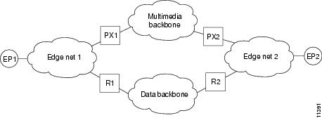
Enabling the Proxy to Forward H.323 Packets
To enable the proxy to forward H.323 packets received from the edge network to the multimedia backbone, designate the interface that connects the proxy to the multimedia backbone to the ASR interface by entering the h323 asr command in interface configuration mode. Enabling the proxy to forward H.323 packets satisfies the first goal identified earlier in this section.
Because the proxy terminates two call legs of an H.323 call and bridges them, any H.323 packet that traverses the proxy has the proxy address either in its source field or in its destination field.
To prevent problems that can occur in proxies that have multiple IP addresses, designate only one interface to be the proxy interface by entering the h323 interface command in interface configuration mode. Then all H.323 packets that originate from the proxy has the address of this interface in their source fields, and all packets that are destined to the proxy has the address of this interface in their destination fields.
Enabling the Proxy to Forward H.323 Packets illustrates that all physical proxy interfaces belong either to the multimedia network or to the edge network. These two networks must be isolated from each other for the proxy to be closed; however, the proxy interface must be addressable from both the edge network and the multimedia network. For this reason, a loopback interface must be created on the proxy and configured to the proxy interface.
It is possible to make the loopback interface addressable from both the edge network and the multimedia network without exposing any physical subnets on one network to routers on the other network. Only packets that originate from the proxy or packets that are destined to the proxy can pass through the proxy interface to the multimedia backbone in either direction. All other packets are considered unintended packets and are dropped. This can be achieved by configuring access control lists (ACLs) so that the closed proxy acts like a firewall that only allows H.323 packets to pass through the ASR interface. This satisfies the second goal identified earlier in this section, which is to ensure that only H.323-compliant packets can access or traverse the multimedia backbone.
Isolating the Multimedia Network
The last step is to configure the network so that non-H.323 traffic never attempts to traverse the multimedia backbone and so that it never risks being dropped by the proxy. This is achieved by completely isolating the multimedia network from all edge networks and from the data backbone and by configuring routing protocols on the various components of the networks.
The example provided in Isolating the Multimedia Network requires availability of six IP address classes, one for each of the four autonomous systems and one for each of the two loopback interfaces. Any Cisco-supported routing protocol can be used on any of the autonomous systems, with one exception: Routing Information Protocol (RIP) cannot be configured on two adjacent autonomous systems because this protocol does not include the concept of an autonomous system. The result would be the merging of the two autonomous systems into one.
If the number of IP addresses are scarce, use subnetting, but the configuration can get complicated. In this case, only the Enhanced IGRP, Open Shortest Path First (OSPF), and RIP Version 2 routing protocols, which allow variable-length subnet masks (VLSMs), can be used.
Assuming these requirements are met, configure the network illustrated in Isolating the Multimedia Network as follows:
- Configure each of the four networks as a separate routing autonomous system and do not redistribute routes between the multimedia backbone and any other autonomous system.
- Create a loopback interface on the proxy and configure it to be the proxy interface. That way no subnets of the multimedia backbone are exposed to the edge network, or the other way around.
- To ensure that the address of the loopback interface does not travel outside the edge network, configure the appropriate distribution list on the edge router that connects the edge network to the data backbone. Configuring the appropriate distribution list guarantees that any ongoing H.323 call is interrupted if the multimedia backbone fails. Otherwise, H.323 packets that originate from one proxy and that are destined to another proxy might discover an alternate route using the edge networks and the data backbone.
In some topologies, the two edge networks and the data backbone may be configured as a single autonomous system, but it is preferable to separate them as previously described because they are different networks with different characteristics.
Configuring QoS on a Proxy Without ASR
To start the proxy without application-specific routing (ASR), start the proxy and then define the H.323 name, zone, and QoS parameters on the interface whose IP address the proxy uses. To start the proxy without ASR, use the following commands beginning in global configuration mode.
DETAILED STEPS
| Command or Action | Purpose | |
|---|---|---|
|
Step 1
|
proxy h323
Example: Router(config)# proxy h323 |
Starts the proxy. |
|
Step 2
|
interface type number [nametag]
Example: Router(config)# interface serial 0 |
Enters interface configuration mode for a particular interface or subinterface. Keywords and arguments are platform dependent; for more information, see the IOS interface command reference listed in the Additional References. |
|
Step 3
|
h323 interface [ port ]
Example: Router(config-if)# h323 interface 1 |
Selects an interface whose IP address is used by the proxy to register with the gatekeeper. The argument are as follows: |
|
Step 4
|
h323 h323-id h323-id
Example: Router(config-if)# h323 h323-id PX1@zone1.com |
Configures the proxy name. (More than one name may be configured if necessary.) The argument is as follows:
|
|
Step 5
|
h323 gatekeeper [ id gatekeeper-id ] { ipaddr ip-address [ port ] | multicast }
Example: Router(config-if)# h323 gatekeeper ipaddr 10.0.0.0 |
Specifies the gatekeeper associated with a proxy and controls how the gatekeeper is discovered. Keywords and arguments are as follows:
|
|
Step 6
|
h323 qos {ip-precedence | rsvp {controlled-load | guaranteed-qos}}
Example: Router(config-if)# h323 qos rsvp guaranteed-qos |
Enables QoS on the proxy. Keywords and arguments are as follows:
|
|
Step 7
|
ip route-cache [ cbus ] same-interface [ flow ] distributed
Example: Router(config-if)# ip route-cache same-interface distributed |
Controls the use of high-speed switching caches for IP routing. Keywords are as follows:
|
|
Step 8
|
exit
Example: Router(config-if)# exit |
Exits the current mode. |
Configuring QoS on a Proxy with ASR
To enable ASR on the proxy, start the proxy and then define the H.323 name, zone, and QoS parameters on the loopback interface. Next, determine which interface is used to route the H.323 traffic and configure ASR on it. The ASR interface and all other interfaces must be separated so that routing information never travels from one to the other. There are two different ways to separate the ASR interface and all other interfaces:
- Use one type of routing protocol on the ASR interface and another on all the non-ASR interfaces. Include the loopback subnet in both routing domains.
- Set up two different autonomous systems, one that contains the ASR network and the loopback network and another that contains the other non-ASR networks and loopback network.
To ensure that the ASR interface and all other interfaces never route packets between each other, configure an access control list. (The proxy traffic is routed specially because it is always addressed to the loopback interface first and then translated by the proxy subsystem.)
Note |
ASR is not supported on Frame Relay or ATM interfaces for the Cisco MC3810. |
ASR Enabled on the Proxy Using One Type of Routing Protocol
To start the proxy with ASR enabled on the proxy using one type of routing protocol on the ASR interface and another on all of the non-ASR interfaces, and with the loopback subnet included in both routing domains, use the following commands beginning in global configuration mode.
DETAILED STEPS
| Command or Action | Purpose | |
|---|---|---|
|
Step 1
|
proxy h323
Example: Router(config)# proxy h323 |
Starts the proxy. |
|
Step 2
|
interface type number [ nametag ]
Example: Router(config)# interface loopback 3 |
Enters loopback-interface configuration mode. Keywords and arguments are platform dependent; for more information, see the IOS interface command reference listed in the Additional References. To configure a proxy with ASR enabled on the proxy using one type of routing protocol, set type to loopback. The loopback type specifies the software-only loopback interface that emulates an interface that is always up. It is a virtual interface supported on all platforms. The number argument is the number of the loopback interface that you want to create or configure. There is no limit on the number of loopback interfaces that you can create. |
|
Step 3
|
ip address ip-address mask [ secondary ]
Example: Router(config-if)# ip address 192.168.0.0 225.225.225.0 |
Sets a primary or secondary IP address for an interface. Keywords and arguments are as follows:
|
|
Step 4
|
h323 interface [ port ]
Example: Router(config-if)# h323 interface |
Signals the proxy that this interface IP address is the one to use. The argument are as follows: |
|
Step 5
|
h323 h323-id h323-id
Example: Router(config-if)# h323 h323-id PX1@zone1.com |
Configures the proxy name. (More than one name can be configured if necessary.) The argument is as follows:
|
|
Step 6
|
h323 gatekeeper [ id gatekeeper-id ] { ipaddr ip-address [ port ] | multicast }
Example: Router(config-if)# h323 gatekeeper ipaddr 10.0.0.0 |
Specifies the gatekeeper associated with a proxy and controls how the gatekeeper is discovered. For an explanation of the keywords and arguments, see Configuring QoS on a Proxy Without ASR, Step 5. |
|
Step 7
|
h323 qos {ip-precedence | rsvp {controlled-load | guaranteed-qos}}
Example: Router(config-if)# h323 qos rsvp guaranteed-qos |
Enables QoS on the proxy. For an explanation of the keywords and arguments, see Configuring QoS on a Proxy Without ASR, Step 6. |
|
Step 8
|
interface type number [ nametag ]
Example: Router(config)# interface serial 0 |
If ASR is to be used, enters the interface through which outbound H.323 traffic should be routed. Keywords and arguments are platform dependent; for more information, see Step 2 above. |
|
Step 9
|
h323 asr [bandwidth max-bandwidth]
Example: Router(config-if)# h323 asr bandwidth 5000000 |
Enables ASR and specifies the maximum bandwidth for a proxy. Keyword and argument are as follows:
|
|
Step 10
|
ip address ip-address mask [ secondary ]
Example: Router(config-if)# ip address 192.168.0.0. 225.225.225.0 |
Sets up the ASR interface network number. For an explanation of the keywords and arguments, see Step 3 in this configuration task table. |
|
Step 11
|
exit
Example: Router(config-if)# exit |
Exits the current mode. |
|
Step 12
|
interface type number [ nametag ]
Example: Router(config)# interface serial 0 |
Enters interface configuration mode for a non-ASR interface. Keywords and arguments are platform dependent; for more information, see Step 2 above. |
|
Step 13
|
ip address ip-address mask [ secondary ]
Example: Router(config-if)# ip address 192.168.0.0 225.225.225.0 |
Sets up a non-ASR interface network number. For an explanation of the keywords and arguments, see Step 3 above. |
|
Step 14
|
exit
Example: Router(config-if)# exit |
Exits the current mode. |
|
Step 15
|
router rip
Example: Router(config)# router rip |
Configures Routing Information Protocol (RIP) for a non-ASR interface. |
|
Step 16
|
network network-number
Example: Router(config)# network 192.168.0.0 |
Specifies a list of networks for the RIP routing process or a loopback interface in an Interior Gateway Routing Protocol (IGRP) domain. The argument is as follows:
|
|
Step 17
|
router igrp autonomous-system
Example: Router(config)# router igrp 109 |
Configures Interior IGRP for an ASR interface. The argument is as follows:
|
|
Step 18
|
network network-number
Example: Router(config)# network 172.16.0.0 |
Specifies a list of networks for the Routing Information Protocol (RIP) routing process. The argument is as follows:
|
|
Step 19
|
network loopback-addr
Example: Router(config)# network 10.0.0.0 |
Includes a loopback interface in an IGRP domain. |
|
Step 20
|
access-list access-list-number { permit | deny } source source-mask [ destination destination-mask ] { eq | neq } [[ source-object ] [ destination-object ] [ identification ] any ]
Example: Router(config)# access-list 20 permit 172.16.10.190 eq |
Creates an access list. Keywords and arguments are as follows:
|
|
Step 21
|
|
|
|
Step 22
|
interface type number [ nametag ]
Example: Router(config)# interface serial 0 |
Enters interface configuration mode on an ASR interface. Keywords and arguments are platform dependent; for more information, see Step 2 above. |
|
Step 23
|
ip access-group { access-list-number | access-list-name } { in | out }
Example: Router(config-if)# ip access-group 101 in |
Controls access to an interface. Use this command to set the outbound access group and then the inbound access group. Keywords and arguments are as follows:
|
|
Step 24
|
exit
Example: Router(config-if)# exit |
Exits the current mode. |
ASR Enabled on the Proxy Using Two Different Autonomous Systems
To start the proxy with ASR enabled on the proxy using two different autonomous systems (one that contains the ASR network and the loopback network and another that contains the other non-ASR networks and the loopback network), use the following commands beginning in global configuration mode.
DETAILED STEPS
| Command or Action | Purpose | |
|---|---|---|
|
Step 1
|
proxy h323
Example: Router(config)# proxy h323 |
Starts the proxy. |
|
Step 2
|
interface type number [ nametag ]
Example: Router(config)# interface loopback 3 |
Enters loopback-interface configuration mode. Keywords and arguments are platform dependent; for more information, see the IOS interface command reference listed in the Additional References. To start the proxy with ASR enabled on the proxy using two different autonomous systems, the type argument is loopback. The loopback type specifies the software-only loopback interface that emulates an interface that is always up. It is a virtual interface supported on all platforms. The number argument is the number of the loopback interface that you want to create or configure. There is no limit on the number of loopback interfaces you can create. |
|
Step 3
|
ip address i p-address mask [ secondary ]
Example: Router(config-if)# ip address 192.168.0.0 225.225.225.0 |
Sets a primary or secondary IP address for an interface. Keyword and arguments are as follows:
|
|
Step 4
|
h323 interface [ port ]
Example: Router(config-if)# h323 interface 1 |
Signals the proxy that this interface IP address is the one to use. The argument are as follows: |
|
Step 5
|
h323 h323-id h323-id
Example: Router(config-if)# h323 h323-id PX1@zone1.com |
Configures the proxy name. (More than one name can be configured if necessary.) The argument is as follows:
|
|
Step 6
|
h323 gatekeeper [ id gatekeeper-id ] { ipaddr ip-address [ port ] | multicast }
Example: Router(config-if)# h323 gatekeeper ipaddr 10.0.0.0 |
Specifies the gatekeeper associated with a proxy and controls how the gatekeeper is discovered. For an explanation of the keywords and arguments, see Step 5 in the configuration task table in the Configuring QoS on a Proxy Without ASR. |
|
Step 7
|
h323 qos {ip-precedence | rsvp {controlled-load | guaranteed-qos}}
Example: Router(config-if)# h323 qos rsvp guaranteed-qos |
Enables quality of service (QoS) on the proxy. Keywords and arguments are as follows:
|
|
Step 8
|
interface type number [ nametag ]
Example: Router(config)# interface serial 0 |
If application-specific routing (ASR) is to be used, enters the interface through which outbound H.323 traffic should be routed. Keywords and arguments are platform dependent; for more information, see Step 2 above. |
|
Step 9
|
h323 asr [bandwidth max-bandwidth]
Example: Router(config-if)# h323 asr bandwidth 5000000 |
Enables ASR and specifies the maximum bandwidth for a proxy. The argument is as follows:
|
|
Step 10
|
ip address ip-address mask [ secondary ]
Example: Router(config-if)# ip address 192.168.0.0 225.225.225.0 |
Sets up the ASR interface network number. For an explanation of the keywords and arguments, see Step 3 in this configuration task table. |
|
Step 11
|
exit
Example: Router(config-if)# exit |
Exits the current mode. |
|
Step 12
|
interface type number [ nametag ]
Example: Router(config)# interface serial 0 |
Enters interface configuration mode on a non-ASR interface. Keywords and arguments are platform dependent; for more information, see Step 2 above. |
|
Step 13
|
ip address ip-address mask [ secondary ]
Example: Router(config-if)# ip address 192.168.0.0 225.225.225.0 |
Sets up a non-ASR interface network number. For an explanation of the keywords and arguments, see Step 3 in this configuration task table. |
|
Step 14
|
exit
Example: Router(config-if)# exit |
Exits the current mode. |
|
Step 15
|
router igrp autonomous-system
Example: Router(config)# router igrp 4 |
Configures Interior Gateway Routing Protocol (IGRP) for a non-ASR interface. The argument is as follows:
|
|
Step 16
|
network network-number
Example: Router(config)# network 192.168.0.0 |
Includes a non-ASR interface in an IGRP domain. The argument is as follows:
|
|
Step 17
|
network network-number
Example: Router(config)# network 192.169.0.0 |
Includes a loopback interface in an IGRP domain. The argument is as follows:
|
|
Step 18
|
router igrp autonomous-system
Example: Router(config)# router igrp 5 |
Configures IGRP for an ASR interface. The argument is as follows:
|
|
Step 19
|
network network-number
Example: Router(config)# network 192.170.0.0 |
Specifies a list of networks for the Routing Information Protocol (RIP) routing process. The argument is as follows:
|
|
Step 20
|
network network-number
Example: Router(config)# network 192.171.0.0 |
Specifies a list of networks for the RIP routing process. The argument is as follows:
|
|
Step 21
|
access-list access-list-number { permit | deny } source source-mask [ destination destination-mask ] { eq | neq } [[ source-object ] [ destination-object ] [ identification ] any ]
Example: Router(config)# access-list 20 permit 172.16.10.190 eq |
Creates an access list. For an explanation of the keywords and arguments, see Step 20 in the configuration task table in the "Configuring QoS on a Proxy with ASR" section. |
|
Step 22
|
interface type number [ nametag ]
Example: Router(config)# interface serial 03 |
Enters interface configuration mode on an ASR interface. Keywords and arguments are platform dependent; for more information, see Step 2 above. |
|
Step 23
|
ip access-group { access-list-number | access-list-name } { in | out }
Example: Router(config-if)# ip access-group 101 in |
Controls access to an interface. Use this command to set the outbound access group and then the inbound access group. Keywords and arguments are as follows:
|
|
Step 24
|
exit
Example: Router(config-if)# exit |
Exits the current mode. |
Configuring Border Elements
Note |
Cisco supports one border element per gatekeeper. For gateway configuration commands, see Configuring Annex G. |
To configure and provision an Annex G border element, use the following commands beginning in global
configuration mode.
DETAILED STEPS
| Command or Action | Purpose | |
|---|---|---|
|
Step 1
|
gatekeeper
Example: Router(config)# gatekeeper |
Enters gatekeeper configuration mode. |
|
Step 2
|
h323-annexg border-element-id cost cost priority priority
Example: Router(config-gk)# h323-annexg h323-annexg be20 cost 10 priority 40 |
Enables the BE on the GK and enters BE configuration mode. Keywords and arguments are as follows:
|
|
Step 3
|
prefix prefix * [seq | blast]
Example: Router(config-gk-annexg)# prefix 414* |
(Optional) Specifies the prefixes for which a BE should be queried for address resolution. Default: the GK forwards all remote zone queries to the BE. Do not use this command unless you want to restrict the queries sent to the BE to a specific prefix or set of prefixes. |
|
Step 4
|
exit
Example: Router(config-gk-annexg)# exit |
Exits the current mode. |
|
Step 5
|
exit
Example: Router(config-gk)# exit |
Exits the current mode. |
Configuring Endpoints
This section contains the following information:
- Information About Endpoints
- Configuring Alternate Endpoints
- Verifying Alternate Endpoints
- Configuring Additional Routes to Alternate Endpoints
- Configuring Nonavailability Information for Terminating Endpoints
- Verifying the Sending of Nonavailability Information
- Configuring Endpoint-Based Call-Capacity Management
- Forcing Endpoint Unregistration
- Verifying Endpoint Unregistration
Information About Endpoints
This section contains the following information:
- Alternate Endpoints
- Carrier-Based Routing Without a GKTMP Application Server
- Additional Routes to Alternate Endpoints
- Nonavailability Information for Terminating Endpoints
- Endpoint-Based Call-Capacity Management
Alternate Endpoints
A calling endpoint can recover from a call setup failure by sending a setup message to one of the alternate endpoints so that it is possible for a call to finish even if a gateway goes down and the gatekeeper is not yet aware of the problem. Cisco supports a maximum of 20 alternates for each endpoint, and any alternates received through registration, admission, and status protocol (RAS) messages are merged with those entered manually in the gatekeeper command-line interface. If more than 20 alternates are submitted, the total list of alternates reverts back to 20.
Alternate endpoints are configured using the endpoint alt-ep h323id command.This command defines the IP address for an alternate endpoint for the primary endpoint identified by its H.323 ID. The IP address is returned in the alternate endpoint field whenever the primary endpoint is returned in an ACF or LCF. The alternate endpoint gives an alternate address to place the call in case the call to the primary endpoint fails.
This command provides a failover mechanism if a gateway becomes disabled for a period of time before the gatekeeper becomes aware of the problem. After receiving an admission confirmation (ACF) from the gatekeeper with an alternate endpoint list, the Cisco gateway may attempt to use an alternate if a SETUP message results in no reply from the destination. This command causes the alternate endpoints specified to be sent in all subsequent ACF/location confirmation (LCF) messages for the endpoint named in the h323-id argument. Gatekeepers that support this endpoint alt-ep h323id command also support receiving alternate endpoint information using RAS messages. The gatekeeper accepts IP and port call signal address information in endpoint registration request (RRQ) messages. The gatekeeper list of alternates for a given endpoint is the union of the configured alternates and alternates received in RRQs from that endpoint.
The Outgoing Trunk Group ID and Carrier ID for H.323 VoIP Networks feature provides an enhancement to Registration, Admission, and Status (RAS) Admission Confirmation and Location Confirmation messages. RAS messages include a circuitInfo field that provides trunk group label or carrier ID information for remote endpoints (gateways) in H.323 networks. The Outgoing Trunk Group ID and Carrier ID for H.323 VoIP Networks feature also adds trunk group label and carrier ID support for the alternate endpoint field in the Gatekeeper Transaction Message Protocol (GKTMP) Response Admission Request (ARQ), Admission Confirmation (ACF), Location Request (LRQ), and Location Confirmation (LCF) messages.
This feature allows a gatekeeper to specify a primary route-server trunk group as the destination to which a call is to be routed. The gatekeeper provides the IP address of the terminating gateway and the trunk group label or carrier ID of that gateway (in the circuitInfo field) to the requesting gateway. The GKTMP application server provides the trunk group label or carrier ID of the terminating gateway to the gatekeeper in the RESPONSE ARQ, ACF, LRQ, or LCF messages. The gatekeeper converts the trunk group ID or carrier ID information and sends it in the circuitInfo field of its RAS message to the requesting gateway.
The GKTMP application server may also provide a list of alternate gateways in the RESPONSE ARQ, ACF, LRQ, or LCF messages that the gatekeeper sends to the requesting gateway. The alternate gateway list includes a separate call signal address and circuitInfo field (trunk group label or carrier ID) for each alternate gateway. The gatekeeper removes identical alternate gateway routes from the consolidated alternate gateway list before sending the list to the requesting gateway.
Note |
The gatekeeper does not validate whether the alternate gateway is valid or whether the target carrier ID will have enough capacity if the destination gateways and their trunk group labels and carrier IDs are registered to the local gatekeeper zone. |
The figure below illustrates that this feature allows the gatekeeper in Zone 1 to receive routing information from the primary gateway, Gateway 2 in Zone 2, and from the alternate gateway, Gateway 3, also in Zone 2. The routing information is passed from the gatekeeper in Zone 1 to requesting Gateway 1.
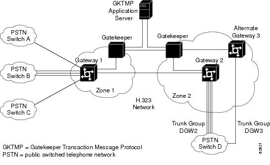
The RAS message includes a new field called circuitInfo. The information in the circuitInfo field corresponds to the information in the Q and J tags in the GKTMP message. The trunk group label (Q tag) or carrier ID (J tag) of the primary gateway is provided in the alternateEndpoint structure of the GKTMP message, along with the call signal address of the primary gateway. The trunk group label or carrier ID of each alternate gateway is also provided in the alternateEndpoint structure of the GKTMP message. The Q and J tags of each alternate gateway are embedded inside the existing A-tagged fields of the GKTMP message, as shown in the following example:
A=c:{I:172.18.194.1:1720} J:CARRIER_ID
A=c:{I:10.1.1.1:1720}   Q:TRUNK_GROUP_LABEL
The following is an example of a RAS message from a gatekeeper to a requesting gateway. (The gatekeeper has converted the information in the Q and J fields of the GKTMP message that it received from the GKTMP application server.) The RAS message contains two alternate endpoints, each of which has a circuitInfo field:
alternateEndpoints
 callSignalAddress
  ipAddress :
   'AC12C826'H
   port 1720
  circuitInfo
   destinationCircuitID
    group
     group "CARRIER_ID"
!
 callSignalAddress
  ipAddress :
   ip 'AC12C816'H
   port 1720
  circuitInfo
   destinationCircuitID
    group
     group "TRUNK_GROUP_LABEL"
Limitations for Alternate Endpoints
The gatekeeper can be instructed by GKTMP servers to send alternate endpoints with same call signaling address and different calling or called numbers in the ACF. When this happens the Cisco gateway acting as the endpoint will send an alternate endpoint attempt to the same call signaling address as the primary call. If the first call is still active on the terminating gateway when the second call arrives the TGW would detect a call loop because the calls share the same GUID, and the second call will be rejected with a 'CALL_LOOP' message printed on syslog.
- Effective with Cisco IOS Release 12.4(9)T2 and before, the first call can be active on the TGW when the second call arrives in the following cases.
- A Release Complete message has been sent on the first call, but the TGW keeps the call active till a Release Complete message arrives from OGW or till the release timer expires.
- A Release Complete message has been sent out on the first call, but a DRQ has not arrived from the GK.
- Effective with Cisco IOS Release 12.4(9)T3 and later, the first call can be active on the TGW when the second call arrives because:
- The TGW keeps the call active if Maintain connection timeout is turned off, even if a Release Complete message has been sent on the first call. The call is kept active till a Release Complete message arrives from OGW or till the release timer expires.
- A Release Complete message has been sent out on the first call, but a DRQ has not arrived from the GK.
Carrier-Based Routing Without a GKTMP Application Server
Carrier-based routing is possible without the presence of the GKTMP application server if you have Cisco IOS Release 12.3(8)T1, Cisco IOS Release 12.3(11)T, or higher. The trunk group label or carrier ID of the terminating gateway can also be provided by the destination circuitInfo field in ARQ. Incoming ARQ to the gatekeeper has the destination circuitInfo field. When both GKTMP and incoming ARQ provide the trunk group ID or carrier ID, the ID provided by the GKTMP server is accepted. The GKTMP server can also add, modify, or delete the trunk group ID or carrier ID present in ARQ using RESPONSE ARQ or ACF message. If the RESPONSE ARQ or the ACF message does not include a Q or J tag, only the trunk group or carrier ID provided by the incoming ARQ is used for routing.
Additional Routes to Alternate Endpoints
The Location Confirmation Enhancements for Alternate Endpoints feature allows a Cisco IOS gatekeeper to collect additional routes to endpoints that are indicated by multiple location confirmation (LCF) responses from remote gatekeepers and convey a collection of those routes to the requesting (calling) endpoint. Currently, the originating gatekeeper sends Location Request (LRQ) messages to multiple remote zones. Remote gatekeepers in the zones return LCF responses to the originating gatekeeper. The LCF responses indicate alternate routes to the endpoints of the remote gatekeeper. The consolidation of LCF responses to multiple LRQ messages can provide many alternate routes to reach a given destination. An endpoint can have up to 20 alternate endpoints.
The remote gatekeeper zones have been configured in the originating gatekeeper using the zone remote command, specifying the cost and priority to each remote zone. After receiving the LCF responses, the originating gatekeeper determines the best route to an endpoint on the basis of the cost and priority of remote zones returning the responses. The originating gatekeeper then forwards route information to the requesting endpoint in the Admission Confirmation (ACF) message, which contains an ordered list of alternate endpoints.
The Location Confirmation Enhancements for Alternate Endpoints feature allows the originating gatekeeper to discover and relay more possible terminating endpoints to the requesting endpoint, therefore providing alternate routes to endpoints that can be used if the best route is busy or does not provide any alternate routes. The endpoint that receives the list of alternate endpoints tries to reach them in the order in which the alternate endpoints were received. The Location Confirmation Enhancements for Alternate Endpoints feature can be used on gatekeepers that originate LRQ messages and directory gatekeepers that forward LRQ messages.
The Location Confirmation Enhancements for Alternate Endpoints feature allows you to choose the number of alternate routes you want the gatekeeper to collect during the existing LRQ timer window. When the timer expires or the best response and sufficient alternates are received, the resolved address and alternate endpoints from all the LCFs received by the gatekeeper are consolidated in a single list. Identical alternate endpoints are removed from the list. That is, if an alternate endpoint that was received in an LCF message has an identical IP address or trunk group label or carrier ID as any alternate endpoints received in previous LCF messages, the previous duplicate alternate endpoints are removed from the consolidated list.
The address and endpoints are sent as alternate endpoints in the ACF or LCF messages from the gatekeeper. If this feature is not enabled, the gatekeeper stops collecting routes after the LRQ timer expires and then chooses the best LCF and sends it in the ACF message. After you enable the feature, the gatekeeper stops collecting routes after the LRQ timer expires and then consolidates the endpoints from all LCF messages received.
Note |
Annex G border element (BE) interaction is not affected. The LCF responses from BEs are treated like any remote gatekeeper LCF. |
Effective with Cisco IOS Release 12.2(11)T, duplicate alternate endpoints that are received in a Location Confirmation (LCF) message are removed from the consolidated list of endpoints. The current gatekeeper limitations apply:
- Ten LRQ messages can be sent by the gatekeeper; therefore, there is a limit of 10 remote zones that are handled by the gatekeeper.
- ACF and LCF messages can carry up to 20 alternate endpoints.
Nonavailability Information for Terminating Endpoints
An H.323 Location Request (LRQ) message is sent by a gatekeeper to another gatekeeper to request a terminating endpoint. The second gatekeeper determines the appropriate endpoint on the basis of the information contained in the LRQ message. However, sometimes all the terminating endpoints are busy servicing other calls and none are available. If you configure the lrq reject-resource-low command, the second gatekeeper rejects the LRQ request if no terminating endpoints are available. If the command is not configured, the second gatekeeper allocates and returns a terminating endpoint address to the sending gatekeeper even if all the terminating endpoints are busy. A call has a higher chance of succeeding if the availability of the endpoint is determined in advance. Returned addresses are only those that have available capacity. Rejecting an LRQ message forces the sending gatekeeper to query other gatekeepers to find an endpoint that has available capacity.
Endpoint-Based Call-Capacity Management
Gatekeepers can currently provide dynamic calculation of maximum calls for endpoints that report v4 call capacity in Registration, Admission, and Status (RAS) messages. This enhancement enables the static assignment of a maximum number of calls to an endpoint and the dynamic calculation of maximum calls to be overridden for an endpoint. You can also statically assign maximum calls to non-v4 endpoints that do not report call capacity and to override the dynamic calculation of maximum calls for an endpoint that does report call capacity. The endpoint circuit-id h323id command is used to configure the dynamic calculation of maximum calls.
While managing endpoint call capacity, a gatekeeper uses one of two different fields of the endpoint structure to store endpoint call capacity (based on the flag voice_GwCallsAvailable_present and h323_GwCallsAvailable_present of call capacity reported by an endpoint). If the Endpoint-Based Call Capacity Management feature is used to configure maximum calls, the gatekeeper stores endpoint call capacity in the field that is already in use (e_voiceCallCapacity and e_h323CallCapacity). If no field is in use (if the endpoint is not reporting call capacity), the gatekeeper uses the field associated with the time-division multiplexing (TDM) gateway (this is e_voiceCallCapacity) to store endpoint call capacity.
A gatekeeper also does active call counting for carrier-based routing when an endpoint reports capacity or carrier ID information in an ARQ or disengage request (DRQ) message or is statically configured for carrier ID and maximum call. Call accounting is extended if an endpoint does not report capacity or carrier ID information in the ARQ or DRQ message or is not statically configured for carrier ID and maximum calls. The show gatekeeper endpoints command displays the current call count for the endpoint. The current call should be updated for the call reported using the information response (IRR) message.
Gatekeeper resource monitoring is enabled using the endpoint resource-threshold onsetcommand. If the command is configured, a gatekeeper currently indicates that a gateway is "out-of-resource" when the available call percentage is less than the configured value. For prefix-based routing, nothing special needs to be configured for the gatekeeper to select a local destination gateway. For carrier-based routing, before selecting a local destination endpoint, a gatekeeper currently checks to ensure that the endpoint is not out-of-resource for the destination carrier. The gatekeeper must perform an additional check to ensure that the endpoint is not out-of-resource (as reported through the Resource Availability Indicator (RAI) out-of-resource flag).
Configuring Alternate Endpoints
To configure alternate endpoints, use the following commands beginning in global configuration mode.
DETAILED STEPS
| Command or Action | Purpose | |
|---|---|---|
|
Step 1
|
gatekeeper
Example: Router (config)# gatekeeper |
Enters gatekeeper configuration mode. |
|
Step 2
|
endpoint alt-ep h323id h323-id ip-address [port] [carrier-id carriername]
Example: Router (config-gk)# endpoint alt-ep h323id h323-id 192.168.0.0 |
Configures alternate endpoints. Keywords and arguments are as follows:
|
|
Step 3
|
exit
Example: Router (config-gk)# exit |
Exits the current mode. |
Verifying Alternate Endpoints
DETAILED STEPS
|
show gatekeeper endpoints alternates
Use this command to display the status of all registered endpoints for a gatekeeper. The following example shows three carrier IDs (CARRIER_ABC, CARRIER_DEF, and CARRIER_GHI): Example:
Router# show gatekeeper endpoints alternates
                    GATEKEEPER ENDPOINT REGISTRATION
                    ==================================
CallSignalAddr  Port  RASSignalAddr   Port  Zone Name   Type   Flags
-------------------  -----  -------------------    ----  --------------   ------   ------
!
ALL CONFIGURED ALTERNATE ENDPOINTS
                   ==================================
Endpoint H323 Id                RASSignalAddr    Port     Carrier Id
----------------------                -------------------    -----      -----------
gwid                                    1.1.1.1                  1720    CARRIER_ABC
gwid                                    1.1.1.1                  1720    CARRIER_DEF
gwid                                    2.2.2.2                  1720    CARRIER_GHI
|
Configuring Additional Routes to Alternate Endpoints
To configure a collection of alternate endpoints, use the following commands beginning in global configuration mode.
DETAILED STEPS
| Command or Action | Purpose | |
|---|---|---|
|
Step 1
|
gatekeeper
Example: Router (config)# gatekeeper |
Enters gatekeeper configuration mode. |
|
Step 2
|
endpoint alt-ep collect value [distribute]
Example: Router(config-gk)# endpoint alt-ep collect 20 |
Configures the number of alternate routes to consolidate from various LCF responses before ending the collection process and sending the LCF message to the requesting endpoint. Keywords and arguments are as follows:
Identical alternate endpoints are removed from the list. That is, if an alternate endpoint received in an LCF message has an identical IP address or trunk group label or carrier ID as any alternate endpoints received in previous LCF messages, the previous duplicate alternate endpoints are removed from the consolidated list.
|
|
Step 3
|
exit
Example: Router (config-gk)# exit |
Exits the current mode. |
Configuring Nonavailability Information for Terminating Endpoints
To configure a gatekeeper to notify a sending gatekeeper on receipt of an LRQ message that no terminating endpoints are available, use the following commands beginning in global configuration mode.
DETAILED STEPS
| Command or Action | Purpose | |
|---|---|---|
|
Step 1
|
gatekeeper
Example: Router (config)# gatekeeper |
Enters gatekeeper configuration mode. |
|
Step 2
|
lrq reject-resource-low
Example: Router (config-gk)# lrq reject-resource-low |
Configures the gatekeeper to notify a sending gatekeeper on receipt of an LRQ message that no terminating endpoints are available. |
|
Step 3
|
exit
Example: Router (config-gk)# exit |
Exits the current mode. |
Verifying the Sending of Nonavailability Information
DETAILED STEPS
|
show running-config
Use this command to verify that the gatekeeper is configured to notify a sending gatekeeper on receipt of an LRQ message that no terminating endpoints are available. |
Configuring Endpoint-Based Call-Capacity Management
Note |
The endpoint resource-threshold onset command must be configured for the gatekeeper to perform endpoint-based call-capacity management. |
To configure endpoint-based call-capacity management, use the following commands beginning in global configuration mode.
DETAILED STEPS
| Command or Action | Purpose | |
|---|---|---|
|
Step 1
|
gatekeeper
Example: Router(config)# gatekeeper |
Enters gatekeeper configuration mode. |
|
Step 2
|
endpoint max-calls h323id endpoint-id max-calls
Example: Router(config-gk)# endpoint max-calls h323id GW-1 1000 |
Sets the maximum number of calls that are allowed for an endpoint. Arguments are as follows:
|
|
Step 3
|
exit
Example: Router(config-gk)# exit |
Exits the current mode. |
Forcing Endpoint Unregistration
To force a gatekeeper to unregister an endpoint, use the clear h323 gatekeeper endpoint command as described below. Alternatively, you can issue a command from the GKTMP server to unregister an endpoint.
Note |
For more information on GKTMP, see the Cisco Gatekeeper External Interface Reference , Version 4.4 at http://www.cisco.com/en/US/docs/ios/12_3/gktmpv4_3/guide/gktmp4_3.html . |
Prerequisites for Forcing Unregistration
For gatekeeper cluster configurations, the clear h323 gatekeeper endpoint command must be entered on the gatekeeper where the endpoint is registered. Use the show gatekeeper endpoints command to locate the endpoint in a gatekeeper cluster.
DETAILED STEPS
| Command or Action | Purpose | |
|---|---|---|
|
Step 1
|
clear h323 gatekeeper endpoint {alias {e164 name | h323id name} | all | id number | ipaddr ip-address [port]}
Example: Router# clear h323 gatekeeper endpoint all |
Forces the gatekeeper to send an unregistration request (URQ) message to the specified endpoint or all endpoints and removes the endpoint from the gatekeeper registration database. The endpoint that is unregistered can come back if it sends the RRQ message back to the gatekeeper after unregistration. Keywords and arguments are as follows:
|
Verifying Endpoint Unregistration
DETAILED STEPS
| Step 1 | Verify that you did not receive an error message after entering the clear h323 gatekeeper endpointcommand. |
| Step 2 | show gatekeeper endpoints Use this command to view all endpoints registered to the gatekeeper: Example:
Router# show gatekeeper endpoints
GATEKEEPER ENDPOINT REGISTRATION
                    ================================
CallSignalAddr  Port  RASSignalAddr   Port  Zone Name         Type
Flags
--------------- ----- --------------- ----- ---------         ----
-----
1.1.1.1         1720  1.1.1.1         1719  gk-e4-2           VOIP-GW S
    H323-ID: test (static)
Total number of active registrations = 1
|
| Step 3 | Verify that the unregistered endpoint is not displayed in the list of endpoints. |
Configuring the IRR Timer and Disable IRQ Requests
This section contains the following information:
- Restrictions for the IRR Timer and Disable IRQ Requests
- Information About the IRR Timer and Disable IRQ Requests
- Configuring IRR Periodic Intervals on the Gatekeeper
- Disabling IRQ Requests for All Calls in the Gatekeeper
Restrictions for the IRR Timer and Disable IRQ Requests
- If the gatekeeper is configured to not send IRQs with the CRV set to zero, bandwidth control is not supported.
- Adjusting the IRR frequency while there are existing calls should be avoided.
- All gatekeepers should have the same IRR frequency configured to prevent problems during gatekeeper switchover.
- RQ retries from two to nine increases DRQ reliability. This value is not configurable.
Information About the IRR Timer and Disable IRQ Requests
Call Status Tracking Optimization reduces unnecessary messages between gatekeeper and the gateways, reducing network congestion and CPU over-utilization.
In an H.323 VoIP network, gatekeepers use information request (IRQ) messages to obtain information about a certain call or all calls from an endpoint (for example, an originating gateway). The gatekeeper can send an IRQ to request information from the endpoint, which responds with an information request response (IRR). The gatekeeper can also use the irrFrequency field in the initial admission confirm (ACF) message to instruct the endpoint to periodically report with IRR messages during call admission.
Currently, the Cisco gatekeeper maintains the call states of all calls it has admitted, to track bandwidth usage. In addition, the gatekeeper must be able to reconstruct call structures for a newly transferred gateway from an alternate gatekeeper, if a gatekeeper switchover has occurred. In a gatekeeper switchover, the new gatekeeper sends an IRQ message with the call reference value (CRV) set to 0 to the newly registered gateway to obtain information about existing calls before the switchover.
If a gateway supports a large volume of calls, the number of IRR messages as responses to an IRQ with the CRV set to zero could be very CPU intensive and cause congestion. Additionally, if a gatekeeper serves many endpoints or high-capacity gateways, the IRQ requests and the resulting IRR messages received can flood the network, causing high CPU utilization and network congestion.
The Call Status Tracking Optimization feature provides the following methods to address this potential problem:
- A command to configure IRR frequency that is included in the ACF message. Currently, the IRR frequency is set to 240 seconds (4 minutes), based on an average 4-minute call hold time. The IRR allows the gatekeepers to terminate calls for which a disengage request (DRQ) has not been received. If missing DRQs are not a problem, the IRR frequency can be set to a larger value than four minutes, minimizing the number of unnecessary IRRs sent by a gateway.
- A command to disable the gatekeeper from sending an IRQ with the CRV set to zero when the gatekeeper is requesting the status of all calls after its initialization. Disabling the IRQ can eliminate unnecessary IRR messages in cases where the reconstruction of call structures can be postponed until the next IRR, or in cases where the call information is no longer required because calls are terminated before the periodic IRR is sent. Disabling the IRQ is advantageous if direct bandwidth control is not used in the gatekeeper.
- An increase from two to nine in the number of retries for sending the DRQ. If the reliability of DRQ messages is increased, a longer period can be used before the next IRR is sent. Third-party gatekeepers must support this feature.
Configuring IRR Periodic Intervals on the Gatekeeper
To configure IRR periodic intervals on the gatekeeper, use the following commands beginning in global configuration mode.
DETAILED STEPS
| Command or Action | Purpose | |
|---|---|---|
|
Step 1
|
gatekeeper
Example: Router(config)# gatekeeper |
Enters gatekeeper configuration mode. |
|
Step 2
|
timer irr period value
Example: Router(config-gk)# timer irr period 30 |
Configures the IRR timer, or the periodic interval of IRR messages sent by the gatekeeper, in minutes. The gatekeeper uses this value to populate the irrFrequency field in the ACF message. Range: 1 to 60. Default: 4. |
|
Step 3
|
exit
Example: Router(config-gk)# exit |
Exits the current mode. |
Disabling IRQ Requests for All Calls in the Gatekeeper
To disable IRQ requests for all calls in the gatekeeper, use the following commands beginning in global configuration mode.
DETAILED STEPS
| Command or Action | Purpose | |
|---|---|---|
|
Step 1
|
gatekeeper
Example: Router(config)# gatekeeper |
Enters gatekeeper configuration mode. |
|
Step 2
|
no irq global-request
Example: Router(config-gk)# no irq global-request |
Prohibits the gatekeeper from sending IRQ requests with a CRV set to zero to endpoints to obtain information about all calls. These IRQ requests are usually sent after a gatekeeper initializes upon switchover. Default: sends IRQ requests with a CRV set to zero. |
|
Step 3
|
exit
Example: Router(config-gk)# exit |
Exits the current mode. |
Configuring Sequential LRQs
This section contains the following information:
- Restrictions for Sequential LRQs
- Information About Sequential LRQs
- Configuring Sequential LRQ Enhancement
- Configuring the Sequential LRQ Timer
- Verifying Sequential LRQ Enhancement
Restrictions for Sequential LRQs
- In a network where LRQs are forwarded through multiple gatekeepers along a single path, a single LRQ sent from a gatekeeper could solicit multiple LRJ and Location Confirmation (LCF) responses. If an LRJ response is received first, a potentially unnecessary LRQ could be sent to the next zone, increasing traffic.
To avoid this problem, ensure that the gatekeepers do not use the blast option, or carefully configure the sequential timer on each gatekeeper along the path. Using sequential LRQs in a directory gatekeeper along the path can also help because sequential LRQs in the directory gatekeeper always send one response back to an LRQ request.
Information About Sequential LRQs
You can configure the gatekeeper to provide a potentially faster LRQ response to the originator of the request when a location reject (LRJ) response is received while the gatekeeper is sending sequential LRQs. The Sequential LRQ Enhancement feature introduces a fixed delay for the gatekeeper to send sequential LRQs to successive zones even when a negative response or an LRJ is received from the current zone.
You configure this fixed delay using the lrq lrj immediate-advance command. If an LRJ is received from the current zone, the gatekeeper assumes that the current zone cannot satisfy the request and immediately sends an LRQ to the next zone. This feature works for both typical and directory gatekeepers.
The "Call Flow Using Sequential LRQ Enhancement Feature" section shows how the Sequential LRQ Enhancement feature affects call flows. The originating gatekeeper sends LRQ1 to the first gatekeeper. GK1 responds with LRJ1. Immediately upon receipt of LRJ1, the originating gatekeeper sends LRQ2 to GK2.
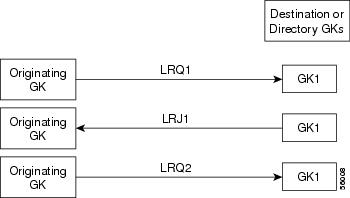
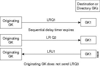
Configuring Sequential LRQ Enhancement
To configure sequential LRQ enhancement, use the following commands beginning in global configuration mode.
DETAILED STEPS
| Command or Action | Purpose | |
|---|---|---|
|
Step 1
|
gatekeeper
Example: Router(config)# gatekeeper |
Enters gatekeeper configuration mode. |
|
Step 2
|
lrq lrj immediate-advance
Example: Router(config-gk)# lrq lrj immediate-advance |
Enables the GK to immediately send an LRQ to the next zone after it receives an LRJ from a GK in the current zone. |
|
Step 3
|
exit
Example: Router(config-gk)# exit |
Exits the current mode. |
Configuring the Sequential LRQ Timer
To configure the sequential LRQ timer, use the following commands beginning in global configuration mode.
DETAILED STEPS
| Command or Action | Purpose | |
|---|---|---|
|
Step 1
|
gatekeeper
Example: Router(config)# gatekeeper |
Enters gatekeeper configuration mode. |
|
Step 2
|
timer lrq seq delay time-in-100-ms-units
Example: Router(config-gk)# timer lrq seq delay 3 |
Defines the intervals for the GK to send successive sequential LRQs. The LRQ sequential timing source (SEQ) delay is used to set the time between sending LRQs to remote gatekeepers for address resolution. To resolve an address, the gatekeeper might have several remote zones configured, and it can send the LRQs simultaneously (blast) or sequentially (seq). The gatekeeper chooses the best route based on availability and cost. Using LRQs sequentially results in lower network traffic, but can increase latency of calls when the most preferred route is unavailable. The argument is as follows:
Lowering the time increases traffic on the network but might reduce call-setup time. |
|
Step 3
|
exit
Example: Router(config-gk)# exit |
Exits the current mode. |
Verifying Sequential LRQ Enhancement
DETAILED STEPS
|
show running-config
Use this command to verify that the Sequential LRQ Enhancement feature is enabled. Example:
Router# show running-config
Building configuration...
Current configuration : 1802 bytes
!
version 12.2
.
.
.
gatekeeper
 zone local Zone1 cisco.com
 zone remote c3620-1-gk cisco.com 209.165.200.225 1719
 zone remote c2514-2-gk cisco.com 209.165.200.228 1719
 zone remote gk-cisco-mn cisco.com 209.165.200.230 1719
 zone remote gkzone3 cisco.com 209.165.200.235
 zone remote gk-catapult cisco.com 209.165.200.229 1719
 zone prefix gkzone3 405.......
 zone prefix gk-gk5 515....
 zone prefix c2514-2-gk 910.......
 zone prefix c3620-1-gk 917300....
 zone prefix c2514-2-gk 919.......
 zone prefix gk-cisco-mn 919.......
 zone prefix c3620-1-gk 919.......
 lrq reject-resource-low
 lrq lrj immediate-advance
 timer lrq window 6
 no shutdown
.
.
.
|
Configuration Examples for H.323 Gatekeepers and Proxies
- HSRP Example
- Gatekeeper Zones Example
- Load Balancing with Alternate Gatekeepers Example
- Security and Authentication Example
- E.164 Interzone Routing Example
- Interaction with External Applications Example
- Proxy Use Example
- Co-Edge Proxy Example
- Endpoints Example
- IRR Timer and Disable IRQ Requests Example
- Sequential LRQ Enhancement Example
HSRP Example
Primary Gatekeeper
configure terminal
 ! Enter global configuration mode.
interface ethernet 0
 ! enter interface configuration mode for interface ethernet 0.
 standby 1 ip 172.21.127.55
 ! Member of standby group 1, sharing virtual address 172.21.127.55.
 standby 1 preempt
 ! Claim active role when it has higher priority.
 standby 1 timers 5 15
 ! Hello timer is 5 seconds; hold timer is 15 seconds.
 standby 1 priority 110
 ! Priority is 110.
Backup Gatekeeper
configure terminal
interface ethernet 0
 standby 1 ip 172.21.127.55
 standby 1 preempt
 standby 1 timers 5 15
The configurations are identical except that gk2 has no standby priority configuration, so it assumes the default priority of 100--meaning that gk1 has a higher priority.
gk1 and gk2 Gatekeeper Mode Configurations
configure terminal
 ! Enter global configuration mode.
gatekeeper
 ! Enter gatekeeper configuration mode.
 zone local gk-sj cisco.com 172.21.127.55
 ! Define local zone using HSRP virtual address as gatekeeper RAS address.
.
.
.
 ! Various other gk-mode configurations.
 no shut
 ! Bring up the gatekeeper.
configure terminal
 ! Enter global configuration mode.
gatekeeper
 ! Enter gatekeeper configuration mode.
 zone local gk-sj cisco.com 172.21.127.55
 ! Define local zone using HSRP virtual address as gatekeeper RAS address.
 ! Note this uses the same gkname and address as on gk1.
.
.
! Various other gk-mode configurations.
 no shut
 ! Bring up the gatekeeper.
Note |
The no shut commandis issued on both gatekeepers, primary and secondary. If the show gatekeeper statuscommand is issued on the two gatekeepers, gk1 shows the following: |
Gatekeeper State: UP
! But gk2 shows the following:
Gatekeeper State: HSRP STANDBY
Gatekeeper Zones Example
Multiple Zones
The following example shows how to define multiple local zones for separating gateways:
zone local gk408or650 xyz.com
zone local gk415 xyz.com
zone prefix gk408or650 408.......
zone prefix gk408or650 650.......
zone prefix gk415 415.......
All the gateways used for area codes 408 or 650 can be configured so that they register with gk408or650, and all gateways used for area code 415 can be configured so that they register with gk415.
One Zone for Multiple Gateways
The following example shows how to put all the gateways in the same zone and use the gw-priority keyword to determine which gateways are used for calling different area codes:
zone local localgk xyz.com
zone prefix localgk 408.......
zone prefix localgk 415....... gw-priority 10 gw1 gw2
zone prefix localgk 650....... gw-priority 0 gw1
The commands shown accomplish the following tasks:
- Domain xyz.com is assigned to gatekeeper localgk.
- Prefix 408....... is assigned to gatekeeper localgk, and no gateway priorities are defined for it; therefore, all gateways that register to localgk can be used equally for calls to the 408 area code. No special gateway lists are built for the 408....... prefix; selection is made from the master list for the zone.
- The prefix 415....... is added to gatekeeper localgk, and priority 10 is assigned to gateways gw1 and gw2.
- Prefix 650....... is added to gatekeeper localgk, and priority 0 is assigned to gateway gw1.
A priority 0 is assigned to gateway gw1 to exclude it from the gateway pool for prefix 650........ When gateway gw2 registers with gatekeeper localgk, it is added to the gateway pool for each prefix as follows:
- For gateway pool for 415......., gateway gw2 is set to priority 10.
- For gateway pool for 650......., gateway gw2 is set to priority 5.
To change gateway gw2 from priority 10 for zone 415....... to the default priority 5, enter the following command:
no zone prefix localgk 415....... gw-pri 10 gw2
To change both gateways gw1 and gw2 from priority 10 for zone 415....... to the default priority 5, enter the following command:
no zone prefix localgk 415....... gw-pri 10 gw1 gw2
In the preceding example, the prefix 415....... remains assigned to gatekeeper localgk. All gateways that do not specify a priority level for this prefix are assigned a default priority of 5. To remove the prefix and all associated gateways and priorities from this gatekeeper, enter the following command:
no zone prefix localgk 415.......
Session Bandwidth Limits
The following example shows session bandwidth limits and resource information for destination zones configured on the gatekeeper:
Router# show running-config
!
Building configuration...
Current configuration : 1329 bytes
!
version 12.3
service timestamps debug uptime
service timestamps log uptime
no service password-encryption
!
hostname router
!
username all
memory-size iomem 10
clock timezone GMT 0
aaa new-model
!
aaa accounting connection h323 stop-only group radius
aaa session-id common
ip subnet-zero
!
no ip domain lookup
ip domain name cisco.com
ip host anyname-tftp1 172.18.207.15
ip dhcp smart-relay
!
voice call carrier capacity active
voice service voip
 sip
 session transport tcp
 rel1xx disable
!
interface Ethernet0/0
 ip address 172.18.200.28 255.255.255.0
 half-duplex
 no cdp enable
!
interface TokenRing0/0
 no ip address
 shutdown
 ring-speed 16
 no cdp enable
!
no ip http server
ip classless
ip route 0.0.0.0 0.0.0.0 172.18.200.1
!
radius-server host 172.18.200.30 auth-port 1645 acct-port 1646
radius-server vsa send accounting
!
dial-peer cor custom
!
gatekeeper
 zone local GK-1 cisco.com 172.18.200.28
 zone local GK-2 cisco.com
 zone local word word
 zone remote GK-3 cisco.com 172.18.200.5 1719
 zone prefix GK-2 1..
 gw-type-prefix 1#* default-technology
 bandwidth interzone default 1
 bandwidth session default 5
 bandwidth remote 4
 no shutdown
 server registration-port 21000
!
line con 0
 exec-timeout 0 0
line aux 0
line vty 0 4
 password lab
 line vty 5 15
!end
Load Balancing with Alternate Gatekeepers Example
Redundant Gatekeepers for a Zone Prefix
In the following example, two remote gatekeepers are configured to service the same zone prefix:
gatekeeper
 zone remote c2600-1-gk cisco.com 172.18.194.70 1719
 zone remote c2514-1-gk cisco.com 172.18.194.71 1719
 zone prefix c2600-1-gk 919.......
 zone prefix c2514-1-gk 919.......
Redundant Gatekeepers for a Technology Prefix
In the following example, two remote gatekeepers are configured to service the same technology prefix:
gatekeeper
 zone remote c2600-1-gk cisco.com 172.18.194.70 1719
 zone remote c2514-1-gk cisco.com 172.18.194.71 1719
 gw-type-prefix 3#* hopoff c2600-1-gk hopoff c2514-1-gk
Security and Authentication Example
Domain Zones and the IZCT Password
All of the configuration examples are for the figure below. One IZCT password is enabled for all of the gatekeepers.
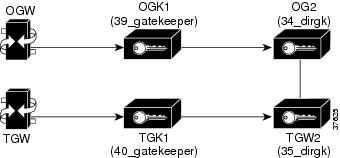
Originating Gatekeeper 1
config terminal
gatekeeper
 zone local 39_gatekeeper cisco.com 172.18.198.92
 zone remote 34_dirgk cisco.com 172.18.198.197 1719
 zone prefix 39_gatekeeper 919*
 zone prefix 34_dirgk *
 security izct password cisco
 gw-type-prefix 1#* default-technology
 no shutdown
Terminating Gatekeeper 1
config terminal
gatekeeper
zone local 40_gatekeeper cisco.com 172.18.198.91
 zone remote 35_dirgk cisco.com 172.18.198.196 1719
 zone prefix 40_gatekeeper 408*
 zone prefix 35_dirgk *
 security izct password cisco
 gw-type-prefix 1#* default-technology
 no shutdown
Originating Gatekeeper 2
config terminal
gatekeeper
zone local 34_dirgk cisco.com 172.18.198.197
 zone remote 39_gatekeeper cisco.com 172.18.198.92 1719
 zone remote 35_dirgk cisco.com 172.18.198.196 1719
 zone prefix 39_gatekeeper 919*
 zone prefix 35_dirgk *
 security izct password cisco
 lrq forward-queries
 no shutdown
Terminating Gatekeeper 2
config terminal
gatekeeper
 zone local 35_dirgk cisco.com 172.18.198.196
 zone remote 40_gatekeeper cisco.com 172.18.198.91 1719
 zone remote 34_dirgk cisco.com 172.18.198.197 1719 foreign-domain
 zone prefix 40_gatekeeper 408*
 zone prefix 34_dirgk *
 security izct password cisco
 lrq forward-queries
 no shutdown
Cisco Access Tokens
Note |
The following examples do not reflect the actual display of thepasswords as you would see them in output. Actual displays show the passwords as being encrypted. The displays here show them in cleartext format for clarity purposes only. |
Originating Gatekeeper
In this example, LRQ messages received from the border gatekeeper authenticate the LRQ message by using the password "ogk_123." LRQ messages sent to the border gatekeeper contain the password "bgk_123" in the CAT.
gatekeeper
 zone remote bgk china 172.18.195.137 1719 foreign-domain
 security password-group china lrq send bgk_123
 security password-group china lrq receive ogk_123
 security zone bgk password-group china
Border Gatekeeper Configuration
In this example, LRQ messages received from the originating gatekeeper authenticate the LRQ message by using the password "bgk_123." LRQ messages sent to the originating gatekeeper contain the password "ogk_123" in the CAT. LRQ messages received from the terminating gatekeeper authenticate the LRQ message by using the password "bgk_123." LRQ messages sent to the terminating gatekeeper contain the password "tgk_123" in the CAT.
gatekeeper
 zone remote ogk usa 172.18.195.138 1719 foreign-domain
 zone remote tgk china 172.18.195.139 1719
 security password-group usa lrq send ogk_123
 security password-group usa lrq receive bgk_123
 security password-group china lrq send tgk_123
 security password-group china lrq receive bgk_123
 security zone ogk password-group usa
 security zone tgk password-group china
Terminating Gatekeeper Configuration
In this example, LRQ messages received from the border gatekeeper authenticate the LRQ message by using the password "tgk_123." LRQ messages sent to the border gatekeeper contain the password "bgk_123" in the CAT.
gatekeeper
 zone remote bgk china 172.18.195.137 1719
 security password-group china lrq send bgk_123
 security password-group china lrq receive tgk_123
 security zone bgk password-group china
Gatekeeper Configuration Using the Wildcard
In this example, LRQ messages are received from the terminating gatekeeper, which does not have a password group configured. Therefore, the LRQ messages received are authenticated using the password group configured for the originating gatekeeper (in this example, "ogk_123").
gatekeeper
 zone remote tgk china 172.18.195.137 1719 foreign-domain
 security password-group china lrq send tgk_123
 security password-group china lrq receive ogk_123
 security zone * password-group china
Tokenless Call Authorization
Tokenless Call Authorization
The following example shows how to configure tokenless call authorization. You create an IP ACL containing endpoints from which the gatekeeper should accept calls. After the router enters gatekeeper configuration mode, you instruct the gatekeeper to check the ACL before processing the call.
Router# enable
Router# configure terminal
Router(config)# access-list 20 permit 172.16.10.190
Router(config)# access-list 20 permit 192.16.18.2
Router(config)# access-list 20 permit 192.16.10.12
Router(config)# access-list 20 permit 192.16.12.1
Router(config)# gatekeeper
Router(config-gk)# security acl answerarq 20
IP Access Lists
The following example shows how to verify the IP access lists and that the gatekeeper has been configured to use them:
Router# show running-config
Building configuration...
.
.
.
ip access-list standard WORD
!
access-list 20 permit 172.16.10.190
access-list 20 permit 192.16.18.2
access-list 20 permit 192.16.10.12
access-list 20 permit 192.16.12.1
.
.
.
gatekeeper
 zone local herndon.cisco.com cisco.com
 security acl answerarq 20
 no shutdown
.
.
.
end
E.164 Interzone Routing Example
Interzone routing may be configured by using E.164 addresses.
In this example, there are two gatekeepers that need to be able to resolve E.164 addresses. One is in San Jose and the other is in New York. (See the figure below.)
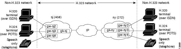
In sj (San Jose in the 408 area code), the gateways are configured to register with gk-sj as follows:
- gw-sj2 configured to register with technology prefix 2#
- gw-sj3 configured to register with technology prefix 3#
- gw-sj4 configured to register with technology prefix 4#
Similarly, in ny (New York in the 212 area code), gateways are configured to register with gk-ny as follows:
- gw-ny2 configured to register with technology prefix 2#
- gw-ny3 configured to register with technology prefix 3#
- gw-ny4 configured to register with technology prefix 4#
For the gatekeeper for San Jose, the configuration commands are as follows:
gatekeeper
 zone local gk-sj cisco.com
 zone remote gk-ny cisco.com 172.21.127.27
 use-proxy gk-sj default direct
 zone prefix gk-sj 408.......
 zone prefix gk-ny 212.......
 gw-type-prefix 3# hopoff gk-sj
 gw-type-prefix 4# default-technology
For the gatekeeper for New York, the configuration commands are as follows:
gatekeeper
 zone local gk-ny cisco.com
 zone remote gk-sj cisco.com 172.21.1.48
 use-proxy gk-ny default direct
 zone prefix gk-sj 408.......
 zone prefix gk-ny 212.......
 gw-type-prefix 3# hopoff gk-ny
 gw-type-prefix 4# default-technology
When a call is presented to gatekeeper gk-sj with the following target address in San Jose:
2#2125551212
Gatekeeper gk-sj recognizes that 2# is a technology prefix. It was not configured as such, but because gw-sj2 registered with it, the gatekeeper now treats 2# as a technology prefix. It strips the prefix, which leaves the telephone number 2125551212. This is matched against the zone prefixes that have been configured. It is a match for 212......., so gk-sj knows that gk-ny handles this call. Gatekeeper gk-sj forwards the entire address 2#2125551212 over to Gatekeeper gk-ny, which also looks at the technology prefix 2# and routes it to gw-ny2.
When a call is presented to gatekeeper gk-sj with the following target address in San Jose:
2125551212
Gatekeeper gk-sj checks it against known technology prefixes but finds no match. It then checks it against zone prefixes and matches on 212....... for gk-ny, and therefore routes this call to gk-ny. Gatekeeper gk-ny does not have any local registrations for this address, and there is no technology prefix on the address, but the default prefix is 4#, and gw-ny4 is registered with 4#, so the call gets routed to gw-ny4.
Another call is presented to gatekeeper gk-sj with the following target address in San Jose:
3#2125551212
The call has technology prefix 3#, which is defined as a local hopoff prefix, so gk-sj routes this call to gw-sj3, despite the fact that it has a New York zone prefix.
In this last example, a call is presented to gatekeeper gk-sj with the following target address in San Jose:
6505551212
Gatekeeper gk-sj checks for a technology prefix match but does not find one. It then searches for a zone prefix match and fails again. But there is a match for default gateway prefix of 4#, and gw-sj4 is registered with 4#, so the call is routed out on gw-sj4.
Interaction with External Applications Example
Gatekeeper Flow Control
In the following example, server flow-control is set with an onset level of 50:
Router# server flow-control onset 50
*Mar  8 20:05:34.081: gk_srv_handle_flowcontrol: Flow control enabled
Router# show running-config
Building configuration...
Current configuration : 1065 bytes
!
version 12.2
no service single-slot-reload-enable
service timestamps debug datetime msec
service timestamps log uptime
no service password-encryption
!
hostname snet-3660-3
!
.
.
.
gatekeeper
 zone local snet-3660-3 cisco.com
 zone remote snet-3660-2 cisco.com 209.165.200.225 1719
 zone prefix snet-3660-2 408*
 lrq forward-queries
 no use-proxy snet-3660-3 default inbound-to terminal
 no use-proxy snet-3660-3 default outbound-from terminal
 no shutdown
 server registration-port 8000
 server flow-control onset 50
!
!
.
.
.
end
Retry Timer
The following example shows that the retry timer has been set to 45 seconds:
.
.
.
gw-type-prefix 1#* default-technology
gw-type-prefix 9#* gw ipaddr 1.1.1.1 1720
timer server retry 45
no shutdown
.
.
.
Registration and Call Rejection
The following example shows that the gatekeeper rejects registrations when it cannot connect to the GKTMP server:
.
.
.
gw-type-prefix 1#* default-technology
gw-type-prefix 9#* gw ipaddr 1.1.1.1 1720
no shutdown
server absent reject rrq
.
.
.
The following example shows that the gatekeeper rejects calls when it cannot connect to the GKTMP server:
.
.
.
gw-type-prefix 1#* default-technology
gw-type-prefix 9#* gw ipaddr 1.1.1.1 1720
no shutdown
server absent reject arq
.
.
.
Proxy Use Example
Proxy for Inbound Calls
In the following example, the local zone sj.xyz.com is configured to use a proxy for inbound calls from remote zones tokyo.xyz.com and milan.xyz.com to gateways in its local zone. The sj.xyz.com zone is also configured to use a proxy for outbound calls from gateways in its local zone to remote zones tokyo.xyz.com and milan.xyz.com.
gatekeeper
use-proxy sj.xyz.com remote-zone tokyo.xyz.com inbound-to gateway
use-proxy sj.xyz.com remote-zone tokyo.xyz.com outbound-from gateway
use-proxy sj.xyz.com remote-zone milan.xyz.com inbound-to gateway
use-proxy sj.xyz.com remote-zone milan.xyz.com outbound-from gateway
Because the default mode disables proxy communications for all gateway calls, only the gateway call scenarios listed can use the proxy.
Proxy for Outbound Calls
In the following example, the local zone sj.xyz.com uses a proxy for only those calls that are outbound from H.323 terminals in its local zone to the specified remote zone germany.xyz.com:
gatekeeper
no use-proxy sj.xyz.com default outbound-from terminal
use-proxy sj.xyz.com remote-zone germany.xyz.com outbound-from
 terminal
Note that any calls inbound to H.323 terminals in the local zone sj.xyz.com from the remote zone germany.xyz.com use the proxy because the default applies.
Proxy Removal
The following example shows how to remove one or more proxy statements for the remote zone germany.xyz.com from the proxy configuration list:
no use-proxy sj.xyz.com remote-zone germany.xyz.com
The command removes all special proxy configurations for the remote zone germany.xyz.com. After the command is entered like this, all calls between the local zone (sj.xyz.com) and germany.xyz.com are processed according to the defaults defined by any use-proxy commands that use the default option.
H.235 Security
The following example shows output from configuring secure registrations from the gatekeeper and identifying which RAS messages the gatekeeper checks to find authentication tokens:
dial-peer voice 10 voip
 destination-pattern 4088000
 session target ras
 dtmf-relay h245-alphanumeric
!
gateway
 security password 09404F0B level endpoint
The following example shows output from configuring which RAS messages contain gateway-generated tokens:
dialer-list 1 protocol ip permit
dialer-list 1 protocol ipx permit
radius-server host 10.0.0.1 auth-port 1645 acct-port 1646
radius-server retransmit 3
radius-server deadtime 5
radius-server key lab
radius-server vsa send accounting
!
gatekeeper
 zone local GK1 test.com 10.0.0.3
 zone remote GK2 test2.com 10.0.2.2 1719
 accounting
 security token required-for registration
 no use-proxy GK1 remote-zone GK2 inbound-to terminal
 no use-proxy GK1 remote-zone GK2 inbound-to gateway
 no shutdown
Prohibition of Proxy Use for Inbound Calls
To prohibit proxy use for inbound calls to H.323 terminals in a local zone from a specified remote zone, enter a command similar to the following:
no use-proxy sj.xyz.com remote-zone germany.xyz.com inbound-to terminal
This command overrides the default and disables proxy use for inbound calls from remote zone germany.xyz.com to all H.323 terminals in the local zone sj.xyz.com.
Co-Edge Proxy Example
Co-Edge Proxy with ASR Without Subnetting
The figure below and the following configuration examples show how to configure RIP on the two edge networks and how to configure IGRP on the two backbone networks.
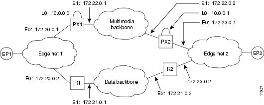
The following output is for the PX1 configuration:
!
proxy h323
!
interface Loopback0
 ip address 10.0.0.0 255.0.0.0
!Assume PX1 is in Zone 1, and the gatekeeper resides in the same routers as PX1:
 h323 interface
 h323 h323-id PX1@zone1.com
 h323 gatekeeper ipaddr 10.0.0.0
!
interface Ethernet0
 ip address 172.20.0.1 255.255.0.0
!
interface Ethernet1
 ip address 172.22.0.1 255.255.0.0
 ip access-group 101 in
 ip access-group 101 out
 h323 asr
!
router rip
 network 172.20.0.0
 network 10.0.0.0
!
router igrp 4000
 network 172.22.0.0
 network 10.0.0.0
!
access-list 101 permit ip any host 10.0.0.0
access-list 101 permit ip host 10.0.0.0 any
access-list 101 permit igrp any any
The following output is for the R1 configuration:
!
interface Ethernet0
 ip address 172.20.0.2 255.255.0.0
!
interface Ethernet1
 ip address 172.21.0.1 255.255.0.0
!
router rip
 redistribute igrp 5000 metric 1
 network 172.20.0.0
!
router igrp 5000
 redistribute rip metric 10000 10 255 255 65535
 network 172.21.0.0
 distribute-list 10 out
!
access-list 10 deny ip 10.0.0.0 255.255.255
access-list 10 permit any
Note |
The configuration for PX2 and R2 is the same as that for PX1 and R1. |
Co-Edge Proxy with Subnetting
The figure below and the examples that follow show how to configure Enhanced IGRP on all networks.
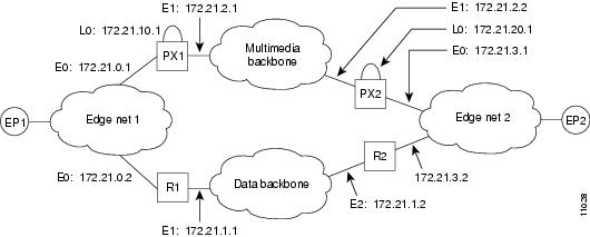
The following output is for the PX1 configuration:
!
proxy h323
!
interface Loopback0
 ip address 172.21.10.1 255.255.255.192
 h323 interface
 h323 h323-id PX1@zone1.com
 h323 gatekeeper ipaddr 172.21.20.1
!
interface Ethernet0
 ip address 172.21.0.1 255.255.255.192
!
interface Ethernet1
 ip address 172.21.2.1 255.255.255.192
 ip access-group 101 in
 ip access-group 101 out
 h323 asr
!
router eigrp 4000
 redistribute connected metric 10000 10 255 255 65535
 passive-interface Ethernet1
 network 172.21.0.0
 distribute-list 10 out
 no auto-summary
!
router eigrp 5000
 redistribute connected metric 10000 10 255 255 65535
 passive-interface Ethernet0
 network 172.21.0.0
 distribute-list 11 out
 no auto-summary
!
access-list 10 deny 172.21.2.0 0.0.0.63
access-list 10 permit any
access-list 11 deny 172.21.0.0 0.0.0.63
access-list 11 permit any
access-list 101 permit ip any host 172.21.10.1
access-list 101 permit ip host 172.21.10.1 any
access-list 101 permit eigrp any any
The following output is for the R1 configuration:
!
interface Ethernet0
 ip address 172.21.0.2 255.255.255.192
!
interface Ethernet1
 ip address 172.21.1.1 255.255.255.192
!
router eigrp 4000
 redistribute eigrp 6000 metric 10000 10 255 255 65535
 passive-interface Ethernet1
 network 172.21.0.0
 no auto-summary
!
router eigrp 6000
 redistribute eigrp 4000 metric 10000 10 255 255 65535
 passive-interface Ethernet0
 network 172.21.0.0
 distribute-list 10 out
 no auto-summary
!
access-list 10 deny 172.21.10.0 0.0.0.63
access-list 10 permit any
Note |
The configuration for PX2 and R2 is the same as that for PX1 and R1. |
Inside-Edge Proxy with ASR Without Subnetting
The configuration of the co-edge proxy in Edge net 1 has already been presented above. The figure below shows the configuration of the inside-edge proxy PX2 and edge router R2 of Edge net 2. RIP is used on the edge networks. IGRP is used on the data backbone and the multimedia backbone.
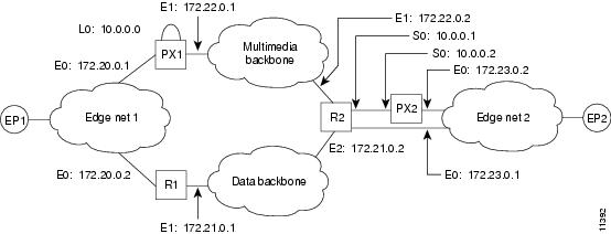
The following output is for the PX2 configuration:
!
proxy h323
!
interface Ethernet0
 ip address 172.23.0.2 255.255.0.0
!
interface Serial0
 ip address 10.0.0.2 255.0.0.0
 ip access-group 101 in
 ip access-group 101 out
 h323 interface
 h323 asr
 h323 h323-id PX2@zone2.com
 h323 gatekeeper ipaddr 10.0.0.2
!
router rip
 redistribute connected metric 10000 10 255 255 65535
 network 172.23.0.0
!
access-list 101 permit ip any host 10.0.0.2
access-list 101 permit ip host 10.0.0.2 any
The following output is for the R2 configuration:
!
interface Ethernet0
 ip address 172.23.0.1 255.255.0.0
!
interface Ethernet1
 ip address 172.22.0.1 255.255.0.0
 ip access-group 101 in
 ip access-group 101 out
!
interface Ethernet2
 ip address 172.21.0.2 255.255.0.0
!
interface Serial0
 ip address 10.0.0.1 255.0.0.0
!
router rip
 redistribute igrp 5000 metric 1
 network 172.23.0.0
!
router igrp 4000
 network 10.0.0.0
 network 172.22.0.0
!
router igrp 5000
 redistribute rip metric 10000 10 255 255 65535
 network 172.21.0.0
 distribute-list 10 out
!
ip route 10.0.0.2 255.255.255.255 Serial0
access-list 10 deny ip 10.0.0.0 255.255.255
access-list 10 permit any
access-list 101 permit ip any host 10.0.0.2
access-list 101 permit ip host 10.0.0.2 any
Note |
To guarantee that all traffic between the proxy and other proxies is carried over the multimedia backbone, run IGRP 4000 on the 10.0.0.0 network and on the 172.22.0.0 network. Make sure that the H.323 proxy interface address (10.0.0.2) is not advertised over the data network (distribution list 10 in IGRP 5000). Doing this also eliminates the need to configure policy routes or static routes. |
QoS-Enforced Open Proxy Using RSVP
The figure below shows a proxy configuration that was created on a Cisco 2500 router with one Ethernet interface and two serial interfaces. Only the Ethernet interface is in use.
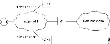
The following output is for the PX1 configuration:
!
version 11.3
no service password-encryption
service tcp-small-servers
!
hostname ExampleProxy
!
no ip domain-lookup
!
proxy h323
!
interface Ethernet0
 ip address 172.21.127.38 255.255.255.192
 no ip redirects
 ip rsvp bandwidth 7000 7000
 ip route-cache same-interface
 fair-queue 64 256 1000
 h323 interface
 h323 qos rsvp controlled-load
 h323 h323-id px1@zone1.com
 h323 gatekeeper ipaddr 172.21.127.39
!
interface Serial0
 no ip address
 shutdown
!
interface Serial1
 no ip address
 shutdown
!
router rip
 network 172.21.0.0
!
ip classless
!
line con 0
 exec-timeout 0 0
line aux 0
 transport input all
line vty 0 4
 password lab
 login
!
end
Closed Co-Edge Proxy with ASR Without Subnetting
The figure below shows how to configure RIP on the edge networks and IGRP on the two backbone networks. A Cisco 2500 router is used for the proxy.
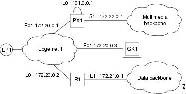
The following output is for the PX1 configuration:
!
version 11.3
no service password-encryption
service tcp-small-servers
!
hostname ExampleProxy
!
!
no ip domain-lookup
!
!
proxy h323
!
interface Loopback0
 ip address 10.0.0.1 255.0.0.0
 h323 interface
 h323 qos ip-precedence 4
 h323 h323-id px1@zone1.com
 h323 gatekeeper ipaddr 172.20.0.3
!
interface Ethernet0
 ip address 172.20.0.1 255.255.255.192
 no ip redirects
!
interface Serial0
 no ip address
 shutdown
!
interface Serial1
 ip address 172.22.0.1 255.255.0.0
 ip access-group 101 in
 ip access-group 101 out
 h323 asr
!
router rip
 network 172.20.0.0
 network 10.0.0.0
!
router igrp 4000
 network 172.22.0.0
 network 101.0.0.0
!
ip classless
access-list 101 permit ip any host 10.0.0.1
access-list 101 permit ip host 10.0.0.1 any
access-list 101 permit igrp any any
!
!
line con 0
 exec-timeout 0 0
line aux 0
 transport input all
line vty 0 4
 password lab
 login
Endpoints Example
Alternate Endpoints
The following example shows that an alternate endpoint has been configured. There are three carrier IDs (CARRIER_ABC, CARRIER_DEF, and CARRIER_GHI).
gatekeeper
 zone local GK cisco.com 172.16.32.12
 zone remote gk2 cisco.com 172.32.33.44 1719
 zone prefix gk2 414*
 gw-type-prefix 919*
 no shutdown
 endpoint alt-ep h323id gwid 1.1.1.1 carrier-id CARRIER_ABC
 endpoint alt-ep h323id gwid 1.1.1.1 carrier-id CARRIER_DEF
 endpoint alt-ep h323id gwid 2.2.2.2 carrier-id CARRIER_GHI
The following example shows that the endpoint at 172.16.53.15 1719 has been configured as an alternate for GW10. There are no carrier IDs:
endpoint alt-ep h323id
 GW10 172.16.53.15 1719
Nonavailability
The following example shows that the lrq reject-resource-low command has been configured on the gatekeeper:
gatekeeper
 lrq reject-resource-low
Endpoint-Based Call Capacity Management
The following example shows that the maximum number of calls that GW-1 can handle is 1000:
Router(config)# gatekeeper
Router(config-gk)# endpoint max-calls h323id GW-1 1000
The following example displays concurrent calls for the endpoint. In the first call example, "Voice Capacity Max.= 10000" means that the maximum calls for the endpoint are 10000. "Avail.= 10000" indicates that currently available calls for the endpoint are 10000. "Current.= 0" shows that current active calls for the endpoint are 0. (If the endpoint is not reporting capacity and the endpoint max-calls h323id command is not configured, "Voice Capacity Max." and "Avail." are shown as -1.)
Router# show gatekeeper endpoints
          GATEKEEPER ENDPOINT REGISTRATION
          ================================
CallSignalAddr  Port  RASSignalAddr   Port  Zone Name         Type    Flags
--------------  ----  -------------   ----  ---------         ----    -----
172.18.200.27   1720  172.18.200.27   57245 GK-1              VOIP-GW
    H323-ID:GW1
    Voice Capacity Max.= 10000  Avail.= 10000  Current.= 0
172.18.200.29    1720  172.18.200.29   58703 GK-2             VOIP-GW
    H323-ID:GW2
    Voice Capacity Max.= 23  Avail.= 23  Current.= 0
Total number of active registrations = 2
Endpoint Unregistration
The following example shows that all endpoints have been unregistered:
GATEKEEPER ENDPOINT REGISTRATION
                    ================================
CallSignalAddr  Port  RASSignalAddr   Port  Zone Name         Type    Flags
--------------- ----- --------------- ----- ---------         ----    -----
Total number of active registrations = 0
IRR Timer and Disable IRQ Requests Example
Sequential LRQ Enhancement Example
The following example shows a gatekeeper with the Sequential LRQ Enhancement feature enabled:
Router# show running-config
Building configuration...
Current configuration : 1802 bytes
!
version 12.2
.
.
.
gatekeeper
 zone local Zone1 cisco.com
 zone remote c3620-1-gk cisco.com 209.165.200.225 1719
 zone remote c2514-2-gk cisco.com 209.165.200.228 1719
 zone remote gk-cisco-mn cisco.com 209.165.200.230 1719
 zone remote gkzone3 cisco.com 209.165.200.235
 zone remote gk-catapult cisco.com 209.165.200.229 1719
 zone prefix gkzone3 405.......
 zone prefix gk-gk5 515....
 zone prefix c2514-2-gk 910.......
 zone prefix c3620-1-gk 917300....
 zone prefix c2514-2-gk 919.......
 zone prefix gk-cisco-mn 919.......
 zone prefix c3620-1-gk 919.......
 lrq reject-resource-low
 lrq lrj immediate-advance
 timer lrq window 6
 no shutdown
.
.
.
Additional References
Related Documents
| Related Topic |
Document Title |
||
|---|---|---|---|
| Cisco IOS Release 12.4 |
http://www.cisco.com/en/US/docs/ios/12_3/vvf_c/cisco_ios_voice_configuration_library_glossary/vcl.htm
|
||
| Cisco IOS Release 12.3 |
|
||
| Cisco IOS Release 12.2 |
http://www.cisco.com/en/US/docs/ios/12_2/voice/configuration/guide/fvvfax_c.html |
||
| Troubleshooting and Debugging guides |
http://www.cisco.com/en/US/docs/ios/debug/command/reference/db_book.html
http://www.cisco.com/en/US/docs/routers/access/1700/1750/software/configuration/guide/debug.html |
||
| Cisco Unified Border Element Configuration Examples |
|
||
| Related Application Guides |
http://www.cisco.com/en/US/products/sw/voicesw/ps556/products_programming_reference_guides_list.html
|
Standards
| Standards |
Title |
|---|---|
| ITU-T E.164 |
Overall network operation, telephone service, service operation and human factors |
| ITU-T H.225 Version 2 |
Call signalling protocols and media stream packetization for packet-based multimedia communication systems |
| ITU-T H.235 |
Security and encryption for H-Series (H.323 and other H.245-based) multimedia terminals |
| ITU-T H.323 |
Packet-based multimedia communications systems |
| ITU-T H.450 |
Supplementary services for multimedia |
MIBs
| MIBs |
MIBs Link |
|---|---|
|
To locate and download MIBs for selected platforms, Cisco IOS releases, and feature sets, use Cisco MIB Locator found at the following URL: http://www.cisco.com/go/mibs |
Cisco and the Cisco logo are trademarks or registered trademarks of Cisco and/or its affiliates in the U.S. and other countries. To view a list of Cisco trademarks, go to this URL: www.cisco.com/go/trademarks. Third-party trademarks mentioned are the property of their respective owners. The use of the word partner does not imply a partnership relationship between Cisco and any other company. (1110R)
Any Internet Protocol (IP) addresses and phone numbers used in this document are not intended to be actual addresses and phone numbers. Any examples, command display output, network topology diagrams, and other figures included in the document are shown for illustrative purposes only. Any use of actual IP addresses or phone numbers in illustrative content is unintentional and coincidental.
 Feedback
Contact Cisco
- Open a Support Case

- (Requires a Cisco Service Contract)
This Document Applies to These Products
- Collaboration Endpoints - Retired Products
- Conferencing - Retired Products
- Contact Center - Retired Products
- Optical Networking - Retired Products
- Routers - Retired Products
- Security - Retired Products
- Servers - Unified Computing (UCS) Retired Products
- Storage Networking Retired Products
- Switches - Retired Products
- Video - Retired Products
- Wireless - Retired Products