Overview
Available Languages
Table Of Contents
Understanding How the NAM Works
Understanding How the NAM Uses SPAN
Understanding How the NAM Uses VACLs
Understanding How the NAM Uses NDE
Monitoring 6500/7600 WAN Interfaces Through VACL
WAN Monitoring Through NetFlow Data Export (NDE) from Remote Routers and Switches
Multiple NAM Configuration Support
Online Documentation Enhancements
Overview
This chapter describes the Catalyst 6000 series switch NAM, how it operates, and how to manage it. This chapter includes these sections:
•
Understanding How the NAM Works
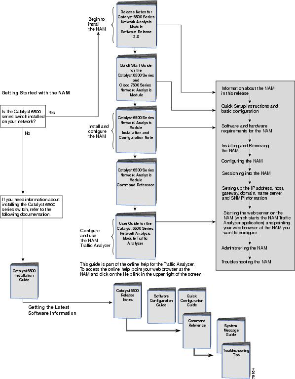
Before You Begin
To help you get started using the NAM, refer to this roadmap:
Understanding How the NAM Works
The NAM monitors and analyzes network traffic for the Catalyst 6500 series switches and Cisco 7600 series Internet Routers using remote monitoring (RMON), RMON extensions for switched networks (SMON), and other management information bases (MIBs). (See the "Supported MIB Objects" section on page 5-15.)
The NAM monitors, analyzes, and views NetFlow on remote devices and supports the following RMON groups:
•
•
The NAM also can monitor individual Ethernet VLANs, which allows it to serve as an extension to the basic RMON support provided by the Catalyst 6500 series, Cisco 7600 series, Catalyst 6000 family supervisor engine.
You can use any other IETF-compliant RMON application to access link, host, protocol, and response-time statistics for capacity planning, departmental accounting, and real-time application protocol monitoring. You also can use filters and capture buffers to troubleshoot the network.
The NAM can analyze Ethernet VLAN traffic from the following sources:
•
For more information about SPAN and RSPAN, refer to the "Configuring SPAN and RSPAN" chapter in the Catalyst 6500 Series Switch Software Configuration Guide.
•
•
•
For more information about NDE, refer to the Catalyst 6500 Series Switch Software Configuration Guide.
.
Understanding How the NAM Uses SPAN
The WS-SVC-NAM-1 platform provides a single destination port for SPAN sessions. The WS-SVC-NAM-2 platform provides two possible destination ports for SPAN and VACL sessions. Multiple SPAN sessions to the NAM are supported, but they must be destined for different ports. The NAM destination ports for use by the SPAN graphical user interface (GUI) are named DATA PORT 1 and DATA PORT 2 by default. In the CLI, SPAN ports are named as shown in Table 1-2.
Table 1-2 SPAN Port Names
data-port 1, data-port 2
For NAM-1 module number:3
For NAM-2 module number:7 or module number:8
Each of these ports is independent. You may create collections that are populated by only the traffic from one of the ports, or collections can be populated by traffic from both ports. You can still create VLAN-based collections, with packets from either port that match the specified VLAN populating such collections.
SPAN Session
A SPAN session is an association of a destination interface with a set of source interfaces; you configure SPAN sessions using parameters that specify the type of network traffic to monitor. SPAN sessions allow you to monitor traffic on one or more interfaces, or one or more VLANs, and send either ingress traffic, egress traffic, or both to a destination interface.
You can configure up to six separate SPAN sessions (two ingress, four egress) with separate or overlapping sets of SPAN source interfaces or VLANs. A bi-directional SPAN session counts as both one ingress and one egress session. Both switched and routed interfaces can be configured as SPAN sources.
SPAN sessions do not interfere with the normal operation of the switch. When enabled, a SPAN session might become active or inactive based on various events or actions; a syslog message indicates this. The show monitor session command displays the operational status of a SPAN session.
A SPAN session will remain inactive after system boot-up until the destination interface is operational.
Destination Interface
A destination interface (also called a monitor interface) is a switched or routed interface where SPAN sends packets for analysis. Once an interface becomes an active destination interface, incoming traffic is disabled. You cannot configure a SPAN destination interface to receive ingress traffic. The interface does not forward any traffic except that required for the SPAN session.
An interface specified as a destination interface in one SPAN session cannot be a destination interface for another SPAN session. An interface configured as a destination interface cannot be configured as a source interface. EtherChannel interfaces cannot be SPAN destination interfaces.
Specifying a trunk interface as a SPAN destination interface stops trunking on the interface.
Source Interface
A source interface is an interface monitored for network traffic analysis. One or more source interfaces can be monitored in a single SPAN session with user-specified traffic types (ingress, egress, or both) applicable for all the source interfaces. All sources for a particular SPAN session are spanned in the same direction.
You can configure source interfaces for any VLAN. You can configure VLANs as source interfaces, which means that all interfaces in the specified VLANs are source interfaces for the SPAN session. Trunk interfaces can be configured as source interfaces and can be mixed with nontrunk source interfaces; however, the destination interface never encapsulates, so you do not see any encapsulation out of the SPAN destination interface.
Traffic Types
Ingress SPAN (Rx) copies network traffic received by the source interfaces for analysis at the destination interface. Egress SPAN (Tx) copies network traffic transmitted from the source interfaces. Specifying the configuration option "both" copies network traffic received and transmitted by the source interfaces to the destination interface.
VLAN-Based SPAN
VLAN-based SPAN analyzes the network traffic in one or more VLANs. You can configure VLAN based-SPAN as ingress SPAN, egress SPAN, or both. All of the interfaces in the source VLANs become source interfaces for the VLAN-based SPAN session.
Use the following guidelines for VLAN-based SPAN sessions:
•
•
•
•
•
SPAN Traffic
All network traffic, including multicast and bridge protocol data unit (BPDU) packets, can be monitored using SPAN.
In some SPAN configurations, multiple copies of the same source packet are sent to the SPAN destination interface. For example, a bidirectional (both ingress and egress) SPAN session is configured for sources a1 and a2 to a destination interface d1. If a packet enters the switch through a1 and gets switched to a2, both incoming and outgoing packets are sent to destination interface d1; both packets would be the same (unless a Layer-3 rewrite had occurred, in which case the packets would be different).
Understanding How the NAM Uses VACLs
VACL is a way to forward traffic from either a WAN interface or VLANs to a data port on the NAM. This feature provides an alternative to using SPAN for similar purposes. The VACL data analysis capability is not supported for the WS-X6380-NAM.
There are two types of VACLs, one which captures all bridged or routed VLAN packets and another which captures a selected subset of all bridged or routed VLAN packets. Catalyst operating system VACLs can only be used to capture VLAN packets because they are initially routed or bridged into the VLAN on the switch.
VACLs can provide access control for all packets that are bridged within a VLAN or that are routed into or out of a VLAN or, with releases 12.1(13)E or later, a WAN interface. Unlike regular Cisco IOS standard or extended ACLs that are configured on router interfaces only and are applied on routed packets only, VACLs apply to all packets and can be applied to any VLAN or WAN interface. VACLS are processed in hardware.
VACLs use Cisco IOS ACLs. VACLs ignore any Cisco IOS ACL fields that are not supported in hardware. Standard and extended Cisco IOS ACLs are used to classify packets. Classified packets can be subject to a number of features such as access control (security), encryption, policy-based routing, and so on. Standard and extended Cisco IOS ACLs are only configured on router interfaces and applied on routed packets.
Once a VACL is configured on a VLAN, all packets (routed or bridged) entering the VLAN are checked against the VACL. Packets can either enter the VLAN through a switch port or through a router port after being routed. Unlike Cisco IOS ACLs, VACLs are not defined by direction (input or output).
A VACL contains an ordered list of access control entries (ACEs). Each ACE contains a number of fields that are matched against the contents of a packet. Each field can have an associated bit mask to indicate which bits are relevant. An action is associated with each ACE that describes what the system should do with the packet when a match occurs. The action is feature dependent. Catalyst 6500 family switches support three types of ACEs in the hardware: IP, IPX, and MAC-Layer traffic. VACLs applied to WAN interfaces support only IP traffic. VACLs can provide access control based on Layer 3 addresses for IP and IPX protocols. Unsupported protocols are access controlled through MAC addresses. MAC VACLs cannot be used to access control IP or IPX addresses.
When you configure a VACL and apply it to a VLAN, all packets entering the VLAN are checked against this VACL. If you apply a VACL to the VLAN and an ACL to a routed interface in the VLAN, a packet coming in to the VLAN is first checked against the VACL and, if permitted, is then checked against the input ACL before it is handled by the routed interface. When the packet is routed to another VLAN, it is first checked against the output ACL applied to the routed interface and, if permitted, the VACL configured for the destination VLAN is applied. If a VACL is configured for a packet type and a packet of that type does not match the VACL, the default action is deny.
When configuring VACLs the following apply:
•
•
•
For details on how to configure VACL with Cisco IOS software, refer to the Network Analysis Module for Catalyst 6500 Series and Cisco 7600 Series Command Reference. For details on how to configure security ACLs with the Catalyst operating system, refer to the Catalyst 6500 Series Software Configuration Guide and the Catalyst 6500 Series Command Reference.
Understanding How the NAM Uses NDE
To use a remote device as an NDE data source for the NAM, you must configure the remote device itself to export NDE packets to UDP port 3000 on the NAM. You may need to configure the device itself on a per-interface basis. A screen has been added to the web application UI for specifying NDE devices An NDE device is identified by its IP address. By default the switch's local supervisor engine always is available as an NDE device.
You then can define additional NDE devices by specifying the IP addresses and (optionally) the community strings. Community strings are used to upload convenient textual strings for interfaces on the remote devices that are monitored in NetFlow records.
Distinguishing among different interfaces on the remote NDE devices is a feature in this release that allows you to arbitrarily bundle groups of interfaces on each remote NDE device into a conceptual data source rather than simply grouping all flows into the same collections.
If you tried to distinguish every single interface on every remote device (potentially in both directions separately) it is possible this action could result in a large, unmanageable number of data sources. By using conceptual data sources you are given complete flexibility to group all interfaces in all directions into one single conceptual data source.
You may also choose to create a separate conceptual data source for each interface on the device. In general, you can combine any number of "simple flow paths" together to form a conceptual data source. Each simple flow path may consist of a single interface in the input direction, the output direction, or both directions.
The following restrictions apply when creating conceptual data sources and assigning flow paths to them:
•
•
•
Managing the NAM
The NAM is managed and controlled from the embedded web-based NAM Traffic Analyzer application (directing a web browser to the NAM) or a Simple Network Management Protocol (SNMP) management application, such as those bundled with CiscoWorks, or both.
The NAM Traffic Analyzer application provides access to the management features and monitoring features for NAM data and voice traffic through a web browser. To use the NAM Traffic Analyzer application, you first need to do some basic configuration tasks on the NAM using the CLI. You then can start the NAM Traffic Analyzer application with a single command.
With NAM Traffic Analyzer, you can do the following tasks:
•
•
•
•
•
•
For added security, you can use the NAM Traffic Analyzer application to configure the NAM to use a remote TACACS+ server. A TACACS+ server can be used for authentication and authorization for your web-based users. You also can use a local database on the NAM for security.
You also can manage the NAM using an SNMP management application such as the Cisco NetScout nGenius Real-Time Monitor (RTM). For more information about using RTM, refer to the CiscoWorks documentation or refer to this URL:
http://www.Cisco.com/univercd/cc/td/doc/product/lan/cat6000/fam_mod/rel2_1_2/ol_2428.htm
To use RMON and SNMP agent support, you configure the NAM using the CLI.
If you have a NAM that is already configured and running in the switch, and you are familiar with the NAM, you can begin using the NAM Traffic Analyzer application by entering the ip http server enable CLI command and then starting NAM Traffic Analyzer in your browser.
Refer to the User Guide for the Network Analysis Module Traffic Analyzer Relaeas 3.1 for more information about using the NAM Traffic Analyzer application.
New NAM Features
These are the new features for the NAM platforms in software release 3.1:
Monitoring 6500/7600 WAN Interfaces Through VACL
VACL is used as a means of sourcing packets to the NAM for monitoring. VACL (VLAN Access Control Lists) capture support is now available for WAN cards on the NAM-1 and NAM-2. NetFlow also provides some information on the WAN traffic. The NAM utilizes these data sources to provide application level visibility into WAN traffic as follows:
•
•
•
WAN Monitoring Through NetFlow Data Export (NDE) from Remote Routers and Switches
The NAM can now accept NDE packets, specially formatted packets generated by routers and switches that summarize traffic levels for flows that have passed through the device, from external devices in addition to the local supervisor engine and has the ability to distinguish traffic on different interfaces of the NDE sources and monitor them as separate data sources.
•
•
•
•
•
•
Historical Reporting
This feature provides three types of reports:
•
•
•
VLAN Traffic Statistics
•
•
•
•
Multiple NAM Configuration Support
•
•
•
Online Documentation Enhancements
•
•
Front Panel Description
The NAM front panel (see Figure 1-1) includes a STATUS LED and SHUTDOWN button.
Figure 1-1 Network Analysis Module

STATUS LED
The STATUS LED indicates the operating states of the NAM. Table 1-3 describes the LED operation.
SHUTDOWN Button

Caution
To avoid corrupting the NAM hard disk, you must correctly shut down the NAM before you remove it from the chassis or disconnect the power. This shutdown procedure is normally initiated by commands entered at the supervisor engine CLI prompt or the NAM CLI prompt.
If the NAM fails to respond to these commands properly, press the SHUTDOWN button on the front panel to initiate the shutdown procedure.
The shutdown procedure may require several minutes. The STATUS LED turns off when the NAM shuts down.
Specifications
Table 1-4 describes the specifications for the NAM.
 Feedback
Contact Cisco
- Open a Support Case

- (Requires a Cisco Service Contract)
This Document Applies to These Products
- Collaboration Endpoints - Retired Products
- Conferencing - Retired Products
- Contact Center - Retired Products
- Optical Networking - Retired Products
- Routers - Retired Products
- Security - Retired Products
- Servers - Unified Computing (UCS) Retired Products
- Storage Networking Retired Products
- Switches - Retired Products
- Video - Retired Products
- Wireless - Retired Products