
New and changed information
The following table provides an overview of the significant changes up to this current release. The table does not provide an exhaustive list of all changes or of the new features up to this release.
| Release Version | Feature | Description |
|---|---|---|
|
Nexus Dashboard 4.2.1 |
Fabric designer in Nexus Dashboard |
With this release, Nexus Dashboard introduces the Fabric Designer feature, enabling you to virtually plan and design your network fabric before you purchase or deploy any physical equipment. |
Overview
The fabric designer feature in Nexus Dashboard allows you to plan and design your network fabric virtually before purchasing any physical equipment. You can create a virtual representation of your network topology, which streamlines the design and pre-provisioning process. This approach enables you to accurately plan physical components, cabling, and network configurations, reducing errors and ensuring seamless deployment when the physical devices arrive.
You can add any combination of spine, leaf, and border switches to your fabric. Nexus Dashboard automatically configures vPC peer links with built-in checks, simplifying the vPC setup. It also auto-generates topology views and guides you in connecting switches, making cabling setup easier and more accurate.

The fabric designer feature supports iBGP and eBGP variants for the Data Center VXLAN fabric type only.
Guidelines and Limitations
-
Fabric designer is primarily intended for initial network setup and as a planning or sales tool. You can only enable the fabric designer when you create a new fabric. You cannot enable the fabric designer later through the edit fabric action. For detailed verified scalability guidelines, see Cisco Nexus Dashboard Verified Scalability Guide. These guidelines also apply to fabric designs.
-
When you enable the fabric designer option for a fabric, Nexus Dashboard disables manual pre-provisioning of other devices to prevent unsupported configurations and unexpected behavior.
-
When you modify a fabric design, Nexus Dashboard deletes the existing pre-provisioned switches, interfaces, and links, and then re-creates them based on the updated design parameters.
-
Only IPv4 addresses are supported for pre-provisioned devices. IPv6 addresses and custom subnet ranges are not supported.
-
After the fabric is moved from design mode to production mode, you cannot revert it back to design mode.
Create or onboard a fabric with fabric designer
Follow these steps to create fabric with fabric designer.
-
Navigate to the Fabrics page.
Go to Manage > Fabrics.
-
Click the Fabrics tab.
-
From the Actions drop-down list, choose Create fabric.
The Create/Onboard Fabric page displays.
-
Under Select a category, choose Create new LAN fabric and click Next.
-
Under Select a type, click VXLAN and choose Data Center VXLAN EVPN.
-
Click Next.
-
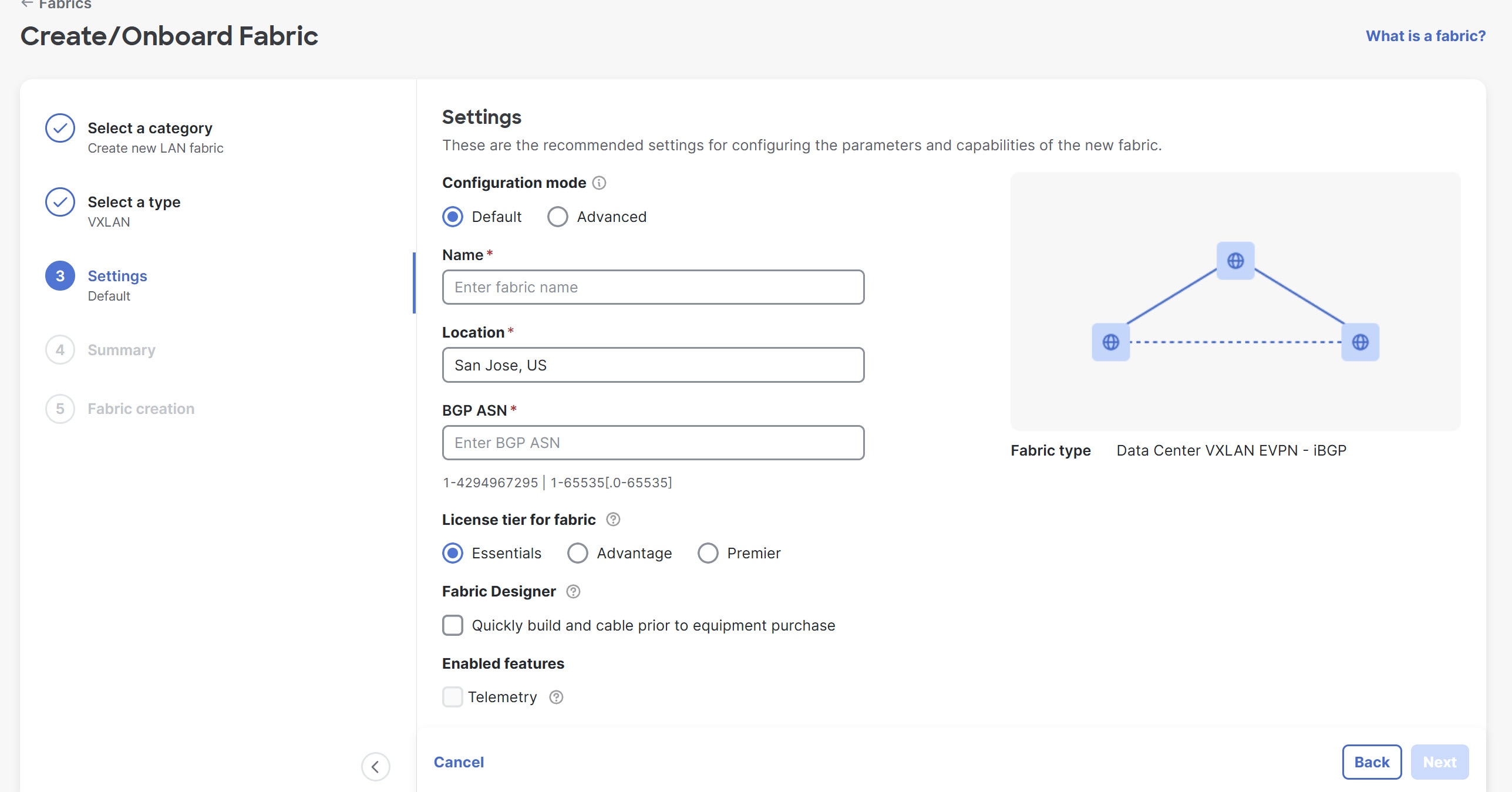
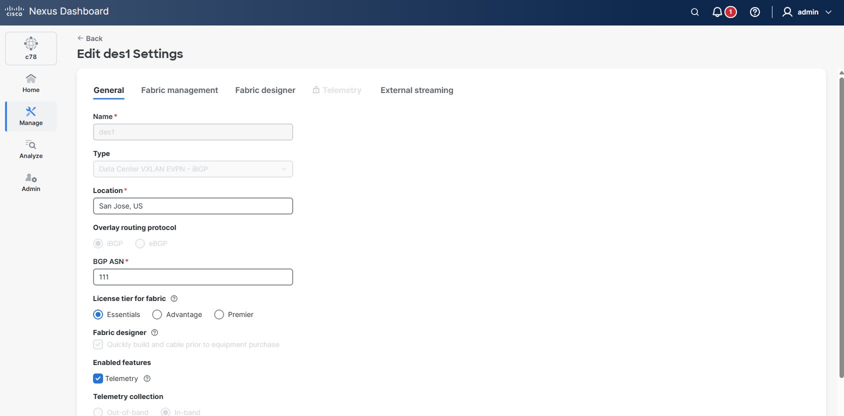
Under Settings, configure the fabric settings.
Field Description Configuration mode
Determine which type of configuration mode that you want to use to configure this fabric. You can choose one of the following options.
-
Default
-
Advanced
Name
Provide a unique name for the fabric.
Location
Choose the location for the fabric.
BGP ASN
Enter the BGP autonomous system number (ASN) for the fabric’s spine switches. The following are the valid entries.
1-4294967295 | 1-65535[.0-65535]where:
-
1-4294967295denotes an integer (whole) value from 1 to 4294967295 (inclusive), or -
1-65535[.0-65535]denotes a decimal value, where the left side of the decimal is a number from 1 to 65535 (inclusive) and the right side of the decimal is a value from 0 to 65535 (inclusive).
Following are examples of valid entries that would fall into either category above:
-
1 -
31 -
7654321 -
1.1 -
1.65535 -
2.999 -
65535.1
Following are examples of invalid entries that would violate the guidelines shown above:
-
-5 -
1.300000 -
65536.1
License tier for fabric
Choose the licensing tier for the fabric.
-
Essentials
-
Advantage
-
Premier
Click the information icon (?) next to License tier to see what functionality is enabled for each license tier.
Fabric designer
This option allows you to design and build your fabric before purchasing the equipment. To enable Fabric Designer option, check the Quickly build a cable prior to equipment purchase check box.
Once you check the Quickly build a cable prior to equipment purchase check box, the Fabric designer settings option appears in the left navigation pane. Note that the Fabric designer option is applicable only for data center VXLAN EVPN fabrics.
The Fabric designer settings option appears after the Settings step in the left navigation pane, when you choose the Default configuration mode. If you choose Advanced configuration mode, this option appears after Advanced settings step.
Enabled features
Enabling the Fabric designer option automatically disables the Telemetry check box.
Fabric designer does not support telemetry.
-
-
Click Next.
-
If you chose Default configuration mode, the next step in the Create/Onboard Fabric workflow is to configure Fabric designer settings. For more information, see Configure fabric designer settings.
-
If you chose Advanced configuration mode, the next step in the Create/Onboard Fabric workflow is Advanced settings. For more information, see the "Advanced settings" section in Creating LAN and ACI Fabrics and Fabric Groups.
-
Configure fabric designer settings
After enabling the Quickly build a cable prior to equipment purchase option, proceed to the Fabric designer settings section to define your desired fabric architecture and specify device models for your network topology.
Follow these steps to configure fabric designer settings.
-
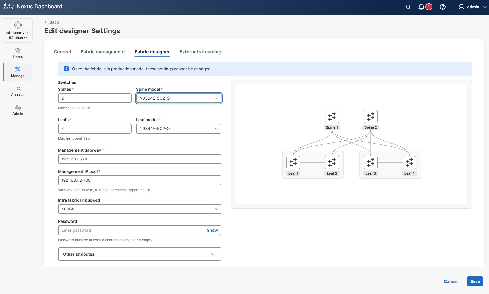
Under Fabric designer settings, configure the fabric architecture and device models for your network topology.
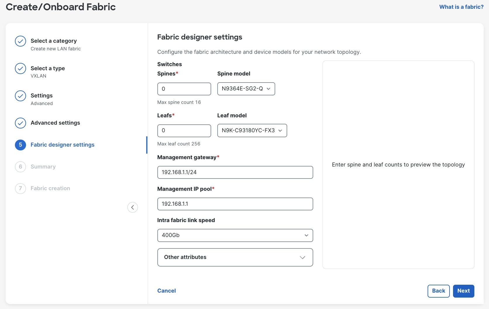
Configure the following parameters.
Field Description Spines
Provide the number of spine switches.
Spine model
Choose the desired model for your spine switches.
Leafs
Provide the number of leaf switches.
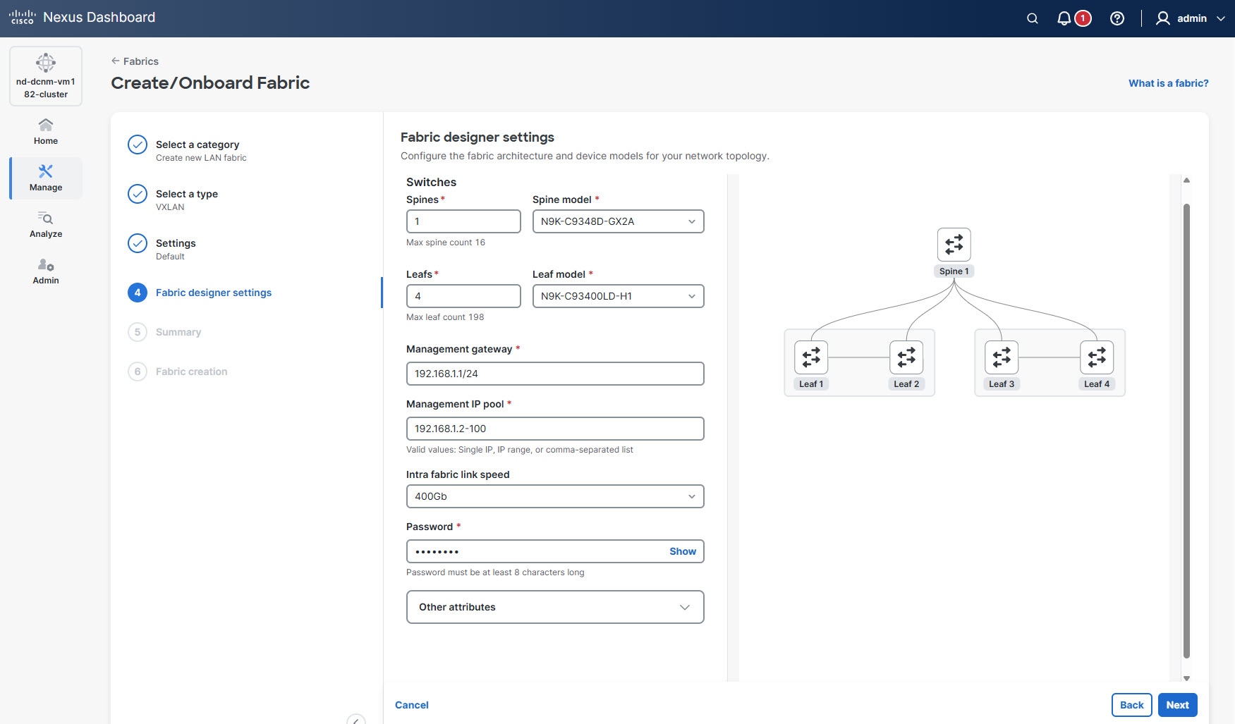
As you provide the spine and leaf counts, a visual preview of fabric topology appears on the right side of the page.
Leaf model
Choose the desired model for your leaf switches.
Management gateway
Enter the IP address of the gateway used for managing your network devices.
Management IP pool
Specify the range of IP addresses to be allocated for management interfaces of the switches.
Intra fabric link speed
Choose the speed for connections between spine and leaf switches.
Password
Set a password for device access and configuration.
Other attributes
Add any additional attributes or custom settings relevant to your network deployment.
For more information, see Configure other attributes.
If the configuration is non-viable (for example, insufficient ports for requested link capacity or unsupported model), Nexus Dashboard provides real time feedback and reasons.
-
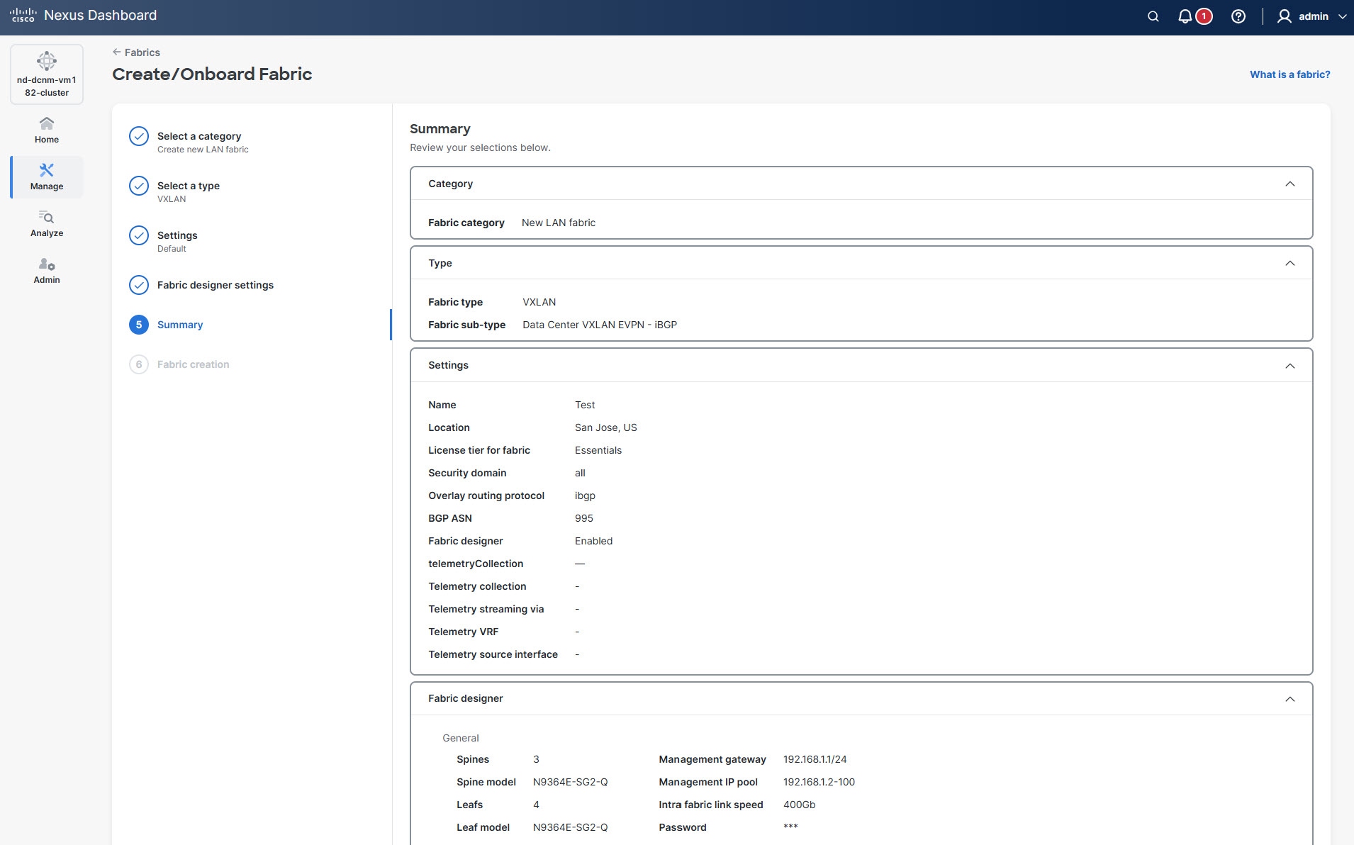
Click Next.
The Summary page displays
-
Verify all of the information that is shown in the Summary page is correct.
-
Click Submit.
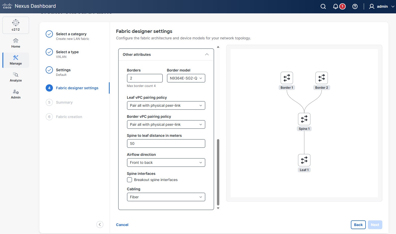
Configure other attributes
You can define additional attributes and custom settings relevant to your network deployment.
Follow these steps to configure the additional attributes.
-
Click the arrow in the Other attributes field to expand the section.
The following attributes display.
-
Provide the necessary details for each field.
Field Description Borders
Specify the number of border devices in the network design. The value is set to 0, by default.
You can configure a maximum of 4 border devices.
Border model
Allows you to choose a specific model or type for the border devices.
Leaf vPC pairing policy
Allows you to define how vPC pairings are handled for leaf switches. Choose one of the following options.
-
Pair all with physical peer-link — indicates that this option configures all leaf vPCs to use a physical peer-link. This is the default and recommended option.
-
Pair over fabric link — indicates that this option configures all leaf vPCs to use the existing network fabric links.
-
None — indicates that this option does not configure any vPC pairing for the leaf switches.
Border vPC pairing policy
Allows you to define how vPC pairings are handled for border switches. Choose one of the following options.
-
Pair all with physical peer-link — indicates that this option configures all border vPCs to use a physical peer-link. This is the default and recommended option.
-
Pair over fabric link — indicates that this option configures all border vPCs to use the existing network fabric links.
-
None — indicates that this option does not configure any vPC pairing for the border switches.
Spine to leaf distance in meters
Specifies the physical distance (in meters) between the spine and leaf switches in the network fabric. The default value is 50 meters.
Airflow direction
Specifies the direction of airflow for the network equipment. Proper airflow management is essential for efficient cooling and maintaining optimal operating temperatures. By default, it is set to Front to back.
Some devices support only certain airflow directions. For example, the N9364E-SG2-Q has air intake only on the port side.
Spine interfaces
Check the Breakout spine interfaces check box to break out a high-speed spine port into multiple lower-speed interfaces that match the chosen intra-fabric link speed, where applicable.
Cabling
Allows you to choose the type of cabling used for network connections. By default, Fiber cable type is chosen.
-
Edit designer fabric
Follow these steps to edit your designer fabric.
-
Navigate to the Fabrics page.
Go to Manage > Fabrics.
-
Choose the designer fabric that you want to edit.
-
From the Actions drop-down list, choose Edit fabric settings.
The Edit fabric-name settings page displays.
You can also access the Edit fabric-name settings page for a fabric from the Fabric Overview page. In the Fabric Overview page, click the Actions drop-down list and choose Edit fabric settings.
-
In the Edit fabric-name settings page, click the Fabric designer tab.
The Fabric designer tab is visible only for fabrics in the designer phase. Once you set a fabric to production mode, this tab no longer appears.
-
Update the required settings as needed.
As you update the border, spine and leaf counts, a visual preview of fabric topology appears on the right side of the page.
-
Click Save.
When you edit the parameters of a designer fabric, Nexus Dashboard removes all existing switches, interfaces, links, and their associated policies in the fabric before it re-generates the design based on the new set of parameters.
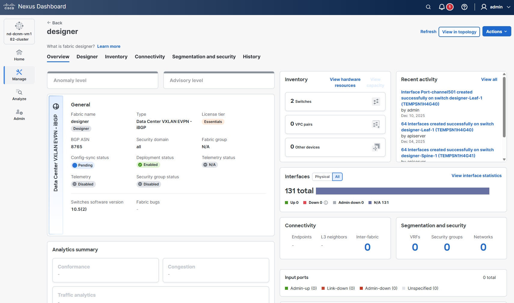
View and validate designer fabric details
Follow these steps to view and validate designer fabric details.
-
Navigate to the Fabrics page.
Go to Manage > Fabrics.
-
Click the designer fabric.
The Fabric Overview page displays.
-
Click the Designer tab.
The Designer tab appears only for the designer fabrics
Under the Designer tab, you can review and download the following options for your designer fabric.
You can see these options.
-
Assembly — Details on the fabric’s assembly components.
-
Cabling — Information on cabling layouts and requirements.
-
Configurations — Review available configuration options for the designer fabric.
-
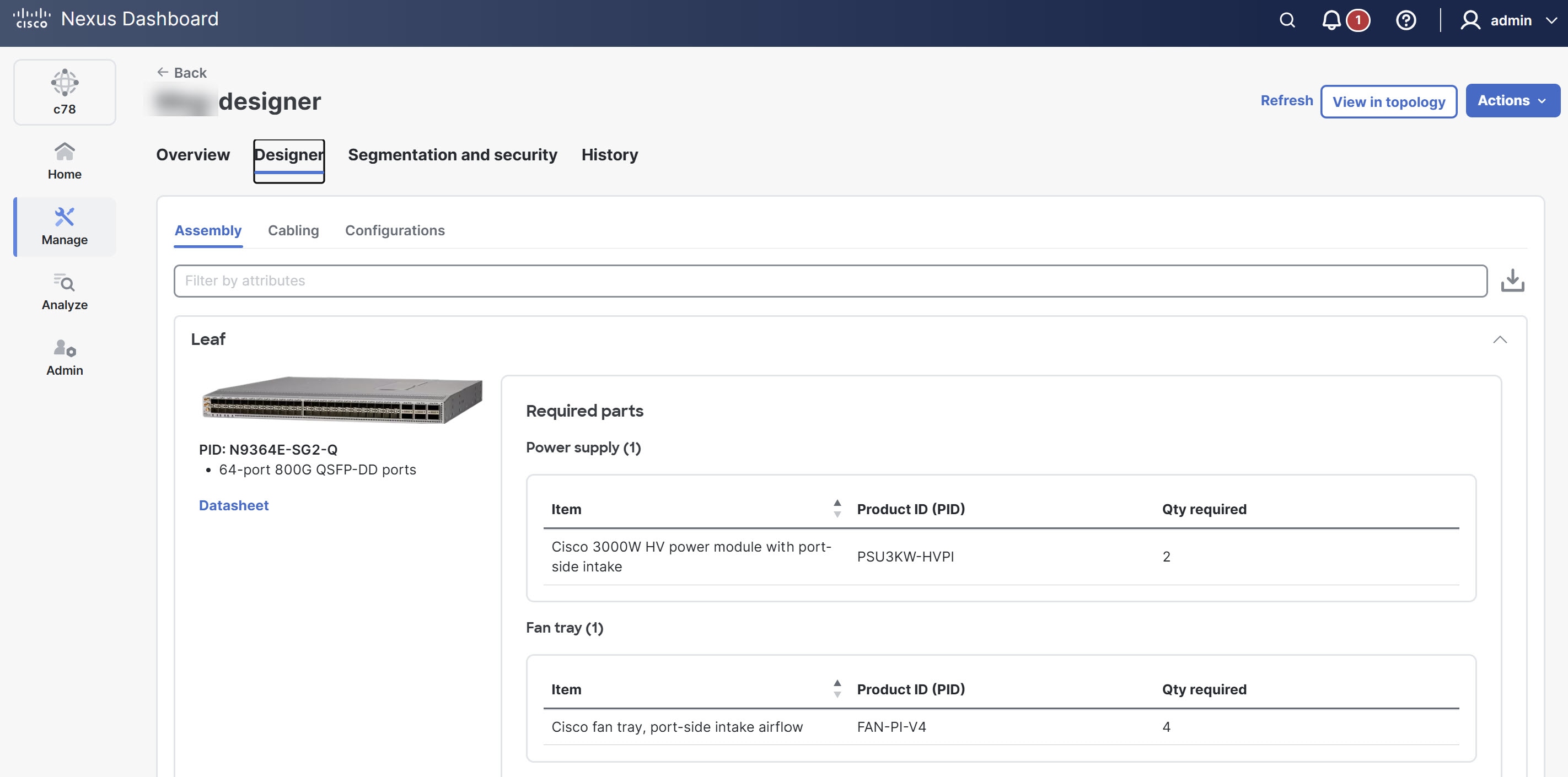
Review and download assembly details
Follow these steps to review and download assembly information for a designer fabric.
-
Navigate to the Designer tab.
-
Click Assembly.
You can view the information about the fabric’s components, structure, and layout.
-
Click the download icon (located on the right side of the Assembly section) to download a PDF file containing detailed assembly information for the designer fabric.
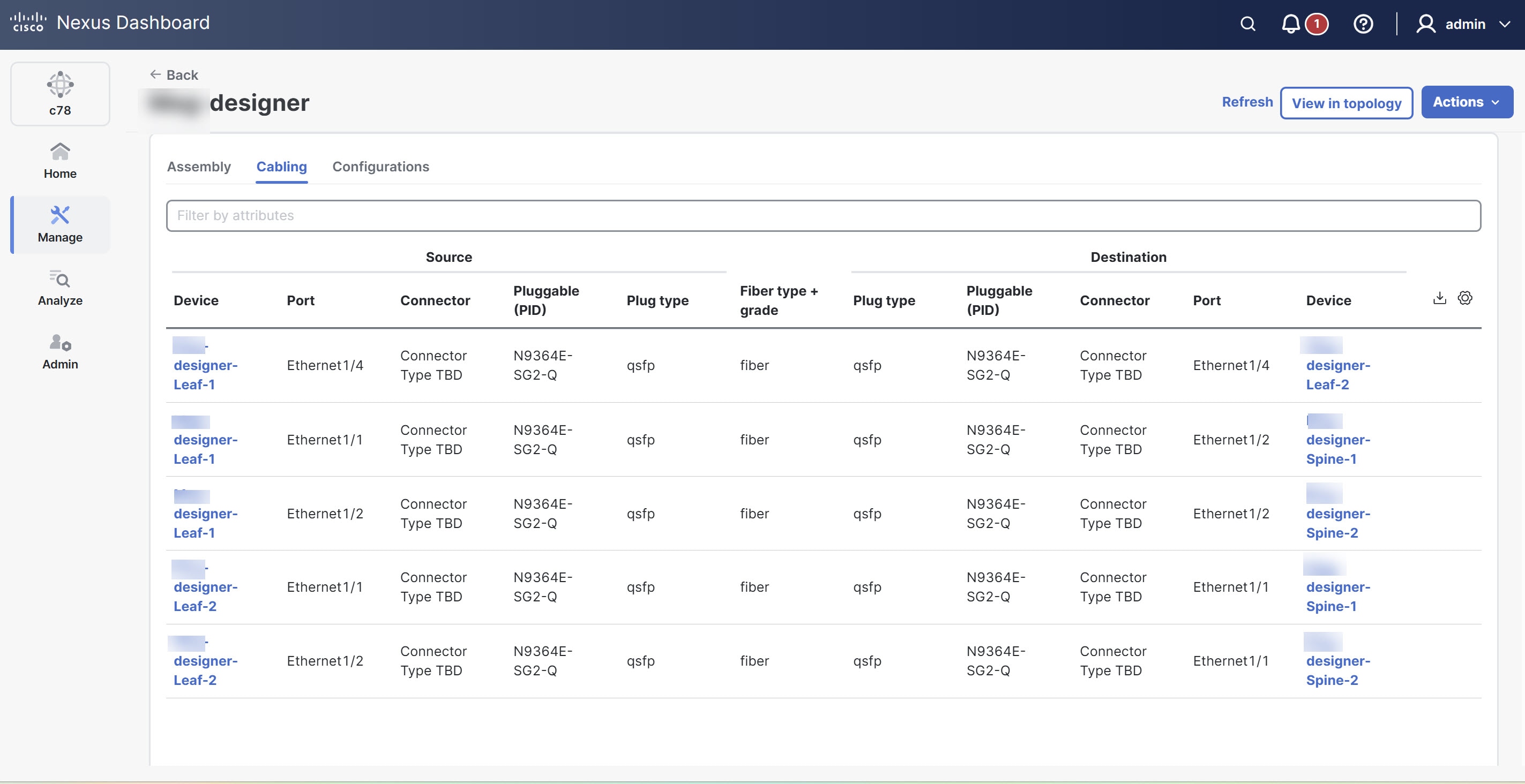
Review and download cabling details
Follow these steps to review and download cabling information for a designer fabric.
-
Navigate to the Designer tab.
-
Click Cabling.
The cabling details include information such as source and destination devices, ports, connector types, plug types, and fiber types used within the network fabric.
-
Click the download icon (located on the right side of the Cabling section) to download a CSV file containing detailed cabling information for the designer fabric.
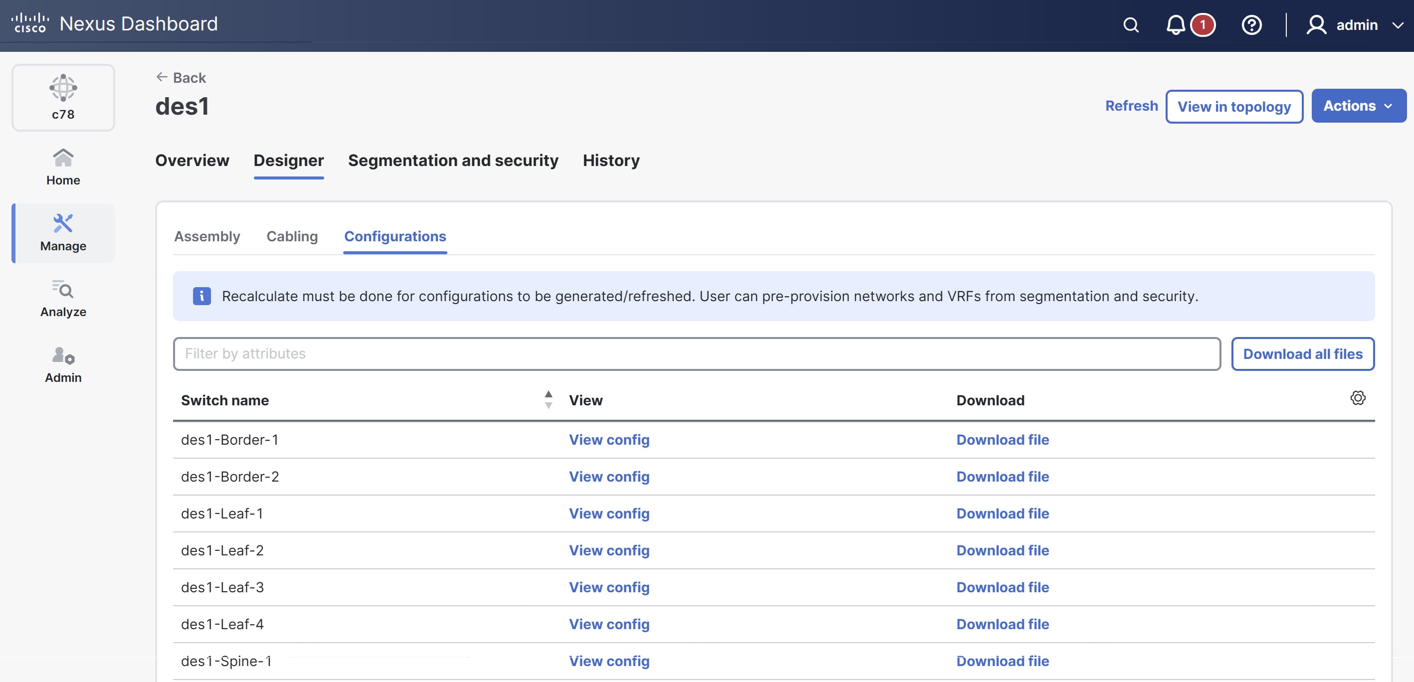
Review and download configuration details
Follow these steps to review and download configuration details for a designer fabric.
-
Navigate to the Designer tab.
-
Click Configurations.
The Config text dialog box opens which displays detailed switch information and configuration settings.
-
Click Download file next to the desired switch.
The Download fabric details dialog box opens. Click the Download button to download the congig.txt file containing configuration details of the switch.
-
Click the Download icon (located on the right side of the Configurations section) to download configuration details for all switches in the designer fabric. This allows you to download a ZIP file that contains detailed configuration information for the entire designer fabric.
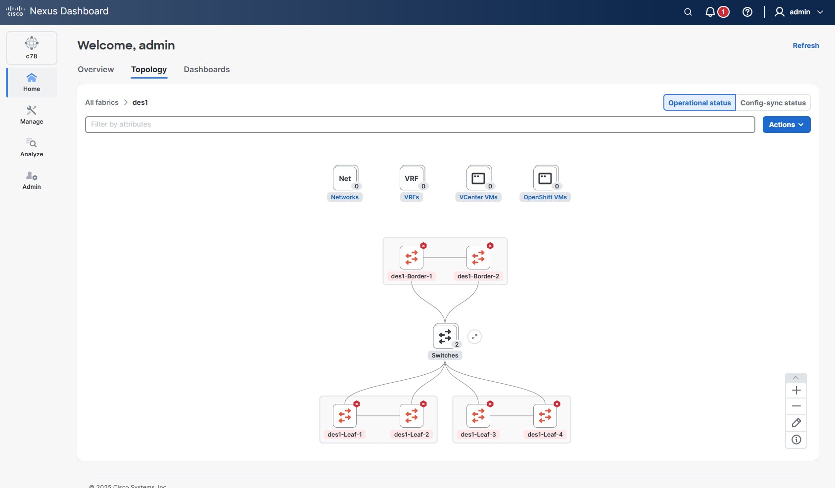
View designer fabric topology
After you create the designer fabric, you can view the design in the topology view of Nexus Dashboard. This view displays a graphical representation of your planned network and enables you to review switch placements, connections, and the overall fabric layout before deployment.
Follow these steps to view the topology of the designer fabric.
-
Navigate to the Fabrics page.
Go to Manage > Fabrics.
-
Click the designer fabric for which you want to view topology.
The Fabric Overview page displays.
-
Click the View in topology button.
The Topology page opens which displays the topology view of the designer fabric including switch placements, device connections, fabric layout and hierarchy.
Download fabric details
After you have created, defined, and validated your designer fabric, you can download the associated fabric assets.
Follow these steps to download the fabric assets.
-
Navigate to the Fabrics page.
Go to Manage > Fabrics.
-
Click the designer fabric for which you wish to download assets.
The Fabric Overview page displays.
-
From the Actions drop-down list, choose Designer > Download fabric details.
The Download files dialog box opens showing the list of assembly, cable, and configuration details.
-
Click Download all to download all available asset files.
To access the previous downloads, go to History > Specifications from the Fabric Overview page.
Modify designer fabric configuration
You can update interfaces, links, networks, or virtual routing and forwarding instances (VRFs) of the designer fabric under the Connectivity tab and Segmentation and Security tab for the designer fabric.
Follow these steps to modify the designer fabric.
-
Navigate to the Fabrics page.
Go to Manage > Fabrics.
-
Click the designer fabric you wish to update.
The Fabric Overview page displays.
-
Navigate to the Connectivity tab or the Segmentation and Security tab for your designer fabric to update the configuration as needed.
Verify inventory
After modifying your designer fabric, it is important to verify that all switches and vPC virtual port channel pairs are correctly configured and present in the system inventory. This ensures that your network infrastructure is accurately reflected in the management interface and helps identify any discrepancies or issues.
Follow these steps to verify the inventory.
-
Navigate to the Inventory page.
Go to Manage > Inventory.
The Inventory page displays a comprehensive list of all devices and components managed within your Nexus Dashboard.
-
Locate the switches and vPC pairs associated with your specific designer fabric.
-
Review the list of switches to ensure all expected devices are present.
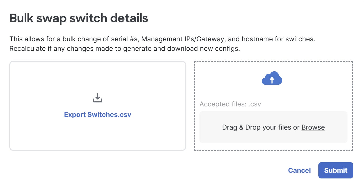
Bulk swap switch details
The bulk swap switch details feature enables you to efficiently update multiple switch configurations at once as you move the designer fabric to production mode. You can update the serial numbers when actual device serial numbers become available, assign production management IP addresses, and modify hostnames if you prefer alternatives to the default <fabricName>-<role>-<count> naming convention. The bulk swap process does not support gateway changes. After making these modifications, Nexus Dashboard automatically recalculates and generates new configuration files and then makes them available for you to download.
When you use the bulk swap feature, you cannot change certain fields, such as Model, vPC parameters, and Serial Number. However, you can edit the Requested Serial Number, Name, and IP Address fields.
Follow these steps to bulk swap serial numbers.
-
Navigate to the Fabrics page.
Go to Manage > Fabrics.
-
Click the designer fabric.
The Fabric Overview page displays.
-
From the Actions drop-down list, choose Designer > Bulk swap switch details.
The Bulk swap switch details dialog box opens.
-
You can either export the current switch details as a CSV file for reference or editing or upload your own CSV file containing the updated switch details.
-
Click Submit.
If you changed any information other than the switch serial numbers, recalculate again and download the new configuration files to deploy to the switches as needed.
Move to production mode
After you verify all configuration details and are confident that your designer fabric is ready for deployment, you can transition it to production mode. Moving a fabric to production mode is a critical step, as it finalizes the design and prepares the fabric for operational use. Note that after this transition, further design modifications are not permitted.
Follow these steps to move the fabric to production mode.
-
Navigate to the Fabrics page.
Go to Manage > Fabrics.
-
Click the designer fabric.
The Fabric Overview page displays.
-
From the Actions drop-down list, choose Designer > Production mode.
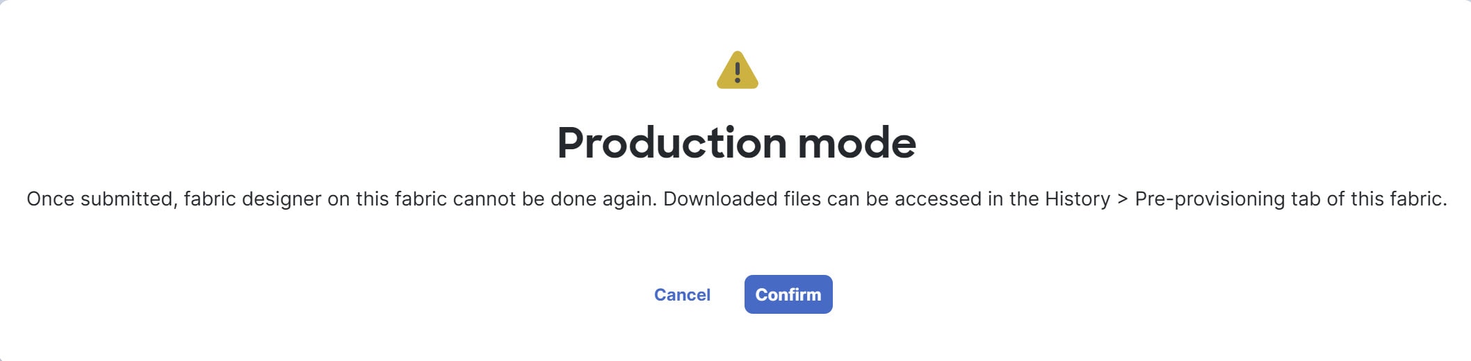
The Production mode dialog box opens.
-
Click Confirm to transition the designer fabric to production mode.
Once you submit the designer fabric to production mode, you cannot make further design changes to this fabric. However, you can still access previously generated downloads by navigating to History > Pre-provisioning within the Fabric Overview page.
Copyright
THE SPECIFICATIONS AND INFORMATION REGARDING THE PRODUCTS IN THIS MANUAL ARE SUBJECT TO CHANGE WITHOUT NOTICE. ALL STATEMENTS, INFORMATION, AND RECOMMENDATIONS IN THIS MANUAL ARE BELIEVED TO BE ACCURATE BUT ARE PRESENTED WITHOUT WARRANTY OF ANY KIND, EXPRESS OR IMPLIED. USERS MUST TAKE FULL RESPONSIBILITY FOR THEIR APPLICATION OF ANY PRODUCTS.
THE SOFTWARE LICENSE AND LIMITED WARRANTY FOR THE ACCOMPANYING PRODUCT ARE SET FORTH IN THE INFORMATION PACKET THAT SHIPPED WITH THE PRODUCT AND ARE INCORPORATED HEREIN BY THIS REFERENCE. IF YOU ARE UNABLE TO LOCATE THE SOFTWARE LICENSE OR LIMITED WARRANTY, CONTACT YOUR CISCO REPRESENTATIVE FOR A COPY.
The Cisco implementation of TCP header compression is an adaptation of a program developed by the University of California, Berkeley (UCB) as part of UCB’s public domain version of the UNIX operating system. All rights reserved. Copyright © 1981, Regents of the University of California.
NOTWITHSTANDING ANY OTHER WARRANTY HEREIN, ALL DOCUMENT FILES AND SOFTWARE OF THESE SUPPLIERS ARE PROVIDED “AS IS" WITH ALL FAULTS. CISCO AND THE ABOVE-NAMED SUPPLIERS DISCLAIM ALL WARRANTIES, EXPRESSED OR IMPLIED, INCLUDING, WITHOUT LIMITATION, THOSE OF MERCHANTABILITY, FITNESS FOR A PARTICULAR PURPOSE AND NONINFRINGEMENT OR ARISING FROM A COURSE OF DEALING, USAGE, OR TRADE PRACTICE.
IN NO EVENT SHALL CISCO OR ITS SUPPLIERS BE LIABLE FOR ANY INDIRECT, SPECIAL, CONSEQUENTIAL, OR INCIDENTAL DAMAGES, INCLUDING, WITHOUT LIMITATION, LOST PROFITS OR LOSS OR DAMAGE TO DATA ARISING OUT OF THE USE OR INABILITY TO USE THIS MANUAL, EVEN IF CISCO OR ITS SUPPLIERS HAVE BEEN ADVISED OF THE POSSIBILITY OF SUCH DAMAGES.
Any Internet Protocol (IP) addresses and phone numbers used in this document are not intended to be actual addresses and phone numbers. Any examples, command display output, network topology diagrams, and other figures included in the document are shown for illustrative purposes only. Any use of actual IP addresses or phone numbers in illustrative content is unintentional and coincidental.
The documentation set for this product strives to use bias-free language. For the purposes of this documentation set, bias-free is defined as language that does not imply discrimination based on age, disability, gender, racial identity, ethnic identity, sexual orientation, socioeconomic status, and intersectionality. Exceptions may be present in the documentation due to language that is hardcoded in the user interfaces of the product software, language used based on RFP documentation, or language that is used by a referenced third-party product.
Cisco and the Cisco logo are trademarks or registered trademarks of Cisco and/or its affiliates in the U.S. and other countries. To view a list of Cisco trademarks, go to this URL: https://www.cisco.com/go/trademarks. Third-party trademarks mentioned are the property of their respective owners. The use of the word partner does not imply a partnership relationship between Cisco and any other company. (1110R)
© 2017-2026 Cisco Systems, Inc. All rights reserved.
Americas Headquarters
Cisco Systems, Inc.
170 West Tasman Drive
San Jose, CA 95134-1706
USA
https://www.cisco.com
Tel: 408 526-4000
800 553-NETS (6387)
Fax: 408 527-0883