New and Changed Information
The following table provides an overview of the significant changes up to this current release. The table does not provide an exhaustive list of all changes or of the new features up to this release.
|
Cisco ACI CNI plug-in Release Version |
Feature |
|---|---|
|
5.2(7) |
Cisco Application Centric Infrastructure (ACI) supports Red Hat OpenShift 4.13 on a bare metal server. |
Openshift 4.13 on Bare Metal
This document pertains to installing OCP with the ACI CNI. However, to identify and resolve issues in your infrastructure not related to the ACI CNI, see the relevant installation guide to first install OCP on your bare metal nodes using the default OpenShift SDN CNI. You can check the OpenShift 4.13 container platform documentation.
 Note |
This document can not be used standalone. This document should be used along with the Red Hat OpenShift 4.13 Installing a Cluster on Bare Metal with Network Customizations document to perform the OpenShift cluster installation. |
Requirements for supporting OpenShift 4.13 on a Bare Metal Server
At least two network interfaces are required for bare metal nodes, one for the node network, and the second for the pod network. The design separates OpenShift node traffic from the pod traffic. The separation results in the control and compute machines having two network interfaces, as shown in the following illustration:
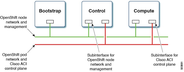
The first interface is used for the node network and the second one is used for the pod network. The second interface also carries Cisco ACI control plane traffic. A VLAN tagged subinterface is configured on the second interface to carry the cluster's pod traffic and also the Cisco ACI control plane traffic.
Installation Process
The following sections detail the steps required to install the OpenShift cluster using the ACI CNI.
Configuring the OpenShift Installer
Use this procedure to configure the OpenShift installer.
Before you begin
Download the OpenShift installer and OC client.
For details of the location from where you can download the installer , see the OpenShift 4.13 document titled, Installing a Cluster on Bare Metal with Network Customizations.
Procedure
|
Create the |
Configuring ACI Infra and CNI
Use this procedure for configuring ACI infra and CNI using acc-provision.
Procedure
|
Sample ACI configuration:
Customize the sample Run the This generates a new |
Preparing Custom Network Configuration for OpenShift Nodes
ACI CNI requires additional VLANs to be extended towards each OpenShift node. Additional VLANS are required for master and worker nodes, but not required for the bootstrap node.
You can configure additional VLANs on the interface that will be configured with the node network subnet, or can be configured on an additional physical interface on the hosts.
The two options available for configuring additional VLANs are listed below, you can use either of these:
-
A Cisco script that modifies ignition files before the installation. This method is preferred for environments with uniform hardware, where the interface names on all master nodes should be the same, and likewise, all interfaces on worker nodes should be the same. However, it is important to note that the interfaces on master nodes and worker nodes can differ. See the Ignition Files Modification section. In this method you must ensure DHCP server for node network.
-
Network configuration using kernel arguments in the PXE boot configuration. This option enables you to create individual network configuration(s) per node server. See the Additional Network Configuration Using PXE section.
Ignition Files Modification
Use this procedure for configuring ignition files for the bare metal nodes.
Before you begin
Prepare the Ignition Files
From Github download the config.yaml and update_ign.py files. This script updates the CoreOS ignition file, with additional NIC configuration, required to extend the Cisco ACI
internal network (Infra VLAN) up to the server level. This interface is used to carry VxLAN traffic from OVS towards the ACI
leaf switch with an appropriate tag for the pod network. The script offers four options for node and pod network configuration:
-
Single interface for node network and bond interface for infra network.
-
Bond interface for both node and infra networks.
-
Bond interface for node network and single interface for infra network.
-
Single interface for both node and infra networks.
Each of the above options have been illustrated as shown below:
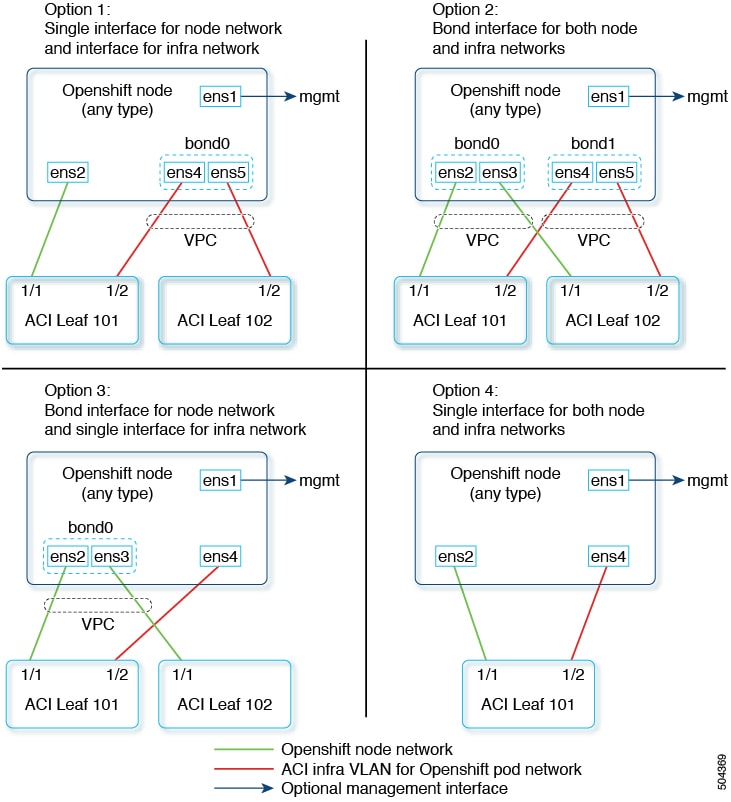
Note |
Node network is configured as VLAN subinterface of either bond0 or physical NIC. You can configure the server with additional VLAN(s) for management purpose or use the node network for management network. The design might be dependent on the server provisioning method (PXE or manual ISO boot). |
Read the instructions provided at the top of the update_ign.py script and accordingly update the config.yaml file to match your environment.
config.yaml file to match your environment. In the config file, specify the pair of physical interfaces used as a bond or single interface
for standalone. The script generates three ignition files: boostrap.ign, master.ign and worker.ign. Hostname should be configured from DHCP during the boot. The script does not add any static IP addresses. The node network
is assumed to use DHC and the sub-interfaces for ACI infra VLAN is configured to get IP address from the DHCP server running
on the APICs.
all:
  infra_vlan: 4093
  kubeapi_vlan: 3
  service_vlan: 202
  network_interfaces:
   node:
     mtu: 1500
   opflex:
     mtu: 1700
  os_compute_nodes:
   node_network_interface:
     - ens2
     - ens3
   aci_infra_network_interface:
     - ens4
     - ens5
  os_cp_nodes:
   node_network_interface:
     - ens1f0
     - ens1f1
   aci_infra_network_interface:
     - ens1f2
     - ens1f3
Procedure
|
Step 1 |
Create a root folder for your cluster. |
|
Step 2 |
Copy the |
|
Step 3 |
Create the manifests. |
|
Step 4 |
Extract all the ACI manifest files in |
|
Step 5 |
Create the ignition configurations. |
|
Step 6 |
Update the ignition files with the ACI CNI specific configuration(s). The ignition files are now ready and can be copied to your HTTP server, so they can be served to your nodes. The |
What to do next
Additional Network Configuration Using PXE
Use this procedure as an alternate procedure to prepare custom network configuration for OpenShift nodes.
Follow the instructions in the Installing RHCOS by using PXE or iPXE booting for Openshift 4.13 Baremetal User-Provisioned cluster on bare metal document which is available under the official OpenShift documentation.
Add the following modification(s) to the PXE menu configuration files:
DEFAULT pxeboot
TIMEOUT 20
PROMPT 0
LABEL pxeboot
    KERNEL http://<HTTP_server>/rhcos-<version>-live-kernel-<architecture>
    APPEND initrd=http://<HTTP_server>/rhcos-<version>-live-initramfs.<architecture>.img
        coreos.live.rootfs_url=http://<HTTP_server>/rhcos-<version>-live-rootfs.<architecture>.img
        coreos.inst.install_dev=/dev/sda coreos.inst.ignition_url=http://<HTTP_server>/bootstrap.ign
    ip=bond1:off:9000 ip=bond1.4093:dhcp:9000 bond=bond1:ens1f0,ens1f1:mode=802.3ad,miimon=100,lacp_rate=slow

    vlan=bond1.4093:bond0 rd.route=224.0.0.0/4::bond1.4093
In the above example, hosts are configured with an additional bond interface with two member physical interfaces, bond0 and bond1. bond1 uses VLAN tagging for ACI “Infra VLAN”. You also need a multicast route, which should be attached to the new bond subinterface.
Note |
You can also configure the primary interface (for node network), using kernel parameters. PXE Boot works in the native VLAN (no tagging), and does not support LACP bonding. If you need to use VPC / Port Channel configuration for node network interfaces, you need to configure ACI VPC Policy Group without Suspend Individual on LACP policy. |
Procedure
|
Step 1 |
Create a root folder for your cluster using the mkdir command. |
|
Step 2 |
Copy the install-config.yaml, config.yaml, and the update_ign.py in the newly created upi folder. |
|
Step 3 |
Create the manifests using the openshift-install create manifests command. |
|
Step 4 |
Extract all the ACI manifest files in |
|
Step 5 |
Create the ignition configurations. |
|
Step 6 |
Prepare PXE configuration(s) for all the server(s) and start the bare metal servers. |
What to do next
Proceed with the installation of the cluster; see the Redhat OpenShift 4.13 document.
Updating the Default Ingress Controller
For updating the default Ingress Controller publish strategy to use the ACI Loadbalancer, log in as a user with cluster-admin privileges and run the following:
oc replace --force --wait --filename - <<EOF
apiVersion: operator.openshift.io/v1
kind: IngressController
metadata:
  namespace: openshift-ingress-operator
  name: default
spec:
  endpointPublishingStrategy:
    type: LoadBalancerService
    loadBalancer:
      scope: External
EOF
For more details, see the Configuring the Default Ingress Controller for your Cluster to be Internal section in the Ingress Operator in OpenShift Container Platform Red Hat guide.
 Feedback