New and changed information
This table provides an overview of the significant changes up to this current release. The table does not provide an exhaustive list of all changes or of the new features up to this release.
|
Cisco APIC Release Version |
Feature |
|---|---|
|
6.1(4) |
Support for deploying virtual APIC using Nutanix AHV. |
Overview of Cisco virtual APIC deployment using Nutanix AHV
Beginning with Cisco APIC release 6.0(2), you can deploy a cluster wherein all the APICs in the cluster are virtual APICs. From Cisco APIC release 6.0(2), you can deploy a virtual APIC on AWS using the CloudFormation template or a virtual APIC on the ESX host using the OVF template in VMware vCenter. From Cisco APIC release 6.1(4), you can deploy a virtual APIC on an AHV host using the OVA template in Nutanix AHV (Acropolis Hypervisor). The virtual APIC can be deployed on an existing server on the customer premises.
This document provides details about deploying a virtual APIC on Nutanix AHV. For information about deploying virtual APIC using AWS, see the Deploying Cisco Virtual APIC Using AWS document and for information about deploying virtual APIC using VMware vCenter, see the Deploying Cisco Virtual APIC Using VMware vCenter document.
Modes of deployment
Two modes of deployment are supported:
-
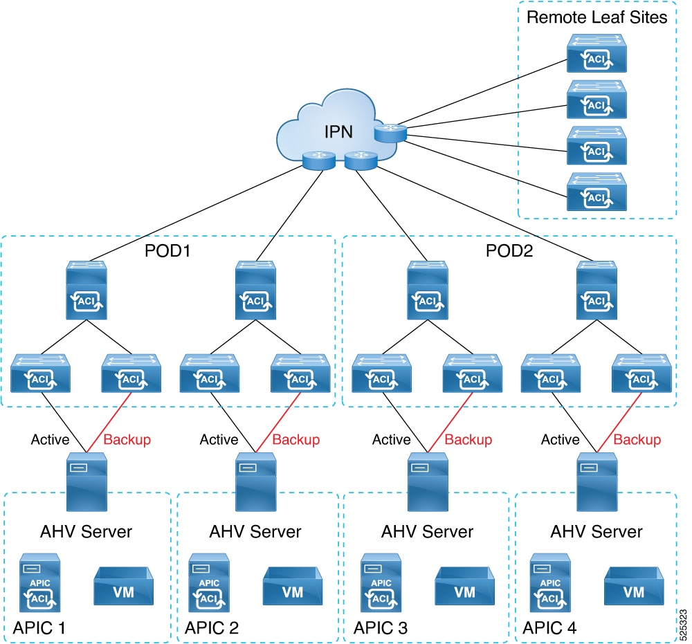
Layer 2—the AHV host, on which the virtual APIC(s) are deployed, is directly connected to the leaf switches of the ACI fabric. The AHV hosts hosting the APICs can be connected to the ACI leaf switches with active-backup uplinks.
-
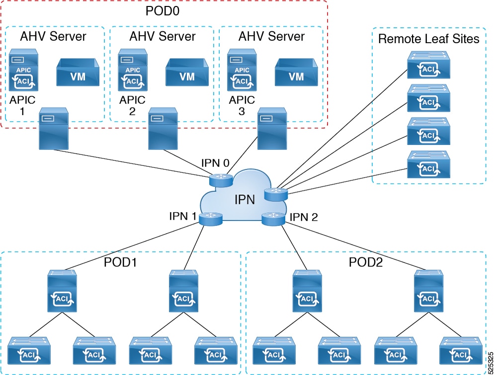
Layer 3—the AHV host, on which the virtual APIC(s) are deployed, is remotely attached to the ACI fabric, through an external network.
AHV host directly connected to the ACI fabric
In this mode, referred to as Layer 2 connected, wherein the AHV host is directly connected to the leaf switches of the ACI fabric. The AHV host(s) hosting APICs in Layer 2 mode must only use active-backup mode for uplinks.
Virtual APICs with active-backup AHV uplinks
As shown in this image, the APIC VMs are hosted on AHV hosts which are directly connected to the leaf switch(es) of the ACI fabric. One of the AHV host uplinks connected to the leaf switch is in active mode, the other is in backup mode.
AHV host remotely attached to the ACI fabric
As shown in this image, the APIC VMs are hosted on the AHV hosts which are connected to an external network and remotely attached to the ACI fabric through IPN.
Guidelines and limitations for deploying virtual APIC on AHV
These guidelines and limitations apply for deploying virtual APIC on AHV.
-
Virtual APIC deployment on Nutanix is supported only through Nutanix Prism Central. Deployment through Nutanix Prism Element is not supported because Prism Element does not provide support for OVA deployment.
-
UEFI BIOS boot configuration is not supported for virtual APIC.
-
In releases prior to Cisco ACI 6.2(1), you cannot create clusters that mix physical and virtual APIC controllers. All nodes in an APIC cluster must use the same controller type—either all physical or all virtual. For example, if APIC1 and APIC2 are physical controllers, then APIC3 must also be a physical controller.
Starting with Cisco ACI release 6.2(1), mixed mode clustering is supported based on the controller type. You can now use clusters with all virtual, all physical, or a mix of physical and virtual APICs (except AWS virtual controllers).
-
Mixed-mode clusters with different PIDs are not supported. For example, a cluster combining the APIC-SERVER-NUTANIX-M1 PID and the APIC-SERVER-VMWARE-M1 PID is not allowed.
-
Cluster and fabric security is provided using self-signed certificates.
-
If multiple APICs are hosted on the same AHV host and fabric recovery is triggered, always begin the recovery process by starting with a cluster size of 1. After completing ID recovery, expand the cluster to 3 nodes.
Networking prerequisites
Networking prerequisites
Ensure that the network related prerequisites are met before deploying the virtual APIC on an AHV:
-
UCS hardware prerequisites:
-
Ensure that LLDP and port-channel are disabled.
-
From vNIC interfaces, ensure that VLAN mode is set to Trunk mode.
-
-
Networking prerequisites:
-
DVS refers to OVS in Nutanix and port-group refers to subnet in Nutanix.
-
VLAN configuration is not required on the subnet created on OVS.
-
If uplink is Access for management/OOB network, then VLAN 0 is configured.
-
If uplink is Trunk for management/OOB network, then the respective VLAN must be configured. For example, VLAN 100.
-
Infrastructure subnet is configured with infrastructure or inband VLANs. When infrastructure VLAN is provided, LLDP does not work as VLAN 0 is mandatory to bypass LLDP.
NIC configuration for virtual APIC VM is updated with attachement type as Trunked. VLANs such as infrastructure or inband VLANs are allowed if configured.
-
-
Active-active uplink configuration for AHV hosts is not supported. Only active-backup uplink configuration is supported.
-
Network controller Managed subnets are not supported. Only VLAN basic subnets are supported for infrastructure subnet.
-
IPAM enabled subnet is not supported for the management and infra subnets.
-
(For Layer 2 virtual APIC) See Deploy virtual APIC using Nutanix.
-
Virtual machine specifications
Ensure that the AHV hosts can support the VM specifications mentioned in these tables.
|
CPU |
16 vCPU of 2.5 GHz or higher |
|
Memory |
96 GB of RAM |
|
Storage |
|
|
Network |
Two interfaces.
Latency tolerance between virtual APICs is up to 50 ms. |
|
CPU |
8 CPU of 2.5 GHz or higher |
|
Memory |
32 GB of RAM |
|
Storage |
|
|
Network |
Two interfaces:
Latency tolerance between virtual APICs is up to 50 ms. |
|
CPU |
32 vCPU of 2.5 GHz or higher |
|
Memory |
192 GB of RAM |
|
Storage |
|
|
Network |
Two interfaces.
Latency tolerance between virtual APICs is up to 50 ms. |
Nutanix platform software versions
-
Nutanix Prism Central - pc.2024.2.0.1
-
Nutanix AOS - 6.10.1.5
Deploy virtual APIC using Nutanix
Follow these steps to deploy virtual APIC (Layer 2 and Layer 3) on an AHV host using Nutanix.
Before you begin
Procedure
|
Step 1 |
Upload the virtual APIC OVA file to Nutanix Prism Central. |
||
|
Step 2 |
Deploy the virtual APIC. |
||
|
Step 3 |
In the Configuration screen of the wizard, specify these configurations. |
||
|
Step 4 |
In the Resources screen of the wizard, specify the resource configurations. |
||
|
Step 5 |
In the Management screen of the wizard, ensure that UTC timezone is selected in the Timezone drop-down list and click Next.
|
||
|
Step 6 |
In the Review screen of the wizard, review the information and click Create VM. |
||
|
Step 7 |
Turn on the VM and specify admin password and OOB IP address. |
||
|
Step 8 |
Repeat this procedure for each virtual APIC based on the cluster size. For example, if you are building a 3-node cluster, you need to repeat this procedure for each virtual APIC deployment. Ensure that all the VMs are powered on and same admin password is provided as the first virtual APIC before proceeding to bootstrapping and cluster bringup procedure. See the detailed Bringing up the Cisco APIC Cluster Using the GUI procedure in the Cisco APIC Getting Started Guide. Use the IP address of APIC 1 to access the APIC Cluster Bringup GUI. |
||
|
Step 9 |
(Only for Layer 2 virtual APIC) Perform LLDP passthrough to discover the other virtual APICs in the cluster. See Perform LLDP passthrough using Nutanix. |
Perform LLDP passthrough using Nutanix
(Only for Layer 2 virtual APIC) Follow these steps to perfom LLDP passthrough using Nutanix. LLDP passthrough ensures that LLDP packets can pass from the Layer 2 virtual APIC to the leaf switch.
Perform these steps either from any CVM or Nutanix Prism Element. Repeat this procedure for each virtual APIC based on the cluster size.
Procedure
|
Step 1 |
Use the Example: |
||
|
Step 2 |
Use the Example: |
||
|
Step 3 |
Use the Example: |
||
|
Step 4 |
Use the Example: |
||
|
Step 5 |
Use the Example: |
||
|
Step 6 |
Configure these commands using the collected information such as bridge name, host IP or name, VM name, MAC address, uplinks, and tap information to perform LLDP passthrough. Example:
|
Create an ACI network with a layer 3 connected APIC cluster
The procedures in this section establish the connectivity between the created virtual APIC cluster, and the remote ACI fabric. The layer 3 connected APIC cluster is able to discover the fabric nodes using DHCP relay and an OSPF or BGP underlay provided by the IPN.
This list outlines the steps to deploy an ACI network with a layer 3 connected virtual APIC cluster:
Procedure
|
Step 1 |
Configure the IPN as described is these procedures — Provision the fabric-facing IPN device and Provision the APIC cluster-facing IPN device. |
|
Step 2 |
Bring up the APIC cluster using the Bringing up the APIC Cluster procedure desribed in the Cisco APIC Getting Started Guide. |
|
Step 3 |
Configure a layer 3 connection for the APIC cluster to communicate over the IPN with the fabric pod. See Prepare connectivity to the fabric pod. |
|
Step 4 |
Bring up the fabric pod. The fabric will be discovered by the APIC cluster over the layer 3 connection as described in Summary of fabric discovery and registration. |
What to do next
You can connect additional fabric pods and remote leaf sites to the layer 3 connected APIC cluster in a similar manner.
Guidelines and restrictions to deploy APIC cluster connectivity to the fabric over a layer 3 network
When deploying a virtual layer 3-connected APIC cluster, follow these guidelines and limitations.
-
Ensure that the APIC connected subnet is configured for the APIC Infrastructure Layer 3 Network VLAN. If in-band management is used, the subnet must be configured as a trunk allowing both the Infrastructure Layer 3 Network VLAN and the in-band management VLAN.
-
All APIC cluster sizes are supported in a layer 3 connected APIC pod.
-
APICs in a layer 3 connected APIC pod cannot form a cluster with APICs within the fabric pod. In this topology, there should be no APICs in the fabric pod.
-
The layer 3 connected APICs can be in the same subnet or in different subnets. In case of same subnet, configure "no ip redirects" in APIC-connected IPN interface.
-
The layer 3 connected APICs can be geographically distributed from each other provided that the latency between APICs and with the fabric pod does not exceed 50 milliseconds round-trip time (RTT), which translates approximately to a geographical distance of up to 2,500 miles.
-
Although any device that can meet the IPN network requirements can be used as an IPN device, we recommend to deploy, when possible, switches of the Cisco Nexus 9300 Cloud Scale family. These are the devices most commonly found in production and also the devices more frequently validated in Cisco internal testing. For further information about IPN device requirements, see "Inter-Pod Connectivity Deployment Considerations" in the ACI Multi-Pod White Paper.
-
The APIC subnets must be advertised to the spines as either OSPF or BGP routes. Both OSPF and BGP are supported as underlay protocols between the APIC nodes and the IPN devices
-
As all control plane traffic between the APIC cluster and the fabric pod traverses the IPN, we recommend configuring QoS for this traffic. See the Configuring QoS section in this guide.
-
APIC Cluster Connectivity to the Fabric Over a Layer 3 Network does not support the following:
-
ACI CNI for Kubernetes (Redhat Openshift, SUSE/Rancher RKE, Upstream Kubernetes on Ubuntu)
-
ACI ML2 for Openstack (Redhat Openstack, Canonical Openstack)
-
-
APIC cluster connectivity to the fabric over a Layer 3 network supports strict mode. In strict mode, you must approve the controller explicitly.
Provision the APIC cluster-facing IPN device
This section describes the configuration of the IPN device connected to Pod 0, the APIC cluster pod. With reference to the topology for Layer 3 in the AHV host remotely attached to the ACI fabric section, the cluster-facing IPN device is shown as IPN0. As a recommended practice, the IPN0 comprises two devices for redundancy. The fabric interface of each APIC is dual-homed to the two devices. In this configuration example, two Cisco Nexus 9000 series switches (IPN0a and IPN0b) are configured with these choices:
-
VLAN 1500 is used as interface VLAN for the APICs.
-
The switch interfaces are configured as layer 2 trunk ports. As an alternative, the interfaces could be access ports if the APIC fabric interface is configured to use VLAN 0 during APIC setup.
-
Both switches are configured using HSRP to share a single IP address that serves as the APIC subnet default gateway address.
-
APIC subnets are advertised to the spines using OSPF as the underlay protocol. As an alternative, a BGP underlay could be deployed.
# Example configuration of IPN0a:

interface Vlan1500
  no shutdown
  vrf member IPN
  no ip redirects
  ip address 172.16.0.252/24
  ip ospf passive-interface
  ip router ospf 1 area 0.0.0.0
  hsrp version 2
  hsrp 1500
    ip 172.16.0.1

interface Ethernet1/1
  switchport mode trunk
  switchport tru allowed vlan 1500
  spanning-tree port type edge trunk


# Example configuration of IPN0b:

interface Vlan1500
  no shutdown
  vrf member IPN
  no ip redirects
  ip address 172.16.0.253/24
  ip ospf passive-interface
  ip router ospf 1 area 0.0.0.0
  hsrp version 2
  hsrp 1500
    ip 172.16.0.1

interface Ethernet1/1
  switchport mode trunk
  switchport tru allowed vlan 1500
  spanning-tree port type edge trunk
Provision the fabric-facing IPN device
This section describes the configuration of the MPod IPN, which is the IPN device connected to a fabric pod. The IPN is not managed by the APIC. It must be preconfigured with this information:
-
Configure the interfaces connected to the spines of the fabric pod. Use Layer 3 sub-interfaces tagging traffic with VLAN-4 and increase the MTU at least 50 bytes above the maximum MTU required for inter-site control plane and data plane traffic.
-
Enable OSPF (or BGP) on the sub-interface specifying the OSPF process and area ID.
-
Enable DHCP Relay on the IPN interfaces connected to spines.
-
Enable PIM.
-
Add bridge domain GIPo range as PIM Bidirectional (bidir) group range (default is 225.0.0.0/15).
A group in bidir mode has only shared tree forwarding capabilities.
-
Add 239.255.255.240/28 as PIM bidir group range.
-
Enable PIM on the interfaces connected to all spines.
 Note |
Multicast is not required for a single pod fabric with a layer 3-connected APIC cluster, but it is required between pods in a multi-pod fabric. |
Note |
When deploying PIM bidir, at any given time it is only possible to have a single active RP (Rendezvous Point) for a given multicast group range. RP redundancy is hence achieved by leveraging a Phantom RP configuration. Because multicast source information is no longer available in Bidir, the Anycast or MSDP mechanism used to provide redundancy in sparse-mode is not an option for bidir. |
This switch configuration example is for a switch deployed as the MPod IPN. The DHCP relay configuration allows the fabric to be discovered by the APIC cluster. The deployment of a dedicated VRF in the IPN for inter-pod connectivity is optional, but is a best practice recommendation. As an alternative, you can use a global routing domain.
Example: OSPF as the underlay protocol
feature dhcp
feature pim
service dhcp
ip dhcp relay

# Create a new VRF.
vrf context overlay-1
  ip pim rp-address 12.1.1.1 group-list 225.0.0.0/15 bidir
  ip pim rp-address 12.1.1.1 group-list 239.255.255.240/28 bidir

interface Ethernet1/54.4    #spine connected interface
  mtu 9150
  encapsulation dot1q 4
  vrf member overlay-1
  ip address 192.168.0.1/30
  ip ospf network point-to-point
  ip router ospf infra area 0.0.0.0
  ip dhcp relay address 172.16.0.2  #infra address of APIC 1
  ip dhcp relay address 172.16.0.3  #infra address of APIC 2
  ip dhcp relay address 172.16.0.4  #infra address of APIC 3
  no shutdown

interface loopback29
  vrf member overlay-1
  ip address 12.1.1.2/30

router ospf infra
  vrf overlay-1
    router-id 29.29.29.29
Example: BGP as the underlay protocol
router bgp 65010
  vrf IPN
    neighbor 192.168.0.2 remote-as 65001
      address-family ipv4 unicast
        disable-peer-as-check
In the BGP configuration, the disable-peer-as-check command is needed for multi-pod because each pod uses the same ASN.
Prepare connectivity to the fabric pod
Before bringing up the fabric pod (Pod 1), you first must pre-configure the layer 3-connected APIC cluster (Pod 0) for connectivity through the IPN to a spine in the fabric pod. This is necessary for automatic fabric discovery.
Before you begin
-
If the layer 3 conncted virtual APIC cluster is deployed in a separate security zone from the fabric, configure the firewall to allow any necessary protocols and ports.
-
Configure the inter-pod network (IPN) device that is connected to the fabric pod spines.
-
Configure a fabric external routing profile.
-
Configure an OSPF interface policy if you are using OSPF as the underlay protocol.
Procedure
|
Step 1 |
Log in to one of the APICs in the layer 3 connected cluster. |
|
Step 2 |
Choose . |
|
Step 3 |
In the work pane, click the + symbol in the Pod Fabric Setup Policy page. The Set Up Pod TEP Pool dialog box opens. |
|
Step 4 |
In the Set Up Pod TEP Pool dialog box, complete the following steps:
|
|
Step 5 |
In the navigation pane, expand Quick Start and click Add Pod. |
|
Step 6 |
In the work pane, click Add Pod. |
|
Step 7 |
In the Configure Interpod Connectivity STEP 1 > Overview panel, review the tasks that are required to configure interpod network (IPN) connectivity, and then click Get Started. |
|
Step 8 |
In the Configure Interpod Connectivity STEP 2 > IP Connectivity dialog box, complete the following steps: |
|
Step 9 |
In the Configure Interpod Connectivity STEP 3 > Routing Protocols dialog box, in the OSPF area, complete the following steps to configure OSPF for the spine to IPN interface: |
|
Step 10 |
In the Configure Interpod Connectivity STEP 3 > Routing Protocols dialog box, in the BGP area, leave the Use Defaults checked or uncheck it. The Use Defaults check box is checked by default. When the check box is checked, the GUI conceals the fields for configuring Border Gateway Protocol (BGP). When it is unchecked, it displays all the fields. If you uncheck the box, configure the following steps: |
|
Step 11 |
Click Next. |
|
Step 12 |
In the Configure Interpod Connectivity STEP 4 > External TEP dialog box, complete the following steps: |
|
Step 13 |
Click Next. The Summary panel appears, displaying a list of policies created by this wizard. You can change the names of these policies here.
|
|
Step 14 |
Click Finish. |
What to do next
Monitor the discovery and registration of the fabric nodes by APIC, as summarized in the following section.
Summary of fabric discovery and registration
This is a summary of the switch registration and discovery process.
-
The IPN, acting as a DHCP relay agent, forwards DHCP requests from the spine to the APIC.
-
Spine switch is now visible to the APIC and appears the under Nodes Pending Registration in the Fabric Membership screen. Navigate to Fabric > Inventory > Fabric Membership.
-
Register the spine switch on the APIC .
-
The APIC allocates an IP address for the spine interface to the IPN and a TEP IP from the TEP pool configured for the fabric pod containing the spine. At this point, the spine joins the ACI fabric.
-
The spine advertises the TEP subnet to the IPN through OSPF or BGP so that the IPN learns this subnet.
-
The spine acts as a DHCP relay agent for its connected leaf switches, and forwards the requests to the APIC.
-
The leaf switches are then visible to the APIC and appear in the section of Nodes Pending Registration in Fabric > Inventory > Fabric Membership.
-
You must manually register these leaf switches on the APIC.
-
After a leaf switch is registered, the APIC forwards the TEP IP address and DHCP configuration information to the leaf, which then joins the ACI fabric. Through this discovery process, the layer 3-connected APIC cluster discovers all switches in the fabric pod.
Configure QoS for the layer 3 connected APIC cluster
As all traffic between the APIC cluster and the fabric traverses the IPN, we recommend configuring QoS for this traffic. Specific recommendations are as follows:
Note |
The configuration examples in this section are for a Cisco Nexus 9000 series switch which can be used as an IPN device. The configuration may differ when using a different platform. |
-
Enable a DSCP class CoS translation policy.
-
Retain end-to-end DCSP values for all IPN traffic. When the DSCP class CoS translation policy is enabled, the spine switches will set the DSCP value in packets sent to the IPN per this policy. Traffic destined to the APICs will use the Policy Plane class. Inter-pod control plane traffic (that is, OSPF and MP-BGP packets) will use the Control Plane class. Ensure that the Policy Plane class is configured for Expedited Forwarding (EF) and the Control Plane class is configured for CS4. The IPN network can be configured to prioritize these two classes to ensure that the policy plane and control plane remain stable during times of congestion.
This example shows the configuration for setting QoS for policy plane traffic on a Cisco Nexus 9000 series switch used as an IPN device.
interface Vlan1500 no shutdown vrf member overlay-1 ip address 172.16.0.2/24 ip ospf passive-interface ip router ospf 1 area 0.0.0.0 hsrp version 2 hsrp 100 ip 172.16.0.1 ip access-list APIC_Cluster 10 permit ip 172.16.0.0/24 any class-map type qos match-all APIC-Class match access-group name APIC_Cluster policy-map type qos APIC_Policy class APIC-Class set dscp 46 interface Ethernet1/1 switchport mode trunk switchport access vlan 1500 service-policy type qos input APIC_Policy interface Ethernet1/2 switchport mode trunk switchport access vlan 1500 service-policy type qos input APIC_Policy interface Ethernet1/3 switchport mode trunk switchport access vlan 1500 service-policy type qos input APIC_Policy -
We also recommend that you rate limit non-policy-plane traffic to the APIC to prevent drops on policy plane traffic. Deploy a policer on the cluster-facing IPN to limit traffic with a DSCP value other than 46 (EF) to 4 Gbps with burst of 60 Mbps. This example shows a rate limiting configuration on a Cisco Nexus 9000 series switch used as an IPN device.
class-map type qos match-all no_rate_limit match dscp 46 policy-map type qos APIC_Rate_Limit class no_rate_limit class class-default police cir 4 gbps bc 7500 kbytes conform transmit violate drop interface Ethernet1/1-3 switchport mode trunk switchport access vlan 1500 service-policy type qos input APIC_Policy service-policy type qos output APIC_Rate_Limit
Configure in-band management
When you deploy in-band management with a layer 3 connected APIC cluster, the in-band management VRF (mgmt:inb) is not routed through the spines to the IPN. Connectivity to the in-band management interfaces on the APIC must be routed from an L3Out configured from one of the border leaf switches. This L3Out should be configured in the mgmt tenant for the in-band management VRF.
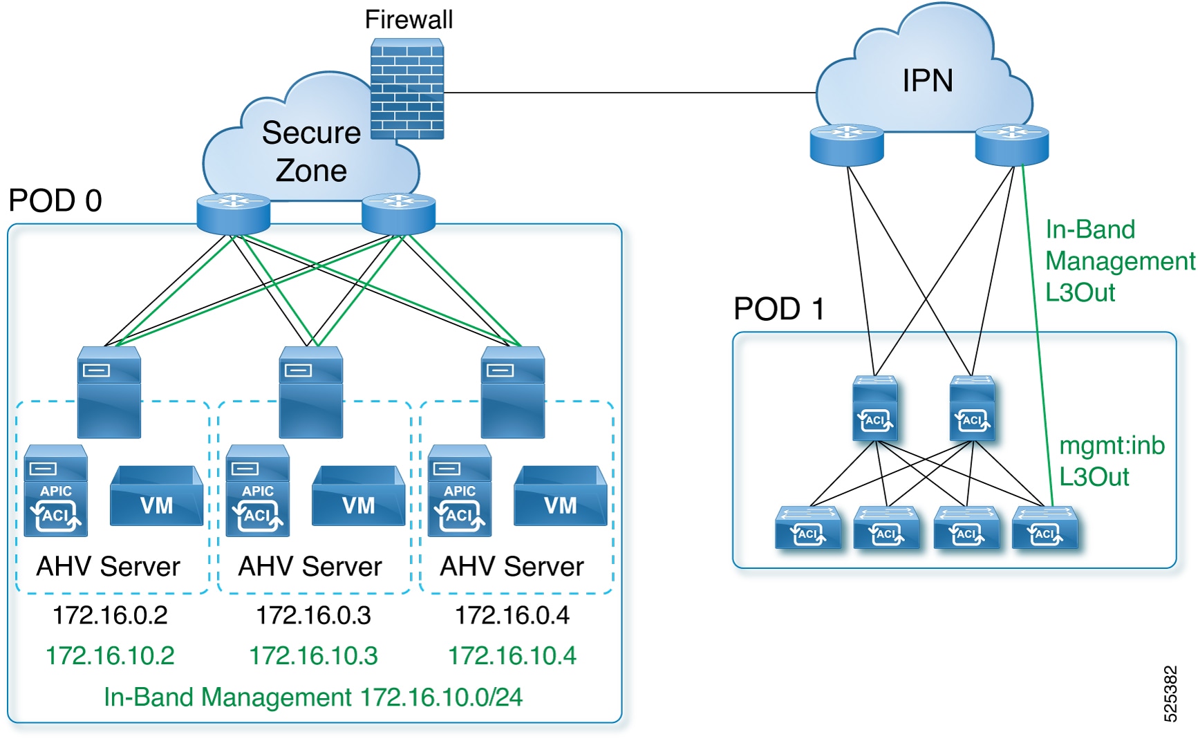
Use this procedure to configure in-band management for the layer 3 connected APIC cluster.
Before you begin
Configure the in-band VLAN in the APIC-connected subnet in OVS.
Procedure
|
Step 1 |
Configure the APIC upstream switches. Example: You can route the in-band management network using the IPN VRF or you can choose a different VRF. |
||
|
Step 2 |
Configure the APICs for in-band management using the normal in-band management configuration procedure.
For additional information about configuring in-band management, see the "Static In-band Management" chapter of the Cisco APIC and Static Management Access tech note. |
||
|
Step 3 |
Configure the APIC interfaces on the upstream switches. The APIC-connected interface must be a trunk interface. If the APICs were initialized with an infrastructure VLAN other than 0, you can configure the interface as in the following example.
|
 Feedback