Overview of Cisco Modeling Labs
Cisco Modeling Labs
Cisco Modeling Labs 1.0 is a scalable and extensible software platform that enables operators, engineers, network designers, and architects to design Cisco-based networks and run simulations using virtual versions of selected Cisco operating systems. Cisco Modeling Labs comprises the Cisco Modeling Labs server and the Cisco Modeling Labs client. Together, they provide a sandbox environment that facilitates the design, configuration, visualization, and simulation of network topologies quickly and efficiently.
- Cisco Modeling Labs server—A shared resource containing the capability to initiate topologies using installed virtual images.
- Cisco Modeling Labs client—A point-and-click GUI that simplifies topology creation and initial device configurations along with continuous updates, and permits access to the Cisco Modeling Labs server functionality.
- Virtual Images—Cisco Modeling Labs 1.0 includes a Cisco IOSv virtual image. Additional Cisco virtual images are available for use. However, they must be installed separately. See the Release Notes for Cisco Modeling Labs 1.0 for the most up-to-date list of supported virtual images. An Ubuntu 14.04 server has been tested with Cisco Modeling Labs. The Ubuntu server must be downloaded separately. To access the server, go to: http://cloud-images.ubuntu.com/trusty/current. From this page, download the clouding-amd64 RAW (img) image trusty-server-cloudimg-amd64-disk1.img. Together, the virtual images and Ubuntu server provide a powerful platform for creating, modifying, and testing the virtual network scenarios.
Cisco Modeling Labs Server Components
The Cisco Modeling Labs server is a Linux distribution that is bundled within the VMware Open Virtual Appliance (OVA) file for VMware ESXi. The bundle includes all the supporting files. The Cisco Modeling Labs server is a shared resource used by end users to run backend functions, such as router bootstrap configurations, spinning up routers to operate with designated operating systems, and modifying and testing configurations.
Cisco Modeling Labs 1.0 comprises a framework of components. The main components are:
- OpenStack—An open-source platform for creating and managing large groups of virtual servers in a cloud-computing configuration. It is used for node control, management, and networking.
- AutoNetkit—An automated configuration engine that uses templates to provide working router configurations based on user-supplied and default parameters for each virtual machine.
- Services Topology Director—Generates OpenStack calls for the creation of virtual machines and links based on the XML topology definition created by the Cisco Modeling Labs client. Additionally, it provides the bootstrap configuration, which can be auto-generated, generated manually, or imported.
Cisco Modeling Labs Client
For further information on the Cisco Modeling Labs client, see Using the Cisco Modeling Labs Client Overview.
Virtual Images
Cisco Modeling Labs 1.0 includes the Cisco IOSv 15.4(2)T virtual image. The operation and syntax used with the virtual images are the same as a physical platform running the same software.
See the Release Notes for the Cisco Modeling Labs 1.0 for more information on Cisco IOSv virtual software supported features.
Cisco Modeling Labs Component Requirements
The following tables identify the minimum requirements for installing and operating the Cisco Modeling Labs 1.0 Corporate Edition. For additional information, see the Cisco Modeling Labs 1.0 Corporate Edition Client Installation Guide and the Cisco Modeling Labs 1.0 Corporate Edition System Administrator Installation Guide. These guides provide detailed information on platform requirements for installing and operating Cisco Modeling Labs 1.0 Corporate Edition for system administrators and end users.
| Requirement | Description |
|---|---|
| Small to Medium | Server with a capacity to run 30-40 nodes |
| Memory (RAM) | 128 GB |
| Disk Space | 1 TB minimum |
| Processors | 16 CPU cores |
| Large | Server with a capacity to run 40-100 nodes |
| Memory (RAM) | 256 GB |
| Disk Space | 1 TB minimum |
| Processors | 40 CPU cores |
| Requirement | Description |
|---|---|
| Operating System | Either of the following: |
| Memory (RAM) | 500 MB |
| Disk Space | 150 MB |
| Requirement | Description | ||
|---|---|---|---|
| Java Runtime Environment (JRE) | For Windows and Mac OS X, either of the following: | ||
| Browser | One of the following:
|
Cisco Modeling Labs Framework
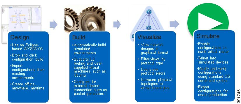
Cisco Modeling Labs 1.0 includes numerous features that enable you to create and simulate small and large network designs. This user guide is organized in a task-based format where the main features are grouped into four sections referred to as phases.
The following items describe each phase which should help you determine which section to refer to when using this guide:
- Design—This phase includes the tasks for creating a network topology. You use a blank canvas to create topologies from scratch or import existing network topologies. You can also view your topologies on a geographic map and adjust where and how interfaces are used on each device.
- Build—This phase includes the tasks associated with configuring routers, external connections, and servers, creating the required configurations, setting up interfaces, IP addressing, and routing protocols for the virtual routers. There are several ways to create these configurations. You can use the AutoNetKit functionality to set up the initial configuration or you can input your own configuration details. Whatever configurations you create in this phase will be the configurations that the Cisco Modeling Labs server will use when it initiates the node simulations.
- Visualization—This phase is optional and operates only if you use AutoNetKit to create your configurations during the Build phase. It includes the tasks related to running visualization scenarios of your network design and configuration. It provides visual views of your topology whereby you can see how the nodes will interact with each other in specific circumstances including physical set up as well as with specific routing protocols such as ISIS and OSPF. It also supports MPLS and BGP.
- Simulation—This phase includes the tasks for initiating the nodes and making them active. Once the nodes are operational, you can connect to the consoles using Telnet or SSH, as you would connect to a router console. You can run connectivity tests and modify configurations. This is where the power of the product is realized since you can modify and test configurations as if you were on actual physical devices. In this phase, you can also save your configurations and extract them for sharing with others or saving them and using them as reference when configuring the production network.
 Feedback