Simulate the Topology

Simulate the Topology Overview

The simulation phase is when you run the simulation of your topology design. The Simulation perspective provides a set of views that support the simulation phase. By comparison, the design and build activities occur in the Design perspective, which provides a set of views that support the design activity. Some views in the Simulation perspective can also be viewed in the Design perspective.

Simulation Perspectives and Views
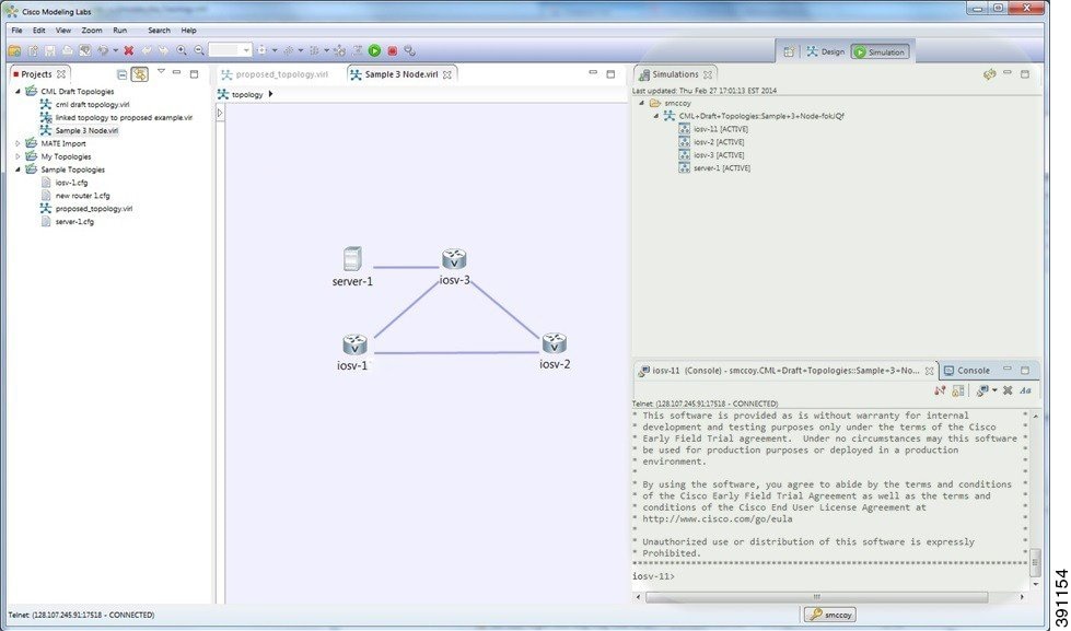
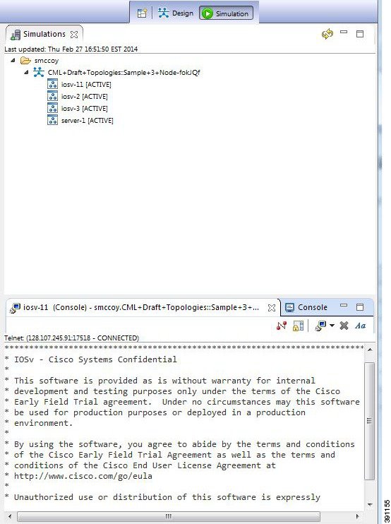
The main areas of focus within the Simulation perspective are the Simulations view and the Console view. The following figure highlights the Simulation and Console views for a running simulation.
Figure 1. Simulation Perspective Initial Display


From the View menu, you can open additional views in the perspective and arrange the open views by dragging them within the perspective workspace. See the online help and the section Customizing Perspectives for more information.

Note


To reset your current perspective to its original configuration when the workbench was first opened, right-click the perspective button and select Reset.

Node Limits

In Cisco Modeling Labs 1.0 Corporate Edition, the number of nodes you can run is limited by the resources available on the server and the number of licenses available. In Cisco Modeling Labs 1.0 Corporate Edition, the design limit is 1,000 nodes.

During the simulation phase, you can perform the tasks described in the following sections.

Launch a Simulation

Before You Begin
  • Complete the topology design.
  • Complete the task of building the nodes and interfaces.
  • (Optional) Generate the configuration using AutoNetkit.

    Caution


    When you manually make changes to a node configuration and bypass AutoNetkit auto-generation, those changes do not appear in the topology view of the Design perspective or Simulation perspective. For example, if you use the hostname command to change the host name from iosv-1 to Router-1 in the configuration, the node name in the topology view and in other related views remains as iosv-1.
  • Open the desired topology.

    Note


    The topology should be open and visible in the Topology Editor. If you have multiple topologies open in the Topology Editor, simulation will launch for the currently active view.
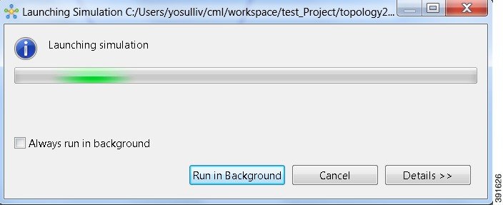
    Step 1   From the toolbar, click the Launch Simulation button. The simulation launches and provides a unique identifier, which means that multiple instances of the topology can be launched and each will have a unique name.
    Step 2   In the Launching Simulation dialog box, select any of the following actions:

    1. Check the Always run in the background check box. All future node start requests, stop requests, and simulation launch requests run in the background and do not display dialog boxes.
      Note    To control the background setting, choose File > Preferences > General.
    2. Click Run in background. The dialog box closes when the node simulation starts.
    3. Click Cancel to return to the Design view.
    4. Take no action, and the node simulation launches momentarily.
      Tip    When you click Run in background, the status bar displays a progress icon. Click the icon to display a compact view of the activity progress. If the background activity encounters an error, the icon shows a red X. Click the error icon to display the error dialog.
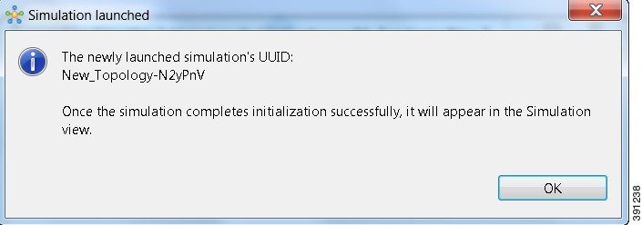
    Step 3   In the Simulation launched dialog box, click OK.

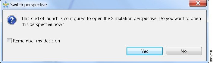
    Step 4   When prompted to switch to the Simulation perspective, click Yes.

    Note    We recommend that you switch to the Simulation perspective to view the running simulation and to connect to node consoles.

    The Cisco Modeling Labs client tracks the state of the simulations. All launched simulations appear in the Simulations view. Status messages are displayed in the Console view. After the Cisco Modeling Labs server has started the simulation launch, a confirmation dialog box appears with an identifier assigned to the simulation by the Cisco Modeling Labs server.
    When the nodes are running on the Cisco Modeling Labs server, they are displayed in the Simulations view with the status as [ACTIVE], as shown in the following figure.
    Figure 2. Simulation Launched in Simulation View


    Connect to a Simulation Node Console

    Before You Begin
    • Launch a simulation.
    • Ensure that the Simulation perspective is active.
    • Ensure that the Simulations view and Console view are displayed.

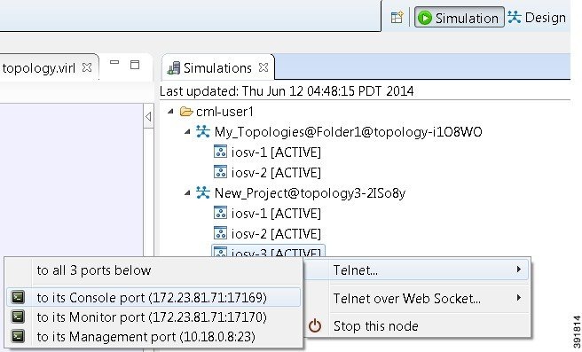
      Step 1   To connect to a console for a specific node, right-click the node in the Simulations view and choose Telnet > to its Console port.

      Figure 3. Connecting to a Node Console


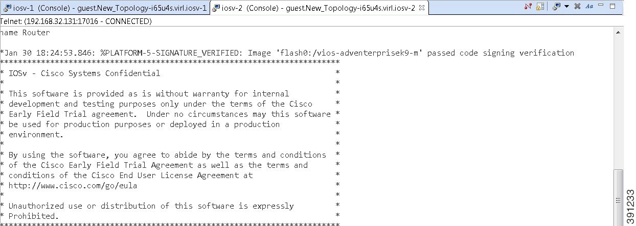
      A new Terminal view opens.

      Figure 4. Terminal View


      Step 2   To disconnect a terminal from the simulation, click Disconnect in the Terminal view toolbar or click the Close icon in the Terminal view.
      Note    When you disconnect or close a terminal view, all text in the view is discarded.
      Tip    After you disconnect a terminal, but do not close the terminal window, you can press Enter to reconnect the terminal.

      Stop an Entire Simulation

      There are several methods for stopping an entire simulation. These are discussed in the following sections.

      Method 1: Stop an Entire Simulation from the Toolbar


        Step 1   In the toolbar, click the Stop Simulations button. A Stop Simulation(s) dialog box appears.
        Step 2   In the Simulation column, click once to highlight the simulation to stop.
        Step 3   (Optional) To save the configurations, click the adjacent setting in the Extract Configurations? column until the prompt changes to Yes.
        Note    Configurations for server nodes are not extracted.
        Step 4   (Optional) To close the internal terminals associated with the simulation, click the adjacent setting in the Close Terminals? column until the prompt changes to Yes.
        Note    External terminal connections are not stopped as part of this operation and must be closed manually.
        Step 5   To stop the simulation, click the adjacent setting in the Stop Simulation? column until the prompt changes to Yes.
        Step 6   Click OK to confirm stopping the simulation, or click Cancel to leave the simulation running.
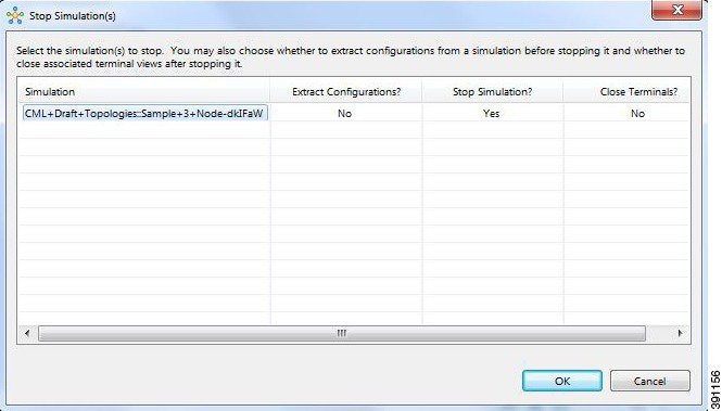
        Figure 5. Stop Simulation(s) Dialog Box


        On Mac OS X, you update the values for Extract Configurations?, Stop Simulation? and Close Terminals? in the columns directly. You do not need to select the name of the simulation.

        Note    When stopping a simulation, you cannot attempt to stop individual nodes running in the simulation at the same time. This behavior is not supported.

        Method 2: Stop an Entire Simulation from the Simulations View


          Step 1   In the Simulations view, right-click the Simulation name and select Stop Simulation. The Stop simulation confirmation dialog box appears.
          • (Optional) Check the Extract configurations before stopping simulation check box to save the current configurations.
          • (Optional) Check the Close associated terminal views check box to close all the open internal terminals associated with the specific simulation. External terminals are not closed.
          Step 2   Click OK to stop the simulation. Once selected, all nodes in the simulation start shutting down. It may take a few minutes for the simulation to shut down completely and to disappear from the Simulations view.
          Note    When stopping a simulation, you cannot attempt to stop individual nodes running in the simulation at the same time. This behavior is not supported. Note too for instances where a user account expires, any running simulations for that user continue to run. Since the user account can no longer log into stop them, they will remain active until the next system reboot or until the system administrator explicitly stops them.

          Stop a Single Node


            Step 1   In the Simulations view, right-click the node to stop and select Stop this node.
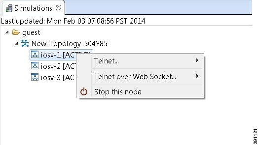


            The Are you sure dialog box appears.

            Step 2   Click OK to stop the simulation. Alternatively, click Cancel to abandon the operation and return to the simulation.
            Note    When you click OK, the node stops without saving any changes to the configuration.
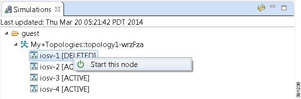
            When a node is stopped, its status changes to [DELETED].

            What to Do Next

            • (Optional) Start a node.
            • (Optional) Stop the simulation.

            Start a Single Node


              Step 1   Right-click a stopped node. When a node is stopped, its status changes to [DELETED].
              Step 2   Click Start this node.


              The Requesting start dialog box appears.
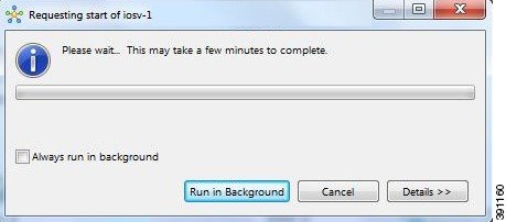


              Step 3   Choose one or more of the following actions:
              1. Check the Always run in the background check box. All future node start requests, stop requests, and simulation launch requests run in the background and do not display dialog boxes.
                Note    To control the background setting, choose File > Preferences > General.
              2. Click Run in background.

                The dialog box closes while the node simulation stops.

              3. Click Cancel to return to the Simulations view.
              4. Take no action and the node simulation restarts momentarily.
              Tip    When you click Run in background, the status bar displays a progress icon. Click the icon to display a compact view of the progress. If an error is encountered, the icon shows a red X. Click the error icon to display the error dialog box.

              What to Do Next

              • (Optional) Stop the simulation.

              Modify a Node Configuration in the Simulation


                Step 1   Connect to a console on a router node. Right-click the node in the Simulations view and choose Telnet > to its Console port.

                Figure 6. Connecting to a Node Console


                A new Terminal view opens.

                Figure 7. Terminal View


                Step 2   If no banner or router prompt is visible, press Enter. You are now working with the operating system running on the node, for example, Cisco IOS software.
                Step 3   Use the operating system commands to view or modify the node configuration.
                Note    Changes you make to the configuration do not appear in the canvas of the Topology Editor.


                Extract and Save Modified Configurations

                Before You Begin
                • You have modified a configuration within one or more nodes running within the simulation and want to save the changes.
                • Ensure that all routers in the simulation are operational before attempting to extract their configurations.

                  Step 1   In the Simulations view, right-click the topology name, making sure not to click the node name, and select Extract Configurations.
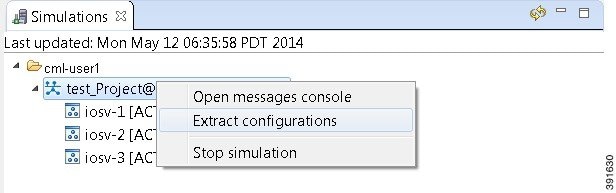
                  Figure 8. Simulations View Context Menu


                  A confirmation dialog box appears.
                  Step 2   Ensure that all external Telnet connections to the simulation are closed before proceeding.
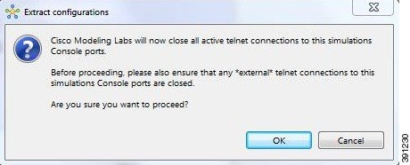
                  Note    You must close all external Telnet connections to the simulation before you can proceed.

                  Figure 9. Extract Configurations Dialog Box


                  Step 3   Click OK.

                  A dialog box appears.

                  Step 4   Click Run in Backgroud. When the extraction is complete, a message is displayed.
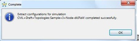
                  Figure 10. Extraction Complete Message


                  Note    The configuration information is extracted and saved in the filename.virl file that corresponds to the topology. For example, the file New_Topology that is running as a New_Topology-dkIFaW simulation has its configuration extracted to the file New_Topology.virl.
                  Step 5   Click OK.

                  What to Do Next

                  • (Optional) Stop the simulation.
                  • (Optional) Stop a single node in the simulation.