Validated Profile: Manufacturing (SD-Access) Vertical
Available Languages
Bias-Free Language
The documentation set for this product strives to use bias-free language. For the purposes of this documentation set, bias-free is defined as language that does not imply discrimination based on age, disability, gender, racial identity, ethnic identity, sexual orientation, socioeconomic status, and intersectionality. Exceptions may be present in the documentation due to language that is hardcoded in the user interfaces of the product software, language used based on RFP documentation, or language that is used by a referenced third-party product. Learn more about how Cisco is using Inclusive Language.
- US/Canada 800-553-2447
- Worldwide Support Phone Numbers
- All Tools
 Feedback
 Feedback
Note
If you are looking for the Manufacturing Non-Fabric Cisco Validated Profile, refer to Validated Profile: Manufacturing (Non-Fabric) Vertical to learn more.
Document Purpose and Usage
This guide describes a Cisco-validated profile (CVP) for a manufacturing production network that uses Cisco Catalyst Center and Cisco SD-Access. This guide is aligned with and generally follows design and implementation guidance in our industrial automation and converged plant-wide Ethernet (CPwE) Cisco-validated designs (CVDs). This guide helps deployment engineers make the best decisions for their network during deployment and configuration.
Target Audience
The audience for this guide is IT and operational technology (OT) professionals who deploy or manage manufacturing production networks. This guide serves as a validation reference for vendors, partners, system implementers, customers, and service providers involved in designing, deploying, or operating production systems.
Solution Overview
Production environments have evolved significantly over the past 15 years, moving away from proprietary and niche networking technologies to standard networking technologies and practices. Production networks are typically deployed and managed with a mix of IT and OT teams. Production environments have a unique set of requirements, including the need for network automation to consistently deploy large networks, enhanced network security for environments with little cybersecurity, highly available resilient network infrastructure to support critical operations, simplified monitoring for non-IT operators, and efficient troubleshooting. Design and deployment considerations help these critical areas, which are fundamental to the development of modern factories, production facilities, and warehouses.
Scope of the Document
This guide doesn’t offer step-by-step configuration guidance on the solutions that are recommended and available for manufacturing deployments. Use this guide as a reference to understand the common use cases and challenges and how Cisco SD-Access addresses those requirements.
Traditional Networks Versus Cisco SD-Access
The following sections discuss the challenges of traditional network architecture and how Cisco SD-Access can address them.
Challenges in Traditional Networks
Organizations deploying traditional network architectures face mounting challenges as users, devices, and types of devices continue to grow. Identifying, grouping, and analyzing the traffic of all the users and devices is a significant concern for organizations that want to protect their corporate infrastructure if a device is compromised. In traditional networks, the need for many VLANs and manual access control lists (ACLs) across multiple disparate devices becomes a recipe for manual misconfiguration disasters. As the business expands over time, more devices and locations are added, which increases complexity and the possibility for errors. New and more complex security rules must be manually updated across the enterprise.
When the organization adds a new branch to the enterprise, the network operations team must update the ACLs in the headquarter and branch locations. If an error is made during the update, the security policy becomes inconsistent and could result in a security breach. Network administrators must spend significant time planning and configuring network changes to ensure that every device is securely onboarded to the correct network segment. The traditional ways of building a network don’t cater to the requirements of an evolving network with ever-growing security concerns.
The Importance of Cisco SD-Access
Cisco SD-Access is built on an intent-based networking foundation that encompasses visibility, automation, security, and simplification. Using Catalyst Center automation and orchestration, network administrators can implement changes across the entire enterprise environment through an intuitive UI interface. Using the same controller, administrators can build enterprise-wide fabric architectures, classify endpoints for security grouping, create and distribute security policies, and monitor network performance and availability.
SD-Access secures the network at the macrosegmentation and microsegmentation levels using Virtual Routing and Forwarding (VRF) tables and Security Group Tags (SGTs), respectively. This approach is called multitier segmentation, which is not optimal in traditional networks. The security boundary is pushed to the very edge of the network infrastructure for wired and wireless clients.
The security contexts associated with users and devices are dynamically assigned when they authenticate their network connection. Cisco SD-Access is superior to traditional network deployments because of:
● Complexity reduction and operational consistency through orchestration and automation.
● Multitier segmentation, which includes group-based policies.
● Dynamic policy mobility for wired and wireless clients.
Greenfield Cisco SD-Access Fabric Guidelines
For guidelines and recommendations on a new deployment (greenfield deployment) of Cisco SD-Access fabric for a manufacturing network, continue to the following sections. These sections explain the SD-Access fabric components and the benefits that Cisco SD-Access solutions offer to address network requirements and challenges.
Traditional networks can be managed by Cisco Prime Infrastructure. They can also be managed with Catalyst Center. Catalyst Center automates, monitors, and gathers telemetry for traditional networks as well as SD-Access. If you have an existing network managed by Cisco Prime Infrastructure and you want to migrate to Catalyst Center, refer to the Cisco Prime Infrastructure to Cisco Catalyst Center Migration Guide.
Catalyst Center
Catalyst Center is a powerful management system that leverages Artificial Intelligence (AI) to connect, secure, and automate network operations. Catalyst Center simplifies management of Cisco Catalyst network infrastructure and ensures a consistent user experience across wired and wireless networks. It delivers enterprise-scale, secure, seamless, and reliable connectivity among users, applications, and things. Benefits include:
● Leverage AI to simplify and automate network operations, which helps reduce operational costs.
● Improve user experience with deep insights into business-critical applications and client health.
● Accelerate digital agility through business process automation using Cisco and third-party ecosystems.
● Secure the digital enterprise with intuitive security policy management, AI-enabled enforcement, and automated compliance checks.
● Drive sustainability by enabling smart buildings and optimizing Power over Ethernet (PoE) infrastructure.
The Catalyst Center platform is supported in different form factors as both physical and virtual appliances.
For details, refer to the Cisco Catalyst Center Data Sheet. Refer to also the Cisco Catalyst Center Installation Guides.
Cisco Identity Services Engine
Cisco Identity Services Engine (ISE) is a secure network access platform that enables increased management awareness, control, and consistency for users and devices accessing an organization's network. Cisco ISE is an integral and mandatory part of SD-Access for implementing network access control policy. Cisco ISE performs policy implementation, enabling dynamic mapping of users and devices to scalable groups, and simplifying end-to-end security policy enforcement. Catalyst Center is used as the pane of glass to manage and create scalable group tags (SGTs) and define their policies. Group and policy services are driven by Cisco ISE and orchestrated by Catalyst Center's policy authoring workflows. Policy management with identity services is enabled in an SD-Access network using Cisco ISE integrated with Catalyst Center for dynamic mapping of users and devices to scalable groups. This simplifies end-to-end security policy management and enforcement at a greater scale than traditional network policy implementations that rely on IP access lists.
Cisco ISE supports standalone and distributed deployment models. Multiple, distributed nodes can be deployed together to provide failover resiliency and scale. The range of deployment options allows support for hundreds of thousands of endpoint devices. A basic two-node Cisco ISE deployment is recommended for SD-Access single-site deployments with each Cisco ISE node running all services (personas) for redundancy.
For details, refer to the Cisco Identity Services Engine Administrator Guide. Refer to also the Cisco ISE Performance and Scalability Guide.
Cisco Catalyst 9000 Series Switches
Cisco Catalyst 9000 series switching offers flexible and highly scalable design options. Switches supported in different fabric roles offer secure, fast, and reliable connectivity to users and endpoints within the network. For details, refer to the Catalyst 9000 data sheet.
Cisco Catalyst Wireless LAN Controller and Access Point
Cisco Catalyst 9800 Series Wireless LAN Controllers (WLCs) and Access Points (APs) provide seamless network management and deployment in both on-premises and cloud for wireless clients. For the complete data sheet of Catalyst 9800 and Catalyst 9100 devices, refer to:
● Cisco Access Point and Wireless Controller Selector
Cisco SD-Access Fabric
Cisco SD-Access is the evolution from traditional campus LAN designs to networks that explicitly implement an organization's intent. SD-Access is a software solution used to automate wired and wireless campus networks. Fabric technology, an integral part of SD-Access, provides wired and wireless campus networks with programmable overlays and easy-to-deploy network virtualization, allowing a physical network to host one or more logical networks to meet the design intent.
In addition to network virtualization, fabric technology in the campus network enhances control of communications, providing software-defined segmentation and policy enforcement based on user identity and group membership. Software-defined segmentation is seamlessly integrated using Cisco TrustSec, providing microsegmentation for groups within a virtual network using SGTs. Using Catalyst Center to automate the creation of virtual networks with integrated security and segmentation reduces operational expenses and reduces risk. Network performance, network insights, and telemetry are provided through the Assurance and Analytics capabilities. Cisco SD-Access provides policy mobility for wired and wireless clients.
Fabric Architecture Overview
The following sections provide an overview of the Cisco SD-Access architecture and solution components.
Solution Components
The Cisco SD-Access solution is provided through a combination of Catalyst Center, Cisco ISE, and the wired and wireless device platforms, which have fabric functionality. The wired and wireless device platforms are used to create the elements of a fabric site. Catalyst Center software, including the SD-Access application package, runs on the Catalyst Center hardware appliance.
Operational Planes
● Control Plane: Messaging and communication protocol between infrastructure devices in the fabric.
● Data Plane: Encapsulation method used for the data packets.
● Policy Plane: Used for security and segmentation.
● Management Plane: Orchestration, assurance, visibility, and management.
In SD-Access, the control plane is based on Locator/ID Separation Protocol (LISP). The data plane is based on Virtual Extensible LAN (VXLAN). The policy plane is based on Cisco TrustSec. The management plane is enabled and powered by Catalyst Center.
Network Architecture
The SD-Access architecture is supported by fabric technology implemented for the campus, enabling the use of virtual networks (overlay networks) running on a physical network (underlay network) creating alternative topologies to connect devices. In SD-Access, the user-defined overlay networks are provisioned as VRF instances that provide separation of routing tables.
Fabric Roles
A fabric role is an SD-Access software construct running on physical hardware. For the hardware models supported for different fabric roles, refer to the Cisco SD-Access Compatibility Matrix.
● Control Plane Node
The SD-Access fabric control plane node is based on the LISP Map-Server and Map-Resolver functionality combined on the same node. The control plane node’s database tracks all endpoints in the fabric site and associates the endpoints to fabric nodes, decoupling the endpoint IP address or MAC address from the location (closest router) in the network.
● Edge Node
The SD-Access fabric edge nodes are the equivalent of an access layer switch in a traditional campus LAN design. Edge nodes provide endpoint registration locally and update the control plane node. Edge nodes provide the Anycast Layer 3 gateway for the hosts to connect to the fabric network and act as an authentication relay agent for the hosts.
● Intermediate Node
Intermediate nodes are part of the Layer 3 network used for interconnections among the devices operating in a fabric role, such as the interconnections between border nodes and edge nodes. These nodes provide IP reachability and physical connectivity and support the added MTU requirement to accommodate the larger-sized IP packets encapsulated with fabric VXLAN information.
● Border Node
Fabric border nodes serve as the gateway between the SD-Access fabric site and the networks external to the fabric. The border node can extend network virtualization from inside the fabric to outside of the fabric by using VRF-lite and VRF-aware routing protocols to preserve the segmentation. This may be a single switch, a switch with hardware stacking, or a StackWise Virtual deployment.
● Fabric in a Box
Fabric in a box is an SD-Access construct where the border node, control plane node, and edge node are running on the same fabric node. This may be a single switch, a switch with hardware stacking, or a StackWise Virtual deployment.
For more information, refer to the Cisco Catalyst 9000 Platform StackWise Virtual White Paper.
● Extended Node
SD-Access extended nodes offer the ability to extend the enterprise network by providing connectivity to noncarpeted spaces of an enterprise, commonly called the extended enterprise. Extended nodes offer a Layer 2 port extension to a fabric edge node while providing segmentation and group-based policies to the endpoints connected to these switches. For a detailed extended node design, refer to the Cisco SD-Access Solution Design Guide.
● Fabric Wireless Controller and APs
Fabric wireless controllers and non-fabric wireless controllers provide AP image and configuration management, client session management, and mobility services. Fabric wireless controllers provide added services for fabric integration, such as registering MAC addresses of wireless clients into the host tracking database of the fabric control plane nodes. The fabric-mode APs are Cisco Wi-Fi 6 (802.11ax) and 802.11ac Wave 2 APs associated with the fabric wireless controller that have been configured with one or more fabric-enabled SSIDs. Fabric-mode APs support the same wireless media services that traditional APs support, such as applying AVC, QoS, and other wireless policies.
For information on wireless operations and communications with SD-Access wireless, fabric wireless controllers, and fabric APs, refer to the SD-Access Wireless Design and Deployment Guide.
● SD-Access Embedded Wireless
Wireless controller functionality without a hardware wireless controller in distributed branches and small campuses can be achieved with the Cisco Catalyst 9800 Embedded Wireless Controller for Catalyst 9000 Series Switches as a software package. The Cisco Catalyst 9800 Embedded Wireless Controller for Catalyst 9000 Series Switches is supported for SD-Access deployments with the following topologies:
◦ Cisco Catalyst 9000 Series switches functioning as collocated border and control plane.
◦ Cisco Catalyst 9000 Series switches functioning as an edge node when the border and control plane nodes are on a routing platform.
◦ Cisco Catalyst 9000 Series switches functioning as fabric in a box.
● Transit and Peer Network
Transit and peer network are SD-Access constructs that define how Catalyst Center automates the border node configuration for the connections between fabric sites or between a fabric site and the external world. This connectivity may be MAN, WAN, or internet. The two distinct types of transit networks available in the SD-Access fabric are SDA transit and IP transit to connect distributed campuses and the external network.
● Transit Control Plane Nodes
Transit control plane nodes are a fabric role construct supported in SD-Access for distributed campus. It works in the same manner as a site-local control plane node except it services the entire fabric. Transit control plane nodes are needed only when using SD-Access transits. For details, refer to the Software-Defined Access for Distributed Campus Deployment Guide.
You can find detailed information on Cisco SD-Access components and architecture here.
High Availability
Cisco SD-Access High Availability (HA) refers to the design and implementation of features and mechanisms that ensure the continuous and reliable operation of the SDA solution. HA is crucial for minimizing downtime and maintaining network functionality, especially in critical environments.
Cisco SD-Access HA aims to create a robust and resilient network infrastructure by combining redundancy, failover mechanisms, load balancing, health monitoring, and fast convergence. These features collectively contribute to ensuring continuous and reliable network services, even in the face of unexpected events or hardware or software failures.
The manufacturing SDA network incorporates the following HA components:
● Three-Node Catalyst Center Cluster
Catalyst Center is configured as a three-node cluster. This clustering approach enhances scalability, load distribution, and provides failover capabilities, ensuring continuous operation in the event of a node failure.
● Distributed Cisco ISE Cluster
Cisco ISE has a highly available and scalable architecture that supports standalone and distributed deployments. In a distributed environment, redundant Policy Administration Node (PAN), monitor, and Policy Service Node (PSN) are deployed. You can configure one primary administration Cisco ISE node to manage the secondary Cisco ISE nodes that are deployed in the network.
● FTD Firewall Failover Pair
Firepower Threat Defense (FTD) firewall is deployed in a failover pair configuration. If one firewall fails, the standby firewall assumes the active role, preventing disruptions in network security services.
● Catalyst 9800 Series Wireless Controller SSO HA
Catalyst 9800 Series Wireless Controller is configured with Stateful Switch Over (SSO) HA. This ensures a smooth transition in case of a failure, maintaining wireless network services without interruption.
● Catalyst 9500 SVL Pair for Border and Control Plane
A pair of Catalyst 9500 Series switches is configured in StackWise Virtual Link (SVL) mode to handle border and control plane functions. This redundancy enhances the reliability of these critical network components.
● Catalyst 9600 Quad SUP SVL Pair for Border and Control Plane
For high-capacity requirements, a pair of Catalyst 9600 Series switches with Quad Supervisor Engines (SUPs) is configured in SVL mode to serve as the border and control plane node, providing both redundancy and performance.
● Catalyst 9300 Stacking Switch as Fabric Edge
Catalyst 9300 Series switches are configured in a stacking arrangement. Stacking allows these switches to operate as a single logical unit, providing high availability and simplifying management.
● Catalyst 9400 Dual Supervisor as Fabric Edge
Catalyst 9400 Series switches are equipped with dual SUPs to ensure HA at the fabric edge. The dual SUPs provide redundancy and facilitate uninterrupted operation in case of a SUP failure.
These mechanisms collectively contribute to a resilient and highly available network infrastructure in the Catalyst Center SD-Access environment, minimizing the impact of potential failures and enhancing the overall reliability of the network.
Compatibility Matrix
Catalyst Center provides coverage for Cisco enterprise switching, routing, and mobility products. For a complete list of Cisco products supported, refer to:
● Cisco Catalyst Center Compatibility Matrix
● Cisco SD-Access Compatibility Matrix
Manufacturing Profile Deployment
This section offers design guidance for the manufacturing space, focusing on the requirements and how Cisco SD-Access is used in this vertical to have a simple, secure, and flexible network.
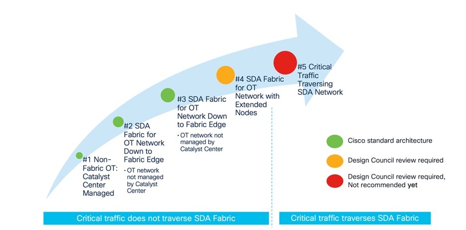
The evolution of SDA in manufacturing is visually represented in the following diagram. The initial stage involves managing a non-SDA network using Catalyst Center, reaping the benefits of automation and assurance. Step 2 illustrates the SDA network extending to the fabric edge, with the OT access network connected below but remaining outside the fabric's management purview, independent of Catalyst Center.
Step 3 includes industrial switches in the management ambit of Catalyst Center. Industrial switches can be integrated as extensions of the fabric, functioning as extended nodes or policy extended nodes. However, this deployment option necessitates design council approval due to the likelihood of requiring templates that demand scrutiny for conflicts with the intent-based configuration.
Deployment models 2, 3, and 4 incorporate the SDA network, but critical traffic such as profinet and Ethernet/IP remains localized below the fabric edge and does not traverse the network. In Step 5, critical traffic traverses the SDA fabric. It's important to note that this deployment is currently not recommended.
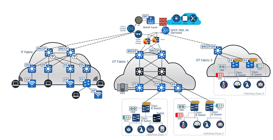
The topology for the manufacturing vertical includes a three-node Catalyst Center cluster to manage one IT network site, one medium-scale OT site, and one small OT network. Cisco SD-Access Transit is deployed to connect these networks. The following figure illustrates the logical topology of the manufacturing vertical solution test bed.
The test bed setup has the following components:
● OT Fabric site 1 has dual borders, dual dedicated control plane nodes, dual wireless controllers, 10 fabric edges, and 20 extended nodes.
● IT network site has dual collocated border and control plane nodes, a wireless controller, fabric edges, and extended nodes.
● OT Fabric site 2 is a small site that has fabric in a box on hardware stacking with an embedded wireless controller and extended nodes.
● SD-Access Transit is implemented with dual Transit Control Plane nodes. IT network borders are configured to provide internet access to other OT sites via SD-Access Transit.
Large Manufacturing - Multisite IT and OT Deployment
Business Outcomes and Challenges
Manufacturing networks are widespread, diverse, and complex with unique challenges. These networks require elevated levels of security, resilience, and regulatory compliances. The following section explains the most critical capabilities of a manufacturing network to achieve business outcomes.
Financial
Streamline expenses and boost earnings through the automation of deployment across hundreds of sites while minimizing the need for onsite network operations whenever feasible.
Large-Scale Multisite Deployments
Manufacturing plants are typically large multisite deployments with thousands of sites across vast geographic regions. It is an enormous challenge to deploy and manage such large networks box-by-box or site-by-site with onsite network management teams. Manufacturing network engineers demand automation to perform complex site deployments with minimal manual work.
Automation and Monitoring
Manufacturing facilities have large, complex networks with numerous devices and configurations. Automation streamlines network provisioning, configuration changes, and maintenance tasks, reducing downtime, workloads, and the risk of human error. For any network automation solution targeting manufacturing floors, scalability is essential due to the large number of network devices that facilitate network connectivity in these environments.
Security
Today's OT network sometimes provides limited segmentation capabilities. Many networks are VLAN based. When deeper segmentation is needed, many organizations create physically separate OT networks. There is a need for logical segmentation with the strength of physical separation but the simplicity of a single network. Segmentation is sometimes used as a means to help address cybersecurity. If segmentation is instantiated by IP ACLs, it can become difficult to scale, troubleshoot, and maintain over time in all but the most trivial deployments.
Compliance Regulations
Manufacturing systems need to protect extremely sensitive financial records and customer information, with strict government regulations. For example, the payment card industry (PCI-DSS) standards include mandates such as data encryption in flight, security mandates for storing customer data, and tracking and monitoring network resources and cardholder data.
Finally, given that different departments and guests all share the same network infrastructure, every group must be isolated from one another and restricted to only the resources they are allowed to access. At the same time, these diverse groups of users and devices need access to shared services.
Experience
Enhance user and customer experiences by leveraging modern technologies to enable and support key business capabilities.
Handling Silent Hosts
One of the biggest problems in an OT network is the variety of endpoints on the manufacturing floor. Some devices are assigned with static IP addresses and remain untouched for years. Among these, some endpoints belong to the category of silent hosts, which generally require reception of an Address Resolution Packet (ARP) broadcast packet to come out of silence.
High Sensitivity to Quality of Service
In addition to worrying about security, compliance, and availability, a slow and QoS-disparate network can lead to poor customer satisfaction and monetary losses. When it comes to production stations, which are overly sensitive to delays, low latency and consistent QoS are mandatory to fulfill the organization's needs.
Operational
Maximize productivity and ease digital transformation initiatives while effectively managing reputation and enhancing brand value.
High Availability
Manufacturing operations often run continuously. Any disruption in the network can result in production downtime and financial loss. HA ensures that the network is operational in the event of hardware failures, software issues, connectivity issues, or other disruptions, reducing the production downtime. Ensuring the uptime of industrial automation and control systems within the manufacturing network requires a robust and resilient network.
Centralized and Consistent Policy Management
With exponential growth in the number of endpoints connecting to the network and the spanning of large factories across the globe, there is a need to manage security policy in different geographical regions.
This leads to management complexity, because rules may be driven by local laws. There is a need to simplify the grouping of users and devices so that security policies can be managed intuitively.
Solutions to Manufacturing Business Outcomes
The following solutions help achieve business outcomes for manufacturing network deployments.
Uncarpeted Space Extension
In the manufacturing world, devices in OT networks are likely to be placed in uncarpeted, rugged locations. In this case, Cisco Industrial Ethernet (IE) switches are used as extended nodes. Cisco SD-Access extended nodes enable mobility by offering a Layer 2 port extension and increasing the port density to existing fabric edge nodes, while also providing segmentation and group-based polices to the endpoints connected to these switches. Catalyst Center provides a zero-touch, plug-and-play automated workflow to discover, provision, and add extended nodes to the fabric.
Catalyst Center has different support options for extended nodes: classic extended nodes (ENs) and policy extended nodes (PENs). In addition to the operation and management provided by classic extended nodes, PENs directly support SGT policy enforcement with SGACLs. This local support of SGACLs provides direct east-west traffic enforcement on PENs.
Extended nodes are connected to a single fabric edge switch through an 802.1Q trunk port. This port can be deployed as an EtherChannel if two or more links are aggregated at the upstream fabric edge. Catalyst Center automates the trunk and the creation of the EtherChannel. After extended nodes have been onboarded through the workflow, endpoints (including fabric-mode APs and other Power over Ethernet [PoE] devices) can connect directly to the extended node, expanding the wired and wireless services to uncarpeted spaces as needed. For details, refer to the Cisco Extended Enterprise Non-Fabric and SD-Access Fabric Design Guide.
Efficient Onboarding of New Switches Using Cisco Plug and Play
In a manufacturing plant, the swift onboarding of new switches is paramount for seamless operations. The process must be:
● Fast: New switches must be onboarded quickly, ensuring operational readiness within minutes.
● Simple: Operators without a networking background must be able to execute the onboarding process.
● Scalable: The process must be capable of replication across hundreds of switches.
● Consistent: Adhering to the prescribed workflow must guarantee uniform configuration and prevent human errors.
The Catalyst Center onboarding process uses Zero Touch Deployment (ZTD) through Plug and Play (PnP). PnP facilitates the automated configuration of new, unconfigured devices within the network, leveraging the network profile of the site. Sites group devices by physical location or function in the network.
For Cisco industrial switches running IOS or IOS-XE software, an embedded PnP agent communicates with the PnP deployment server. This agent operates on devices without a startup configuration, such as those newly powered on or reset to factory defaults. The agent discovers the PnP deployment server through DHCP or DNS on Catalyst Center. The PnP agent initiates communication with the PnP server, downloading essential software and device configurations.
When an unconfigured device connects to the network and contacts Catalyst Center, an entry is created for the device, placing it in an unclaimed state until claimed by an administrator. Alternatively, devices can be added to Catalyst Center before installation by entering serial numbers and device families. After connecting, the devices can be claimed to a designated site and configured with the predetermined software image and configuration based on site settings.
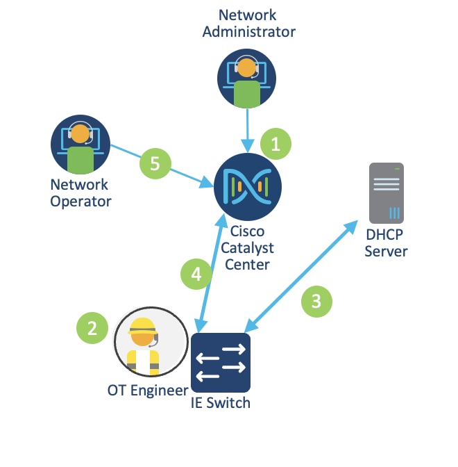
The following figure shows the PnP provisioning workflow.
1. A network administrator creates a site hierarchy in Catalyst Center, configures site properties, adds provisioning templates, and defines golden images.
2. An OT engineer connects the industrial switch to the network and powers on the device.
3. The switch uses DHCP to obtain an IP address and discover the PnP server IP address (Catalyst Center).
4. The industrial switch connects with Catalyst Center.
5. An operator claims the device on Catalyst Center. During the claiming process, Catalyst Center:
◦ Installs the golden image.
◦ Issues the configuration, including licensing.
◦ Adds the device to the Cisco ISE and Catalyst Center inventories.
Adding Configured Devices to Catalyst Center
While the PnP process offers an efficient approach to switch onboarding, certain scenarios may necessitate alternative methods. Examples include:
● Offline New Switch Provisioning: In specific situations, switches require provisioning before they can connect to the network. This is especially relevant in industrial automation environments, where switches may need configuration before gaining network connectivity. As the PnP process relies on network connectivity for configuration, a different approach is needed for switches provisioned offline.
● Switch Configured Outside the Manufacturing Facility: In certain cases, system integrators configure switches before their arrival at the manufacturing facility. This practice streamlines the onboarding process, as switches arrive preconfigured and ready for immediate deployment.
● Brownfield Deployment: Brownfield refers to devices integrated into existing sites with established configurations. When dealing with brownfield deployments, network devices are added to Catalyst Center through a process called discovery.
The discovery feature is used to add network devices to Catalyst Center. This feature performs a scan of devices within the network and sends a list of discovered devices that is then seamlessly integrated into the inventory.
Various methods can be employed for discovery, including IP address range, Cisco Discovery Protocol (CDP), or Link Layer Discovery Protocol (LLDP). For this guide, the IP address range is used. During a discovery task, configuration of CLI and SNMP read credentials are required on Catalyst Center.
Site Assignment and Network Assurance
During device discovery, the option to assign the device to a specific site is available. By doing so, Catalyst Center pushes telemetry configurations to provide network assurance to the newly added device.
Cisco Firepower 9300 as the SD-Access Fusion Device
Network segmentation plays a crucial role in safeguarding vital business assets. In SD-Access, security is seamlessly integrated into the network through segmentation. Segmentation involves separating specific groups of users or devices from others for security reasons. SD-Access employs two key types of segmentation: macrosegmentation and microsegmentation.
Macrosegmentation (Virtual Networks)
Macrosegmentation in SD-Access entails breaking down a single large network with a unified routing table into numerous smaller logical networks (segments or virtual networks). This process provides isolation between segments, reduces the attack surface, and introduces enforcement points between them. SD-Access facilitates secure network deployment for environments by offering a straightforward approach to understanding, designing, implementing, and supporting networks. In the SD-Access fabric, the VXLAN network identifier (VNI) field carries information identifying the virtual network and SGT within the VXLAN-GPO header.
Macrosegmentation logically divides a network topology into smaller virtual networks using a unique network identifier and separate forwarding tables. This is realized as a VRF instance on switches or routers, referred to as a virtual network in Catalyst Center.
A virtual network within the SD-Access fabric is a logical network instance providing Layer 2 or Layer 3 services and defining a Layer 3 routing domain. The VNI field in the VXLAN header carries information identifying the virtual network within the SD-Access fabric, supporting both Layer 2 (Layer 2 VNI) and Layer 3 (Layer 3 VNI) segmentation.
LISP is employed within the SD-Access fabric to provide control plane forwarding information. The LISP instance ID ensures unique address spaces in the control plane, supporting virtualization. Externally, at the SD-Access border, virtual networks directly map to VRF instances, which can extend beyond the fabric.
This segmentation approach enhances security, simplifies network management, and enables scalable deployments in complex environments.
Microsegmentation (SGT)
Cisco Group-Based Policy simplifies the way we manage security and flexibility in our network. Instead of dealing with complex technical details, we organize devices into groups based on their roles. These groups can be used across different parts of the network, making it easier to set up and manage security rules.
Think of it like sorting devices into user-friendly categories, such as the type of device or its role in the network. Unlike traditional methods that rely on complicated IP addresses, our approach uses these simple categories to define security rules. This makes it easier to control and manage security measures.
Scalable groups, also known as security groups, provide information about the devices, like their role, the applications they use, or even the threat level they pose. This additional insight helps streamline the setup of firewall rules, web security policies, and access controls in various network devices.
Cisco Group-Based Policy is straightforward to enable and manage, unlike older methods that involve complex VLAN-based segmentation.
In SD-Access, network segmentation occurs at both macro and micro levels using virtual networks and SGTs. Virtual networks act as isolated domains within the SD-Access fabric, providing macrosegmentation between different virtual networks and allowing communication among devices within each virtual network. By default, devices within a virtual network can communicate with each other, but to facilitate communication between different virtual networks, an external device like a fusion router or firewall is necessary to handle inter-VRF forwarding. On a finer scale, microsegmentation is achieved through SGTs, enabling more granular control over communication within a virtual network. This approach ensures a structured and secure network environment within SD-Access.
A fusion device in SD-Access facilitates VRF leaking across fabric domains, enabling host connectivity to shared services like DHCP, DNS, NTP, Cisco ISE, Catalyst Center, and wireless LAN controllers in the data center or service block. While this role can be performed by various devices, this guide focuses on the Cisco FTD routed mode firewall as a fusion device. To provide shared services to all virtual networks in the campus, BGP peerings are created between border nodes and the FTD firewall. The fusion device leaks fabric VRF subnets, requiring access to shared services, into the Global Routing Table (GRT) or a shared services VRF, and conversely.
This validation uses a virtual router on Cisco Firepower firewall for control plane and data plane separation. Virtual routers maintain separate routing tables for groups of interfaces on a single firewall.
REP Ring
Industrial automation processes rely on the availability and uptime of the Industrial Automation Control Systems (IACS) applications. To ensure the continuity of these systems, a resilient and robust network design is crucial. By implementing a LAN architecture that enhances resilience and hardening of standard Ethernet and IP-converged IACS networking technologies, the overall equipment effectiveness (OEE) can be improved, minimizing the impact of failures, and reducing the mean-time-to-repair (MTTR).
A resilient design provides alternative paths in the event of equipment or link failure. Within the cell/area zone, network redundancy is achieved by using a star or ring topology for uplinks from the edge switching platforms. To prevent loops within redundant links, a resiliency protocol must be deployed. Resilient Ethernet Protocol (REP) is an example protocol that prevents looping within a ring topology.
REP is a Cisco proprietary protocol that offers an alternative to Spanning Tree Protocol (STP) for controlling network loops, handling link or node failures, and avoiding convergence time. It operates a single redundancy instance per segment or physical ring. A REP segment consists of ports connected to each other with a unique segment ID. Each segment includes standard segment ports and two user-configured edge ports. The network segment terminates at a neighboring Cisco IE access switch or distribution switch, with the terminating port referred to as the edge port. Loop prevention within the ring is maintained by blocking one port in the segment, known as the alternate port. In the event of a segment failure, the alternate port transitions to a forwarding state, allowing traffic to flow through the alternate path, bypassing the network failure.
To learn about resiliency protocols in industrial automation, refer to Networking and Security in Industrial Automation Environments.
Catalyst Center provides the workflow to create and deploy a REP ring on the SDA fabric site where the IE switches are connected to the fabric edges and onboarded as two daisy chains of extended nodes. To set up REP ring automation in Catalyst Center:
Step 1. Click the menu icon and choose Workflows > Create REP Ring.
Alternatively, navigate to the Fabric Site topology view, select the Fabric Edge node or the FIAB node on which you want to create the REP ring, and click Create REP Ring under the REP Rings tab.
Step 2. Choose a fabric site from the drop-down list and click Next.
Step 3. Choose a fabric edge node in the topology view and click Next.
Step 4. Choose the extended nodes that connect to the fabric edge node and click Next.
You can choose two extended nodes to connect to the fabric edge node.
Step 5. Review and edit (if required) your fabric site, edge node, and extended node selections and click Provision.
Step 6. The REP Ring Summary window displays the details of the REP ring that is created along with the discovered devices. Click Next.
Step 7. After the creation of the REP ring, a success message is displayed.
Step 8. To verify the creation of the REP ring, go to the fabric site window and click the fabric edge node. In the slide-in pane, under the REP Ring tab, view the list of all REP rings that exist on that edge node.
Zero-Loss Redundancy: Dual Fabric with PRP
As OT networks become critical for the functioning of an organization, it is critical to provide resiliency all the way to full redundancy options for networks. These schemes for redundancy can take from several milliseconds to several seconds for the network to recover and traffic to flow again. If the quality management system like SAP for a manufacturing floor is down, the manufacturing line is down. If the network is impacted, chances are high that the plant is down, costing financial losses per second.
To recover from network failures, redundancy can be provided by network elements connected in mesh or ring topologies using protocols like RSTP, REP, or MRP. A network failure causes some reconfiguration in the network to allow traffic to flow again, typically by opening a blocked port. Manufacturing customers have stringent requirements for zero packet loss.
Parallel Redundancy Protocol (PRP) is defined in the International Standard IEC 62439-3. PRP is designed to provide hitless redundancy (zero recovery time after failures) in Ethernet networks. PRP uses a different scheme, where the end nodes implement redundancy (instead of network elements) by connecting two network interfaces to two independent, disjointed, parallel networks (LAN-A and LAN-B). Each Dually Attached Node (DAN) has redundant paths to all other DANs in the network.
There is a solution to leverage PRP in SDA networks to achieve zero packet loss by creating a redundant SDA fabric and connecting the extended nodes to both the main and redundant sites. The following sample topology contains two SDA fabric sites.
This implementation is achieved through Catalyst Center using extended node onboarding and CLI templates to push the PRP-specific configuration on the extended nodes.
Step 1. Connect the extended node via the regular PAgP port-channel to Fabric1, where it is onboarded by the LAN Automation process as a policy extended node:
interface Port-channel1
description Extended2
switchport mode trunk
!
interface GigabitEthernet1/0/11
switchport mode trunk
cts manual
policy static sgt 8000 trusted
channel-group 1 mode desirable
Step 2. After the IE switch is onboarded successfully, the downlink port on Fabric2 edge node is configured as PAgP trunk port from the Catalyst Center GUI:
interface Port-channel1
switchport mode trunk
device-tracking attach-policy IPDT_POLICY
!
interface GigabitEthernet1/0/13
switchport mode trunk
channel-group 1 mode desirable
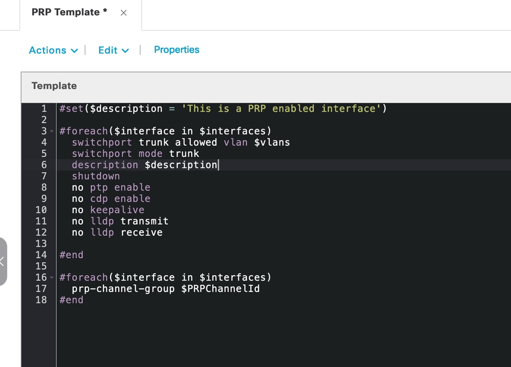
Step 3. After the edges from both fabric sites are connected to the IE switch and provisioned, the PRP configuration is applied on the uplink ports on the IE switch using Catalyst Center template provisioning. The following sample Velocity template shows the PRP configuration:
OT Network Visibility with Cisco Cyber Vision
Lack of visibility is a common challenge in industrial networks. When networks are old, widely dispersed, and involve many contractors, operators often do not have an accurate inventory of what is on the network. Without this visibility, they have limited ability to build a secure communications architecture. A lack of visibility also means operators are unaware of which devices are communicating to each other or even of communications reaching industrial devices from the outside. The lack of visibility leads to a lack of segmentation or control.
OT visibility is a technology that all personas in OT environments can leverage. OT operators gain benefit of process-level visibility to identify and troubleshoot assets residing on the plant floor. IT operators gain insight into device communication patterns to help inform policy and improve network efficiency. Security teams gain insight into device vulnerabilities and deviations from normal device behaviors. Visibility is important to:
● Identify all assets and group them into zones.
● Visualize data that flows through the conduits between zones.
● Give a clear view of which source data is coming in through external networks.
Cisco Cyber Vision addresses the visibility needs of industrial networks. It is built on an edge architecture comprising multiple sensor devices that perform deep packet inspection, protocol analysis, and intrusion detection within the industrial network. The Cyber Vision Center serves as an aggregation platform, storing data from the sensors and offering a user interface, analytics, behavioral analysis, reporting, APIs, and more. For information, refer to Industrial Automation Security Design Guide 2.0.
Cisco Cyber Vision sensors are deployed in switches managed by Catalyst Center. It is possible to use templates to prepare the industrial switch for sensor installation via Catalyst Center.
Validated Solution Use Cases
The following sections describe some of the important use cases validated for manufacturing networks. Organizations can construct their IT/OT infrastructure with certainty, knowing that these designs have undergone thorough testing and are tailored to effectively fulfill business requirements.
Day-0 Operation Use Cases
Bring up a new manufacturing site with wired devices in Catalyst Center:
● Provision a network through LAN automation.
● Discover devices and topologies.
● Provision configurations.
● Create a fabric.
● Add the edge devices and extended nodes to the fabric.
● Integrate with Cisco ISE for device and client authentication, profiling for wired and wireless.
● Manage and deploy wireless controllers and APs.
● Onboard devices via Plug and Play for network devices and APs.
● Manage network settings for multiple sites using Cisco Catalyst for shared services.
Deploy wireless networks for an OT space in Catalyst Center:
● Upload a floor map to a Catalyst Center site.
● Add new APs with Plug and Play, assign new APs to the new site location, and locate them on the floor map.
● Create and provision wireless profiles and policies on the new site.
Day-1 Operation Use Cases
Manage and provision wireless networks with Catalyst Center:
● Modify wireless settings and network profiles.
● Create new SSIDs and update existing SSIDs.
● Update profiles, tags, AP zones, and so on.
● Onboard new APs with Plug and Play.
● Replace or refresh APs through Catalyst Center workflows.
● Change AP locations and reprovision APs.
Manage and provision network security with Catalyst Center:
● Monitor threats and manage rogue rules and Advanced Wireless Intrusion Prevention System (aWIPS) profiles.
● Configure guest access Wi-Fi with traffic segmentation.
● Apply MAC Authentication Bypass (MAB) or Dot1x authentication for AP onboarding.
● Configure wired and wireless endpoint security policies, such as Dot1x authentication and a preshared key (PSK).
● Scan network devices and provide security advisories.
Network Management, Monitoring, and Troubleshooting Use Cases
Manage network inventory with Catalyst Center:
● Onboard devices through Plug and Play.
● Discover devices by IP address or Cisco Discovery Protocol (CDP).
● Replace broken devices.
● Run compliance checks.
● Move devices between locations.
● Manage device certificates.
● Manage password changes.
Manage device configurations with Catalyst Center:
● Use device templates to deploy new configurations.
● Track device configuration changes.
● Use Assurance audit logs to monitor errors that occur during configuration.
Manage device software and schedule upgrades with Catalyst Center:
● Upgrade network routers and switches, including SLV pairs and stack switches.
● Upgrade wireless devices, including wireless controller SSO pairs and C9800-CL.
● Schedule AP rolling upgrade.
● Generate software image management (SWIM) report.
Monitor network and device health, client endpoints, and network utilizations with Assurance:
● Monitor network device health and utilizations.
● Monitor system health for each location.
● Monitor network services, such as AAA and DHCP.
● Monitor wireless controllers and APs.
● Monitor the number of wired and wireless clients and details.
Troubleshoot network issues with Catalyst Center:
● Access devices and run CLI commands through SSH.
● Compare device configuration changes.
● Run a path trace and discover any link failures.
● Analyze the root cause of high CPU utilization.
● Check audit logs for troubleshooting applications or device public key infrastructure (PKI) certificates.
System and Network Robustness Use Cases
Verify system-level resiliency during the following events:
● Wireless controller SSO.
● Single AP failure.
Verify system-level resiliency during the following events:
● SVL border and control plane failover.
● SVL border and control plane link failure.
● Stack access switch member failure.
● Link failure between the distribution and fabric edge.
● Link failure between the distribution and fabric border and control plane node.
Verify system-level resiliency during the following events:
● Policy Service Node (PSN) failure.
● Policy Administration Node (PAN) failover.
● Cisco ISE PSN change.
● Cisco ISE upgrade.
Scale Matrix
The solution is verified with the scale numbers listed in the following table. For the software and hardware compliance, refer to the Cisco Catalyst Center Data Sheet.
| Attribute |
SDA Scale Numbers |
| Devices in inventory |
5000 |
| Devices per fabric site |
1000 |
| Buildings and floors |
2000 |
| VNs per fabric site |
64 |
| IP pools per fabric site |
500 |
| Wireless controllers per fabric site |
2 |
| Fabric sites |
500 |
| APs in inventory |
12,000 |
| Endpoints |
100,000 (80,000 wired; 20,000 wireless) |
| SSIDs |
10 |
| SGTs |
4000 |
| IE devices in a REP ring |
18 |
Note: The Catalyst Center on ESXi virtual appliance supports the same scale and performance as a 44-core physical appliance for small-scale environments. Refer to the Cisco Catalyst Center on ESXi Deployment Guide.
Hardware and Software Specifications
The solution is validated with the hardware and software listed in this table. For a complete list of supported hardware and software, refer to the Cisco Catalyst Center Compatibility Matrix.
| Role |
Hardware platform |
Software version |
Software version |
| Catalyst Center |
DN3-HW-APL-XL |
2.3.7.9 |
2.3.7.9 |
| Catalyst Center |
DNA-SW-OVA |
2.3.7.9 |
2.3.7.10 |
| Identity Management, RADIUS Server |
SNS-3695-K9 |
Cisco ISE 3.3 Patch 4 |
Cisco ISE 3.4 Patch 3 |
| Cisco Wireless Controller |
C9800-80-K9, C9800-CL |
17.9.6, 17.12.5 |
17.12.6 |
| Cisco SD-Access Fabric Edge |
C9200, C9300, C9400 |
17.9.6a, 17.12.5, 17.15.3 |
17.12.6, 17.15.4d, 17.18.3 |
| Fabric Border/Control Plane |
C9500-40x/C9606R |
17.9.6a, 17.12.5, 17.15.3 |
17.12.6, 17.15.4d, 17.18.3 |
| Cisco Firepower Threat Defense Security Appliances |
FPR9300, FPR4100 |
7.2 |
7.2 |
| Cisco Secure Firewall Management Center |
FMC Virtual |
7.2 |
7.2 |
| Cisco Industrial Ethernet IE3400 Extended Node |
Cisco Catalyst IE3400 Rugged Series |
17.12.4 |
17.15.3 |
| Cisco Cyber Vision |
Center and Sensor |
4.4 |
5.0.1 |
● Catalyst Center on ESXi has limitations and restrictions. Refer to the Cisco Catalyst Center on ESXi Release Notes.
● Unlike the Catalyst Center appliance platform, you can’t connect VMs to create three-node clusters. To achieve HA, you must use VMware vSphere. Refer to the Cisco Catalyst Center on ESXi Administrator Guide.
Technical References
● Cisco SD-Access Solution Design Guide (CVD)
● Cisco Catalyst Center Administrator Guide
● Cisco Catalyst Center for Industrial Automation Design Guide
● Support for Multiple Cisco Catalyst Center Clusters with a Single Cisco ISE System
● Cisco Catalyst Center Release Notes
● Cisco Catalyst Center Security Best Practices Guide
● Software Defined Access (SDA) Provisioning Best Practice Guide