Cisco DNA Center implements Software-Defined Access in two ways:
-
Virtual Networks (VNs) provide macro-level segmentation. For example, to separate IoT devices from the corporate network.
-
Group-based policies provide micro-level segmentation. For example, to control what types of network traffic to permit or
deny between engineering and HR groups.
The Group-based access control policy menu allows you to monitor and manage your scalable group access policies. These policies
provide the following benefits:
-
Rich identity-based access control functionality with network automation and assurance benefits.
-
Granular access control.
-
Scalable groups apply to all virtual networks, which simplifies policy management.
-
Policy views help you to understand the overall policy structure, and create or update required access control policies.
-
Eliminates the need to switch between different applications to manage scalable groups and define protected assets.
-
Provides enhanced features for deploying enterprise-wide access control policies.
-
Restricts lateral movement of threats like ransom ware before you have identity or Network Admission Control (NAC) applications
in place.
-
Provides an easy migration path to Cisco Identity Services Engine (Cisco ISE) for users who are using third-party identity applications, but want to move to Cisco ISE.
For information about creating IP pools, sites, and virtual networks in Cisco DNA Center, see the Cisco Digital Network Architecture Center User Guide.
For information about configuring Cisco DNA Center for Cisco ISE, see the Cisco Digital Network Architecture Center Installation Guide.
For information about configuring Cisco ISE for Cisco DNA Center, see the Cisco Identity Services Engine Administrator Guide.
First define the scalable groups and contracts, then create access control policies. The access control policies define which
network traffic can pass from a source scalable group to a destination scalable group.
-
Scalable Group: A classification category, to which you can assign users, network devices, or resources. Scalable groups are used in access
control policies. You can associate scalable groups with virtual networks based on your organization's network configuration,
access requirements, and restrictions.
-
Contract: An access contract is a set of rules that controls the type of network traffic that is allowed to pass between the source
and destination scalable groups. In other words, a contract is a traffic filter definition. Access contracts define the actions
(permit or deny) performed when the traffic matches a network application, protocol, and port. The default action is to use
the Catch All rule when no other rules match.
-
Group-Based Access Control Policies: A group-based access control policy identifies a specific source and destination group pair and associates an access contract.
The access contract specifies what types of traffic are permitted or denied between the source group and the destination group.
These policies are unidirectional.
Scalable groups and access contracts are the basic building blocks of access control policy. While creating the access control
policy, you can use the scalable groups and contracts that you have created before or create new scalable groups and contracts
while creating the policy. If you want to specify the network resources that can be accessed from a specific source group,
you can create an access control policy with a single source and multiple destination groups. On the other hand, if you want
to specify the source groups that are permitted to access a particular network resource, you can create an access control
policy with a single destination and multiple source groups. For example, if you want to specify the network resources that
can be accessed by the users associated with the "contractors" source scalable group, you can create an access control policy
with a single source and multiple destination groups. If you want to specify the source groups that are permitted to access
the "Finance Servers" destination scalable group, you can create an access control policy with single destination and multiple
source groups.
You can specify the default policy to use when no contract is specified for a source and destination scalable group combination.
The default policy is Permit. You can change this policy to Deny, Permit_IP_Log, or Deny_IP_Log, if necessary. You can set the default policy based on your network type, an open or closed network.

Note |
We recommend that you change the default policy from "Permit" to "Deny" only if you have created explicit policies to permit
necessary network traffic for all your network infrastructure devices. Failure to do so can result in loss of network connectivity.
|
List View
Click the List icon at the top right of the Group-Based Access Control window to launch the List view.
-
Source View: This view displays a list of existing policies organized based on the source groups. You can expand each row to view the
specific source-destination policy details.
-
Destination View: This view displays a list of existing policies organized based on the destination groups. You can expand each row to view
the specific source-destination policy details.
To see which destination groups are available from a specific source group, use the Source view. To see which source groups are permitted to access a particular destination group, use the Destination view. For example, to see which destination groups are available to users who are part of the "Contractors" source scalable
group, use the Source view. To see which source groups can access the "Finance servers" destination scalable group, use the Destination view.
Click Deploy to deploy the updated policies to the network devices. When you click Deploy, Cisco DNA Center requests the Cisco Identity Services Engine (Cisco ISE) to send notifications about the policy changes to the network devices.
Matrix View
Click the Grid icon at the top right of the Group-Based Access Control window to launch the Matrix view. The Matrix view is a core policy view, which provides an overview of all policies for all
scalable groups (whether explicit or default). You can use the Matrix view to view all source and destination policies and
understand the overall policy structure. You can view, create, and update access control policies from the Matrix view.
The Matrix view contains two axes:
Place the cursor on a cell to view the policy for a given source scalable group and a destination scalable group. The color
of a cell is based on the policy that applies to that cell. The following colors indicate which policies are applied to each
cell:
-
Permit: Green
-
Deny: Red
-
Custom: Gold
-
Default: Gray
Place the cursor on the Permit, Deny, Custom, or Default icon that is displayed at the top of the matrix to view the cells to which that policy is applied.
Click a cell to open the Create Policy or Edit Policy slide-in pane that allows you to create or edit the policies for the selected cell. The Create Policy slide-in pane shows the source and destination scalable groups as read-only fields. You can update the policy status and
access contract.
You can navigate through the matrix by dragging the matrix content area with the cursor or by using horizontal and vertical
scroll bars. You can also use the mini-map to navigate through the matrix. The mini-map helps you to easily navigate through
the matrix when the matrix size is large and it extends beyond the screen size. You can move and place the mini-map anywhere
on your screen. The mini-map provides the whole matrix view. The light gray portion in the mini-map represents the portion
of the matrix that is currently displayed on your screen. You can drag that area to scroll through the matrix.
Note |
The mini-map is closed by default. Click the Expand icon to expand and view the mini-map.
|
The Matrix view highlights the cell and the corresponding row (source scalable group) and column (destination scalable group)
when a cell is selected. The coordinates (source and destination scalable groups) of the selected cell are displayed near
the matrix content area.
Click Deploy to deploy the updated policies on the network devices. When you click Deploy, Cisco DNA Center requests Cisco ISE to send notifications about the policy changes to the network devices.
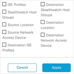
You can use the Filter option to view a subset of the policy matrix, for a
selected set of source and destination groups. You can create a filter to focus only
on the policies that you are interested. To create the filter, select the source and
destination groups that you want to include.
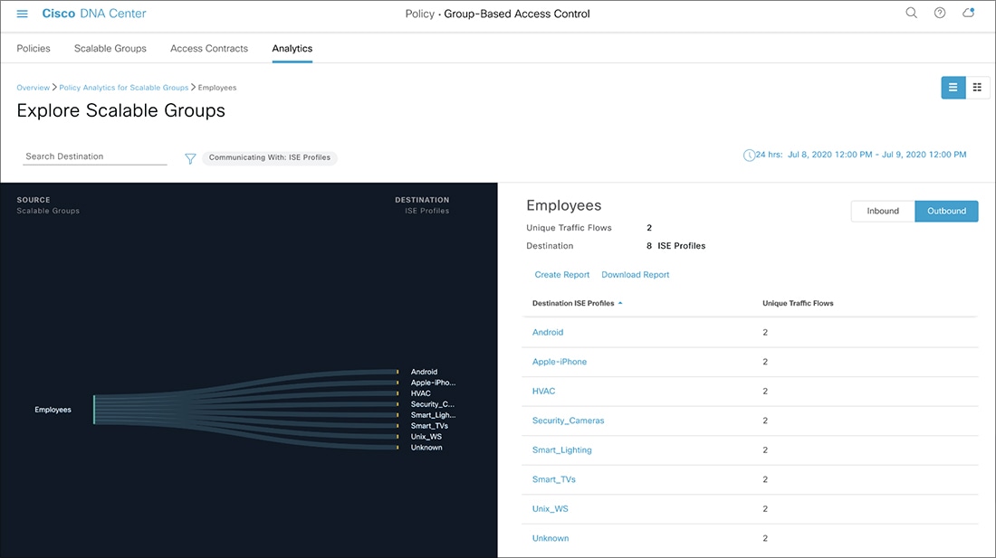
Cisco DNA Center integrates with Cisco ISE. Cisco ISE provides the runtime policy platform for providing policy download to the network devices on behalf of Cisco DNA Center. The TrustSec Workcenter user interface screens for Security Groups, Security Group Access Control Lists (SGACLs), and Egress
Policy are displayed in Read-Only mode in Cisco ISE to prevent policy synchronization issues.
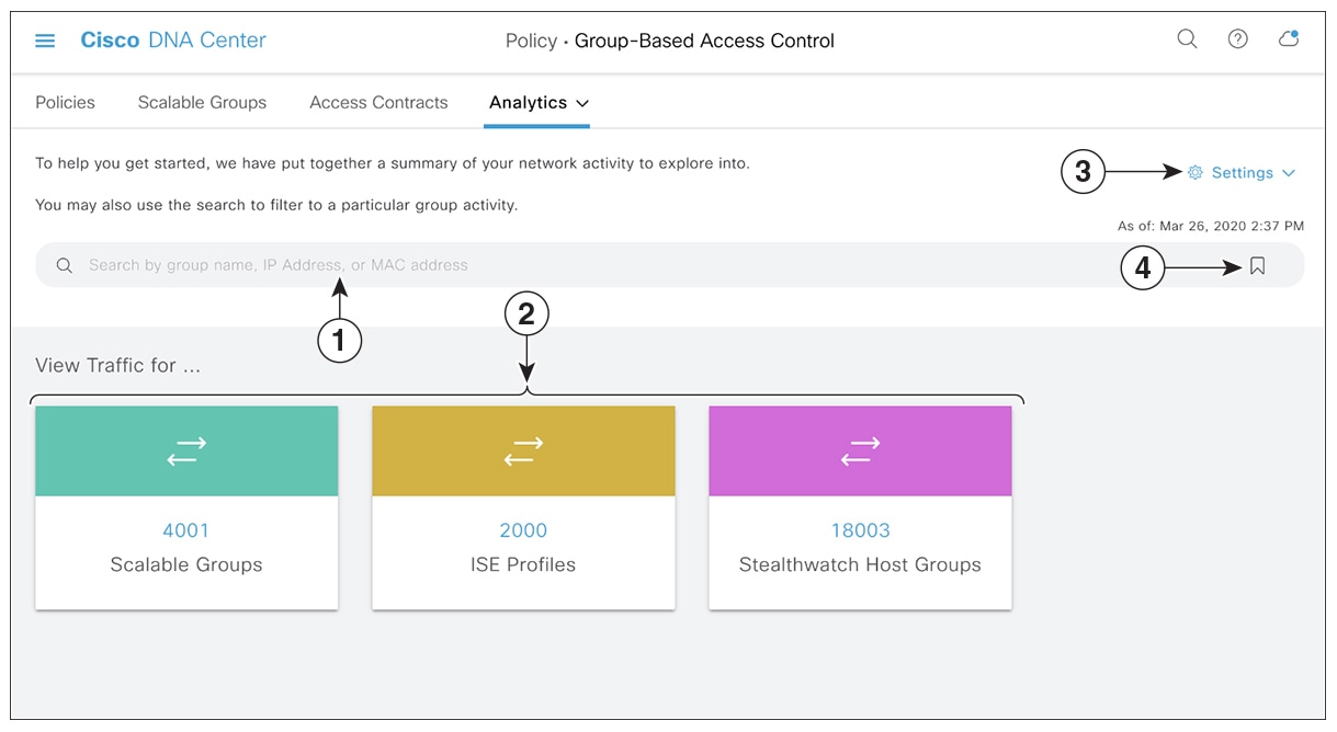
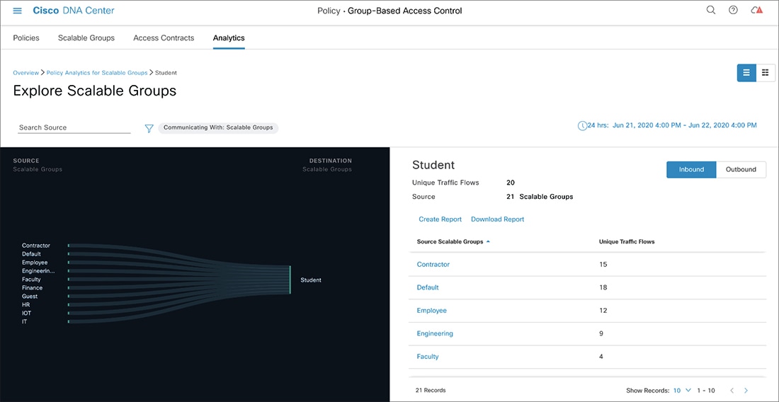
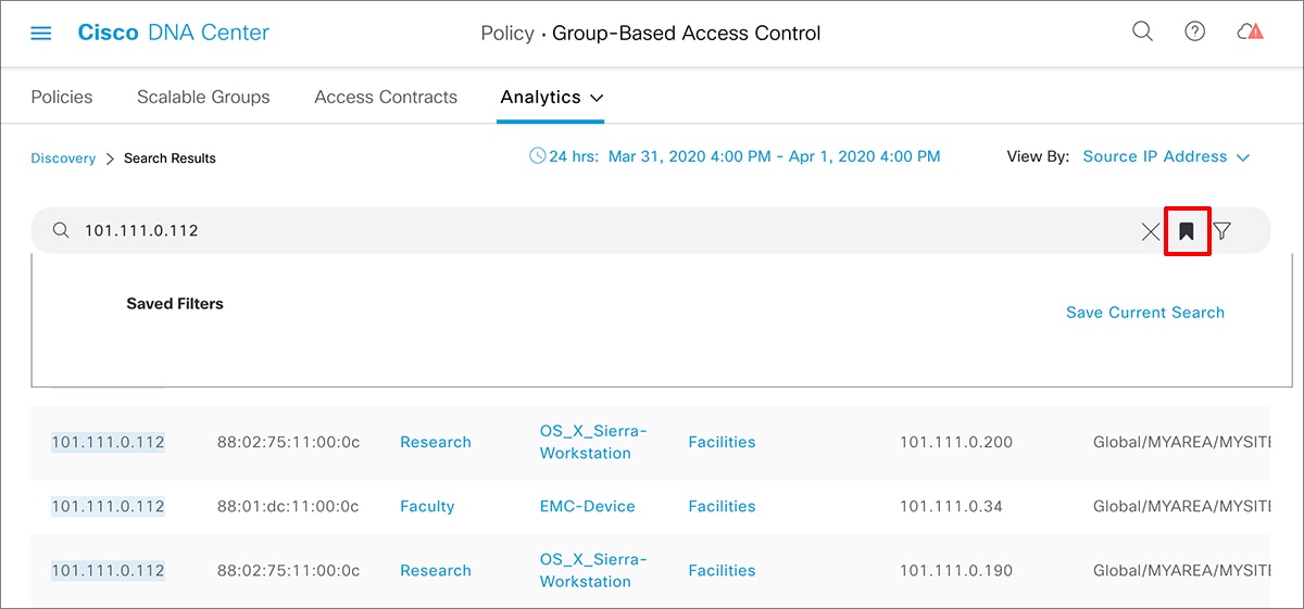
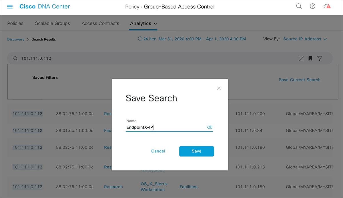
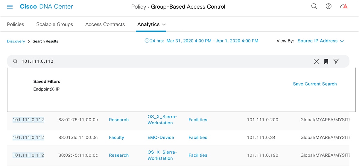
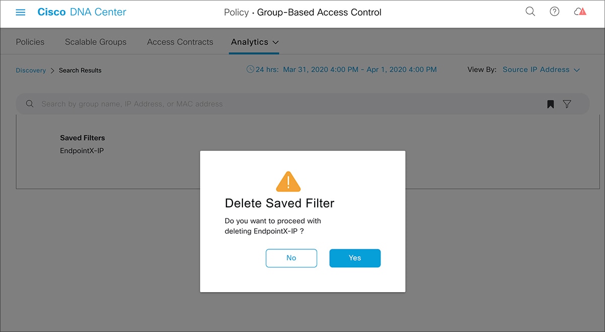
 icon to load a saved filter or save the current search.

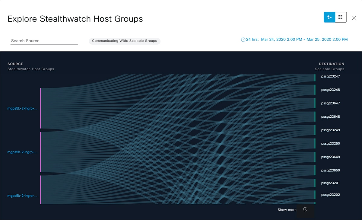
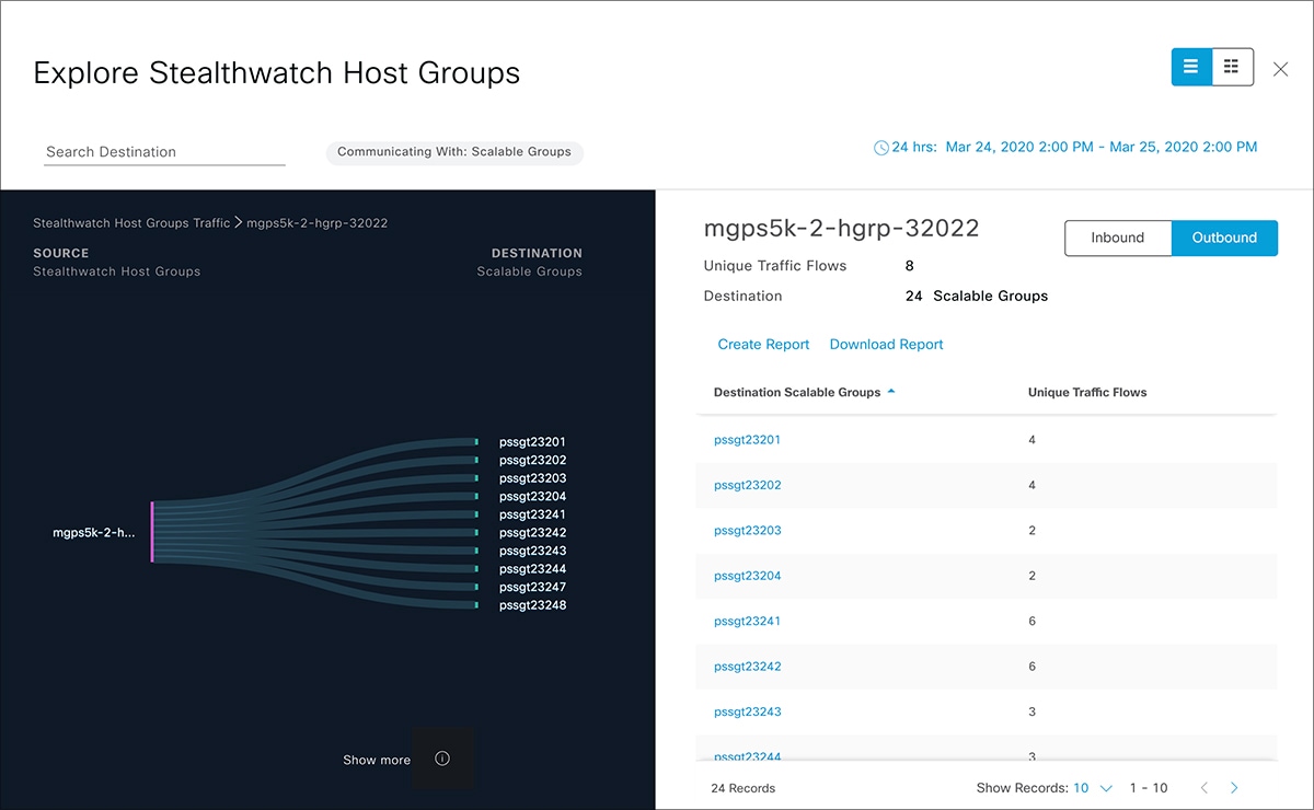
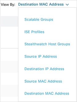
 icon to choose the destination category other than Scalable Groups.
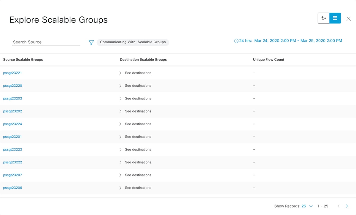
 icon to display the chart view, or
  to display the table view.

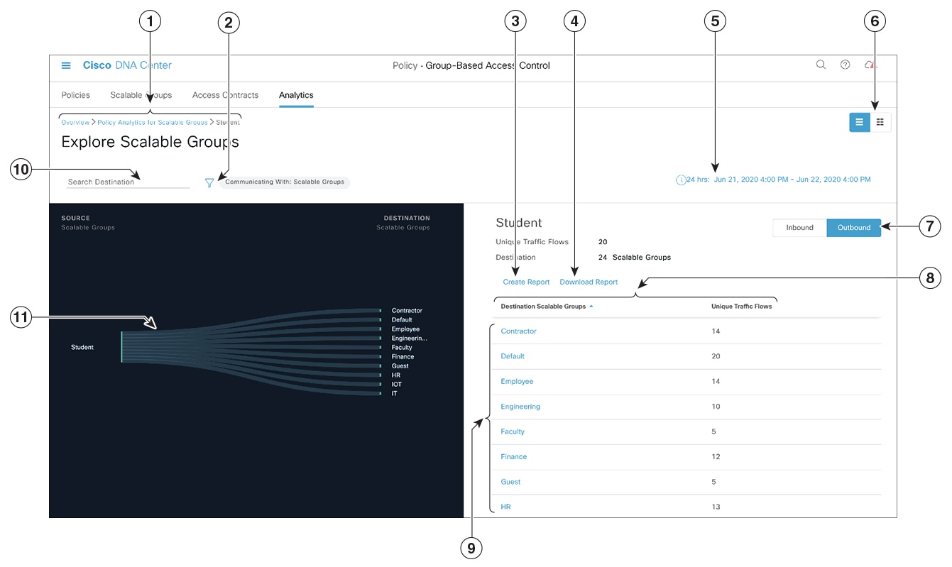


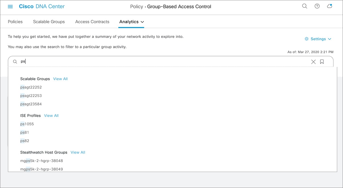
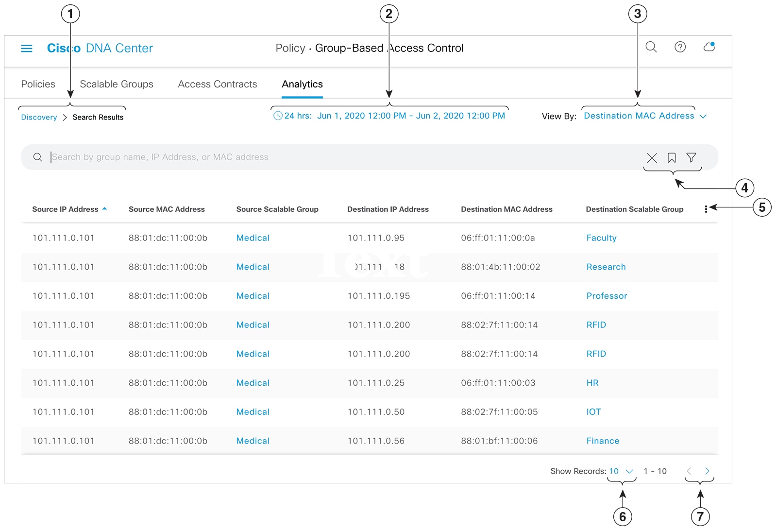
 icon to close the search results.
 ) is used in advanced filtering, and is available only when you search for a MAC address or an IP address. When you click
the
) is used in advanced filtering, and is available only when you search for a MAC address or an IP address. When you click
the 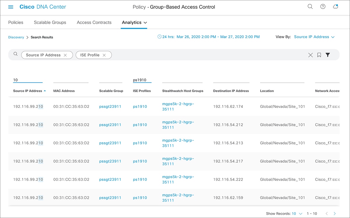
 next to the site you are interested in.
 Feedback