Limitations and Restrictions
Assurance is not supported over NATed connections to managed devices.
The documentation set for this product strives to use bias-free language. For the purposes of this documentation set, bias-free is defined as language that does not imply discrimination based on age, disability, gender, racial identity, ethnic identity, sexual orientation, socioeconomic status, and intersectionality. Exceptions may be present in the documentation due to language that is hardcoded in the user interfaces of the product software, language used based on RFP documentation, or language that is used by a referenced third-party product. Learn more about how Cisco is using Inclusive Language.
Before you begin using the Assurance application, you must configure Assurance. This chapter provides the basic tasks you must do to set up Assurance. Use this chapter in conjunction with the Cisco Digital Network Architecture Center User Guide.
Assurance is not supported over NATed connections to managed devices.
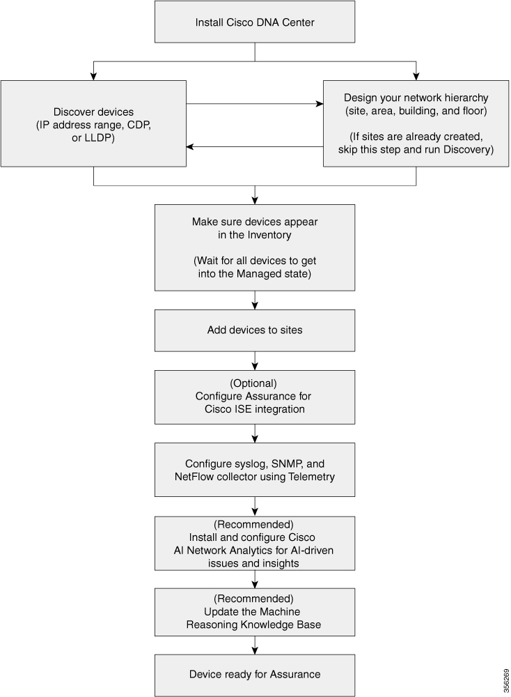
Before you begin using the Assurance application, you must set up Cisco DNA Center to use Assurance.
See the following illustration and the procedure that follows to understand the basic workflow.
| Step 1 |
Install Cisco DNA Center. See the Cisco DNA Center Installation Guide. |
||||
| Step 2 |
Do the following in any order:
|
||||
| Step 3 |
Make sure that the devices appear in the device Inventory. See Display Information About Your Inventory.
|
||||
| Step 4 |
Add devices to sites. |
||||
| Step 5 |
If you are adding APs, we recommend that you assign and position them on a floor map. |
||||
| Step 6 |
If your network uses Cisco Identity Services Engine for user authentication, you can configure Assurance for Cisco ISE integration. This enables you to see more information about wired clients, such as the username and operating system, in Assurance. |
||||
| Step 7 |
Configure the syslog, SNMP traps, and NetFlow Collector servers using Telemetry. |
||||
| Step 8 |
(Recommended) To view AI-driven issues and gain network insights, configure Cisco AI Network Analytics data collection. |
||||
| Step 9 |
(Recommended) To have access to the latest Machine Reasoning workflows, update the Machine Reasoning Knowledge Base. |
||||
| Step 10 |
Start using the Assurance application. |
The Discovery feature scans the devices in your network and sends the list of discovered devices to Inventory.
The Discovery feature scans the devices in your network and sends the list of discovered devices to Inventory.
The Discovery feature also can work with the Device Controllability feature to configure the required network settings on devices, if these settings are not already present on the device.
There are three ways for you to discover devices:
Use Cisco Discovery Protocol (CDP) and provide a seed IP address.
Specify a range of IP addresses. (A maximum range of 4096 devices is supported.)
Use Link Layer Discovery Protocol (LLDP) and provide a seed IP address.
When configuring the Discovery criteria, remember that there are settings that you can use to help reduce the amount of time it takes to discover your network:
CDP Level and LLDP Level: If you use CDP or LLDP as the Discovery method, you can set the CDP or LLDP level to indicate the number of hops from the seed device that you want to scan. The default, level 16, might take a long time on a large network. So, if fewer devices have to be discovered, you can set the level to a lower value.
Subnet Filters: If you use an IP address range, you can specify devices in specific IP subnets for Discovery to ignore.
Preferred Management IP: Whether you use CDP, LLDP, or an IP address range, you can specify whether you want Cisco DNA Center to add any of the device's IP addresses or only the device's loopback address.
 Note |
For Cisco SD-Access Fabric and Cisco DNA Assurance, we recommend that you specify the device's loopback address. |
Regardless of the method you use, you must be able to reach the device from Cisco DNA Center and configure specific credentials and protocols in Cisco DNA Center to discover your devices. These credentials can be configured and saved in the window or on a per-job basis in the Discovery window.
Note |
If a device uses a first hop resolution protocol like Hot Standby Router Protocol (HSRP) or Virtual Router Redundancy Protocol (VRRP), the device might be discovered and added to the inventory with its floating IP address. Later, if HSRP or VRRP fails, the IP address might be reassigned to a different device. This situation can cause issues with the data that Cisco DNA Center retrieves for analysis. |
Before you run Discovery, complete the following minimum prerequisites:
Understand what devices will be discovered by Cisco DNA Center by viewing the Supported Devices List.
Understand that the preferred network latency between Cisco DNA Center and devices is 100 ms. (The maximum latency is 200 ms.)
Ensure at least one SNMP credential is configured on your devices for use by Cisco DNA Center. At a minimum, this can be an SNMPv2C read credential.
Configure SSH credentials on the devices you want Cisco DNA Center to discover and manage. Cisco DNA Center discovers and adds a device to its inventory if at least one of the following criteria is met:
The account that is being used by Cisco DNA Center to SSH into your devices has privileged EXEC mode (level 15).
You configure the device’s enable password as part of the CLI credentials configured in the Discovery job. For more information, see Discovery Configuration Guidelines and Limitations.
When Cisco DNA Center discovers a device, it uses one of the device's IP addresses as the preferred management IP address. The IP address can be that of a built-in management interface of the device, another physical interface, or a logical interface such as Loopback0. You can configure Cisco DNA Center to use the device's loopback IP address as the preferred management IP address, provided the IP address is reachable from Cisco DNA Center.
When you choose Use Loopback IP as the preferred management IP address, Cisco DNA Center determines the preferred management IP address as follows:
If the device has one loopback interface, Cisco DNA Center uses that loopback interface IP address.
If the device has multiple loopback interfaces, Cisco DNA Center uses the loopback interface with the highest IP address.
If there are no loopback interfaces, Cisco DNA Center uses the Ethernet interface with the highest IP address. (Subinterface IP addresses are not considered.)
If there are no Ethernet interfaces, Cisco DNA Center uses the serial interface with the highest IP address.
After a device is discovered, you can update the management IP address from the Inventory window.
The following are the guidelines and limitations for Cisco DNA Center to discover your Cisco Catalyst 3000 Series Switches and Catalyst 6000 Series Switches:
Configure the CLI username and password with privileged EXEC mode (level 15). This is the same CLI username and password that you configure in Cisco DNA Center for the Discovery function. Cisco DNA Center requires the highest access level to the device.
Explicitly specify the transport protocols allowed on individual interfaces for both incoming and outgoing connections. Use the transport input and transport output commands for this configuration. For information about these commands, see the command reference document for the specific device type.
Do not change the default login method for a device's console port and the VTY lines. If a device is already configured with a AAA (TACACS) login, make sure that the CLI credential defined in the Cisco DNA Center is the same as the TACACS credential defined in the TACACS server.
Cisco Wireless Controllers must be discovered using the Management IP address instead of the Service Port IP address. If not, the related wireless controller 360 and AP 360 pages will not display any data.
You can discover devices using Cisco Discovery Protocol (CDP), an IP address range, or LLDP. This procedure shows you how to discover devices and hosts using CDP. For more information about the other discovery methods, see Discover Your Network Using an IP Address Range and Discover Your Network Using LLDP.
Note |
|
Enable CDP on your network devices.
Configure your network devices, as described in Discovery Prerequisites.
Configure your network device's host IP address as the client IP address. (A host is an end-user device, such as a laptop computer or mobile device.)
| Step 1 |
In the Cisco DNA Center GUI, click the Menu icon ( |
| Step 2 |
Click Add Discovery. |
| Step 3 |
In the Discovery Name field, enter a name. |
| Step 4 |
Expand the IP Address/Range area if it is not already visible, and configure the following fields: |
| Step 5 |
Expand the Credentials area and configure the credentials that you want to use for the Discovery job. Choose any of the global credentials that have already been created or configure your own Discovery credentials. If you configure your own credentials, you can save them only for the current job by clicking Save or you can save them for the current and future jobs by checking the Save as global settings check box and then clicking Save. |
| Step 6 |
To configure the protocols to be used to connect with devices, expand the Advanced area and do the following tasks: |
| Step 7 |
Click Discover and select whether to run the discovery now or schedule the discovery for a later time.
Click the notifications icon to view the scheduled discovery tasks. Click Edit to edit the discovery task before the discovery starts. Click Cancel to cancel the scheduled discovery job before it starts. The Discoveries window displays the results of your scan. The Discovery Details pane shows the status (active or inactive) and the Discovery configuration. The Discovery Devices pane displays the host names, IP addresses, and status of the discovered devices. |
You can discover devices using an IP address range, CDP, or LLDP. This procedure shows you how to discover devices and hosts using an IP address range. For more information about the other Discovery methods, see Discover Your Network Using CDP and Discover Your Network Using LLDP.
Your devices must have the required device configurations, as described in Discovery Prerequisites.
| Step 1 |
In the Cisco DNA Center GUI, click the Menu icon ( |
| Step 2 |
Click Add Discovery. |
| Step 3 |
In the Discovery Name field, enter a name. |
| Step 4 |
Expand the IP Address/Ranges area, if it is not already visible, and configure the following fields: |
| Step 5 |
Expand the Credentials area and configure the credentials that you want to use for the Discovery job. Choose any of the global credentials that have already been created or configure your own Discovery credentials. If you configure your own credentials, you can save them for only the current job by clicking Save, or you can save them for the current and future jobs by checking the Save as global settings check box and then clicking Save. |
| Step 6 |
(Optional) To configure the protocols that are to be used to connect with devices, expand the Advanced area and do the following tasks: |
| Step 7 |
Click Discover and select whether to run the discovery now or schedule the discovery for a later time.
Click the notifications icon to view the scheduled discovery tasks. Click Edit to edit the discovery task before the discovery starts. Click Cancel if you want to cancel the scheduled discovery job before it starts. The Discoveries window displays the results of your scan. The Discovery Details pane shows the status (active or inactive) and the Discovery configuration. The Discovery Devices pane displays the host names, IP addresses, and status of the discovered devices. |
You can discover devices using Link Layer Discovery Protocol (LLDP), CDP, or an IP address range. This procedure shows you how to discover devices and hosts using LLDP. For more information about the other discovery methods, see Discover Your Network Using CDP and Discover Your Network Using an IP Address Range.
Note |
|
Enable LLDP on your network devices.
Configure your network devices, as described in Discovery Prerequisites.
Configure your network device's host IP address as the client IP address. (A host is an end-user device, such as a laptop computer or mobile device.)
| Step 1 |
In the Cisco DNA Center GUI, click the Menu icon ( |
| Step 2 |
Click Add Discovery. |
| Step 3 |
In the Discovery Name field, enter a name. |
| Step 4 |
Expand the IP Address/Range area and configure the following fields: |
| Step 5 |
Expand the Credentials area and configure the credentials that you want to use for the Discovery job. Choose any of the global credentials that have already been created, or configure your own Discovery credentials. If you configure the credentials, you can choose to save them for future jobs by checking the Save as global settings check box. |
| Step 6 |
(Optional) To configure the protocols to be used to connect with devices, expand the Advanced area and do the following tasks:
|
| Step 7 |
Click Discover and select whether to run the discovery now or schedule the discovery for a later time.
Click the notifications icon to view the scheduled discovery tasks. Click Edit to edit the discovery task before the discovery starts. Click Cancel if you want to cancel the scheduled discovery job before it starts. The Discoveries window displays the results of your scan. The Discovery Details pane shows the status (active or inactive) and the Discovery configuration. The Discovery Devices pane displays the host names, IP addresses, and status of the discovered devices. |
Manage Discovery Jobs
| Step 1 |
In the Cisco DNA Center GUI, click the Menu icon ( |
| Step 2 |
Click View All Discoveries. |
| Step 3 |
To stop an active Discovery job, perform these steps:
|
| Step 4 |
To restart an inactive Discovery job, perform these steps:
|
You can clone a Discovery job and retain all of the information defined for that job.
You should have run at least one Discovery job.
| Step 1 |
In the Cisco DNA Center GUI, click the Menu icon ( |
| Step 2 |
Click View All Discoveries. |
| Step 3 |
From the Discoveries pane, select the Discovery job. |
| Step 4 |
Click Copy & Edit. Cisco DNA Center creates a copy of the Discovery job, named Copy of Discovery_Job . |
| Step 5 |
(Optional) Change the name of the Discovery job. |
| Step 6 |
Define or update the parameters for the new Discovery job. |
| Step 1 |
In the Cisco DNA Center GUI, click the Menu icon ( |
| Step 2 |
Click View All Discoveries. |
| Step 3 |
From the Discoveries pane, select the Discovery job that you want to delete. |
| Step 4 |
Click Delete. |
| Step 5 |
Click OK to confirm. |
You can view information about a Discovery job, such as the settings and credentials that were used. You also can view the historical information about each Discovery job that was run, including information about the specific devices that were discovered or that failed to be discovered.
Run at least one Discovery job.
| Step 1 |
In the Cisco DNA Center GUI, click the Menu icon ( |
| Step 2 |
Click View All Discoveries. |
| Step 3 |
From the Discoveries pane, select the Discovery job. Alternatively, use the Search function to find a Discovery job by device IP address or name. |
| Step 4 |
Click the down arrow next to one of the following areas for more information:
|
You can create a network hierarchy that represents your network's geographical locations. Your network hierarchy can contain sites, which contains buildings and areas.
The Design area is where you create the structure and framework of your network, including the physical topology, network settings, and device type profiles that you can apply to devices throughout your network. Use the Design workflow if you do not already have an existing infrastructure. If you have an existing infrastructure, use the Discovery feature. For more information, see About Discovery.
You can perform these tasks in the Design area:| Step 1 |
Create your network hierarchy. |
| Step 2 |
Define global network settings. |
| Step 3 |
Define network profiles. |
You can create a network hierarchy that represents your network's geographical locations. Your network hierarchy can contain sites, which in turn contain buildings and areas. You can create site and building IDs to easily identify where to apply design settings or configurations later. By default, there is one site called Global.
The network hierarchy has a predetermined hierarchy:
Areas or Sites do not have a physical address, such as the United States. You can think of areas as the largest element. Areas can contain buildings and subareas. For example, an area called United States can contain a subarea called California, and the subarea California can contain a subarea called San Jose.
Buildings have a physical address and contain floors and floor plans. When you create a building, you must specify a physical address and latitude and longitude coordinates. Buildings cannot contain areas. By creating buildings, you can apply settings to a specific area.
Floors are within buildings and consist of cubicles, walled offices, wiring closets, and so on. You can add floors only to buildings.
The following is a list of tasks that you can perform:
Create a new network hierarchy. For more information, see Create a Site in a Network Hierarchy.
Upload an existing network hierarchy from Cisco Prime Infrastructure. For more information, see Upload an Existing Site Hierarchy.
Use a graphical application that can save the map image files to any of these formats: .jpg, .gif, .png, .dxf, and .dwg.
Ensure that the dimension of an image is larger than the combined dimension of all the buildings and outside areas that you plan to add to the campus map.
Map image files can be of any size. Cisco DNA Center imports the original image to its database at a full definition, but during display, it automatically resizes them to fit the workspace.
Obtain the horizontal and vertical dimensions of the site in feet or meters before importing. This helps you to specify these dimensions during map import.
Cisco DNA Center allows you to easily define physical sites and then specify common resources for those sites. The Design area uses a hierarchical format for intuitive use, while eliminating the need to redefine the same resource in multiple places when provisioning devices. By default, there is one site called Global. You can add more sites, buildings, and areas to your network hierarchy. You must create at least one site before you can use the provision features.
| Step 1 |
In the Cisco DNA Center GUI, click the Menu icon ( A world map is displayed in the right pane. |
| Step 2 |
In the Network Hierarchy window, click or click the gear icon |
| Step 3 |
Enter a name for the site in the Area Name field. |
| Step 4 |
From the Parent drop-down list, choose a parent node. By default, Global is the parent node. |
| Step 5 |
Click Add. The site is created under the parent node in the left pane. You can also upload an existing hierarchy. For more information, see Upload an Existing Site Hierarchy. |
| Step 1 |
In the Cisco DNA Center GUI, click the Menu icon ( A world map is displayed in the right pane. |
| Step 2 |
In the Network Hierarchy window, click , or click the gear icon You can also upload an existing hierarchy. |
| Step 3 |
In the Building Name field, enter a name for the building. |
| Step 4 |
From the Parent drop-down list, choose a parent node. By default, Global is the parent node. |
| Step 5 |
In the Address field, enter an address. If you are connected to the Internet, as you enter the address, the Design Application narrows down the known addresses to the one you enter. The user can move the marker to change the position on the map. When you see that the correct address appears in the window, select it. When you select a known address, the Longitude and Latitude coordinates fields are automatically populated. |
| Step 6 |
Click Add. The building that you created is added under the parent site in the left menu. |
| Step 7 |
To add another area or building, in the hierarchy frame, click the gear icon |
After you add a building, create floors and upload a floor map.
| Step 1 |
In the Cisco DNA Center GUI, click the Menu icon ( |
| Step 2 |
Expand the Global site and the previously created area to see all the previously created buildings. |
| Step 3 |
Click the gear icon |
| Step 4 |
Enter a name for the floor. The floor name has a 21-character limit. The floor name must start with a letter or a hyphen (-) and the string following the first character can include one or more of the following:
|
| Step 5 |
Define the type of floor by choosing the Radio Frequency (RF) model from the Type (RF Model) drop-down list: Indoor High Ceiling, Outdoor Open Space, Drywall Office Only, and Cubes And Walled Offices. This defines if the floor is an open space or a drywall office, and so on. Based on the RF model selected, the wireless signal strength and the distribution of heatmap is calculated. |
| Step 6 |
You can drag a floor plan on to the map or upload a file. Cisco DNA Center supports the following file types: .jpg, .gif, .png, .dxf, and .dwg. After you import a map, make sure that you mark the Overlay Visibility as On (). By default, overlays are not displayed after you import a map. 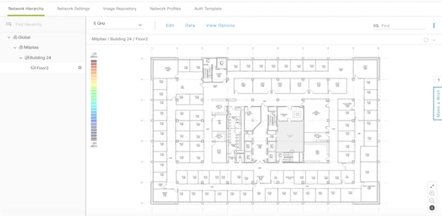 |
| Step 7 |
Click Add. |
Manage Network Hierarchy
You can upload a CSV file or a map archive file that contains an existing network hierarchy. For example, you can upload a CSV file with location information that you exported from Cisco Prime Infrastructure. For more information, see Export Maps Archive on how to export maps from Cisco Prime Infrastructure.
Note |
Before importing a map archive file into Cisco DNA Center, make sure that the devices such as Cisco Wireless Controllers and its associated APs are discovered and listed on the Cisco DNA Center inventory page. |
| Step 1 |
In the Cisco DNA Center GUI, click the Menu icon ( A world map is displayed in the right pane. |
| Step 2 |
Drag and drop your CSV file, or navigate to where your CSV file is located, then click Import to import the Cisco Prime Infrastructure Groups CSV file. If you do not have an existing CSV file, click Download Template to download a CSV file that you can edit and upload. |
| Step 3 |
To import the Cisco Prime Infrastructure maps tar.gz archive file, click Import > Map Import. |
| Step 4 |
Drag and drop the map archive file into the boxed area in the Import Site Hierarchy Archive dialog box, or click the click to select link and browse to the archive file. |
| Step 5 |
Click Save to upload the file. The Import Preview window appears, which shows the imported file. |
| Step 1 |
From the Cisco Prime Infrastructure user interface, choose . |
| Step 2 |
From the Export drop-down list, choose Map Archive. |
| Step 3 |
On the Select Sites window, configure the following. You can either select map information or calibration information to be included in the maps archive.
|
| Step 4 |
Click Generate Map Archive. A message Exporting data is in progress is displayed. |
| Step 5 |
Click Done. |
You can search the network hierarchy to quickly find a site, building, or area. This is particularly helpful after you have added many sites, areas, or buildings.
|
To search the tree hierarchy, in the Find Hierarchy search field in the left pane and enter either the partial or full name of the site, building, or floor name that you are searching. The tree hierarchy is filtered based on the text you enter in the search field. |
| Step 1 |
In the Cisco DNA Center GUI, click the Menu icon ( |
| Step 2 |
In the left pane, navigate to the corresponding site that you want to edit. |
| Step 3 |
Click the gear icon |
| Step 4 |
Make the necessary changes, and click Update. |
| Step 1 |
In the Cisco DNA Center GUI, click the Menu icon ( |
| Step 2 |
In the left pane, navigate to the site that you want to delete. |
| Step 3 |
Click the gear icon |
| Step 4 |
Confirm the deletion. |
| Step 1 |
In the Cisco DNA Center GUI, click the Menu icon ( |
| Step 2 |
In the left tree pane, navigate to the building that you want to edit. |
| Step 3 |
Click the gear icon |
| Step 4 |
Make the necessary changes in the Edit Building window, and click Update. |
| Step 1 |
In the Cisco DNA Center GUI, click the Menu icon ( |
||
| Step 2 |
In the left pane, navigate to the building that you want to delete. |
||
| Step 3 |
Click the gear icon next to the building and select Delete Building. |
||
| Step 4 |
Confirm the deletion.
|
After you add a floor, you can edit the floor map so that it contains obstacles, areas, and APs on the floor.
| Step 1 |
In the Cisco DNA Center GUI, click the Menu icon ( |
| Step 2 |
Expand the network hierarchy to find the floor that you want to edit, or enter the floor name in the Search Hierarchy text field in the left pane. |
| Step 3 |
Make the necessary changes in the Edit Floor dialog window, and click Update. |
The floor view navigation pane provides access to multiple map functions like:
Use the Find feature located at the top-right corner of the floor map window to find specific floor elements such as APs, sensors, clients, and so on. The elements that match the search criteria are displayed on the floor map along with a table in the right pane. When you hover your mouse over the table, it points to the search element on the floor map with a connecting line.
Click the ![]() icon at the top-right corner of the floor map window to:
icon at the top-right corner of the floor map window to:
Export a floor plan as a PDF.
Measure the distance on the floor map.
Set the scale to modify the floor dimensions.
Click the ![]() icon at the bottom-right of the floor map window to zoom in on a location. The zooming levels depend upon the resolution
of an image. A high-resolution image might provide more zoom levels. Each zoom level comprises of a different style map shown
at different scales, each one showing the corresponding details. Some maps are of the same style, but at a smaller or larger
scale.
icon at the bottom-right of the floor map window to zoom in on a location. The zooming levels depend upon the resolution
of an image. A high-resolution image might provide more zoom levels. Each zoom level comprises of a different style map shown
at different scales, each one showing the corresponding details. Some maps are of the same style, but at a smaller or larger
scale.
Click the ![]() icon to see a map with fewer details.
icon to see a map with fewer details.
Click the ![]() icon to view the map icon legend.
icon to view the map icon legend.
Using the Edit option available on the floor area, you can:
Add, position, and delete the following floor elements:
Access Points
Sensors
Add, edit, and delete the following overlay objects:
Coverage Areas
Obstacles
Location Regions
Rails
Markers
GPS Markers
Follow these guidelines while placing APs on the floor map:
Place APs along the periphery of coverage areas to keep devices close to the exterior of rooms and buildings. APs placed in the center of these coverage areas provide good data on devices that would otherwise appear equidistant from all other APs.
Location accuracy can be improved by increasing overall AP density and moving APs close to the perimeter of the coverage area.
In long and narrow coverage areas, avoid placing APs in a straight line. Stagger them so that each AP is more likely to provide a unique snapshot of the device location.
Although the design provides enough AP density for high-bandwidth applications, location suffers because each AP view of a single device is not varied enough. Therefore, location is difficult to determine. Move the APs to the perimeter of the coverage area and stagger them. Each has a greater likelihood of offering a distinctly different view of the device, resulting in higher location accuracy.
For optimal heatmap visibility on floor maps, configure the AP height to approximately 10 feet (3 meters) or lower.
Cisco DNA Center computes heatmaps for the entire map that show the relative intensity of the Radio Frequency (RF) signals in the coverage area. The heatmap is only an approximation of the actual RF signal intensity because it does not consider the attenuation of various building materials, such as drywall or metal objects, nor does it display the effects of RF signals bouncing off obstructions.
Make sure that you have Cisco APs in your inventory. If not, discover APs using the Discovery feature. See About Discovery.
Cisco DNA Center supports the following 802.11ax APs:
Cisco Catalyst 9120 Access Points
Cisco Catalyst 9117 Access Points
Cisco Catalyst 9115 Access Points
Cisco Catalyst 9100 Access Points
| Step 1 |
In the Cisco DNA Center GUI, click the Menu icon ( |
||
| Step 2 |
In the left pane, select the floor. |
||
| Step 3 |
Click Edit, which is located above the floor plan in the middle pane. |
||
| Step 4 |
In the Floor Elements panel, next to Access Points, click Add. Access points that are not assigned to any floors appear in the list. |
||
| Step 5 |
On the Add APs window, check the check boxes of the access points to select the APs in bulk, and click Add Selected. Alternatively click Add next to an access point.
|
||
| Step 6 |
Close the Add APs window after assigning APs to the floor area. |
||
| Step 7 |
Newly added APs appear on the top-right corner of the floor map. |
||
| Step 8 |
In the Floor Elements pane, next to Access Points, click Position to position the APs correctly on the map.
|
||
| Step 9 |
After you have completed placing and adjusting access points, click Save. The heatmap is generated based on the new position of the AP. If a Cisco Connected Mobile Experiences (CMX) is synchronized with Cisco DNA Center, you can view the location of clients on the heatmap. See Create Cisco CMX Settings. |
||
| Step 10 |
In the Floor Elements panel, next to Access Points, click Delete. |
||
| Step 11 |
Check the check boxes next to the access points that you want to delete, and click Delete Selected.
|
Hover your cursor over the AP icon on the floor map to view AP details, Rx neighbor information, client information, and Device 360 information.
Click Info to view the following AP details:
Associated: Indicates whether an AP is associated or not.
Name: AP name.
MAC Address: MAC address of the AP.
Model: AP model number.
Admin/Mode: Administration status of the AP mode.
Type: Radio type.
OP/Admin: Operational status and AP mode.
Channel: Channel number of the AP.
Antenna: Antenna name.
Azimuth: Direction of the antenna.
Click the Rx Neighbors radio button to view the immediate Rx neighbors for the selected AP on the map with a connecting line. The floor map also shows whether the AP is associated or not along with the AP name.
Click Device 360 to get a 360° view of a specific network element (router, switch, AP, or Cisco wireless controller). See the Monitor and Troubleshoot the Health of a Device topic in the Cisco DNA Assurance User Guide.
Note |
For Device 360 to open, you must have the Assurance application installed. |
Note |
Make sure you have the Cisco AP 1800S sensor in your inventory. The Cisco Aironet 1800s Active Sensor must be provisioned using Plug and Play for it to show up in the Inventory. See the Provision the Wireless Cisco Aironet 1800s Active Sensor topic in the Cisco DNA Assurance User Guide. |
A sensor device is a dedicated AP 1800s sensor. The Cisco Aironet 1800s Active Sensor gets bootstrapped using PnP. After it obtains the Assurance server reachability details, it directly communicates with the Assurance server.
| Step 1 |
In the Cisco DNA Center GUI, click the Menu icon ( |
||
| Step 2 |
In the left pane, select the floor. |
||
| Step 3 |
Click Edit, which is located above the floor plan. |
||
| Step 4 |
In the Floor Elements panel, next to Sensors, click Add. |
||
| Step 5 |
On the Add Sensors window, check the check boxes of the sensors that you want to add. Alternatively, click Add next to the sensor row to add sensors.
|
||
| Step 6 |
Close the Add Sensors window after assigning sensors to the floor map. |
||
| Step 7 |
To position the sensors correctly, in the Floor Elements pane, next to Sensors, click Position to place them correctly on the map. |
||
| Step 8 |
After you have completed placing and adjusting sensors, click Save. |
||
| Step 9 |
To delete a sensor, in the Floor Elements pane, next to Sensors, click Delete. |
||
| Step 10 |
Check the check boxes of the sensors that you want to delete, and click Delete Selected.
|
By default, any floor area or outside area defined as part of a building map is considered as a wireless coverage area.
If you have a building that is nonrectangular or you want to mark a nonrectangular area within a floor, you can use the map editor to draw a coverage area or a polygon-shaped area.
| Step 1 |
In the Cisco DNA Center GUI, click the Menu icon ( |
||
| Step 2 |
In the left pane, select the floor. |
||
| Step 3 |
Click Edit, which is located above the floor plan in the middle pane. |
||
| Step 4 |
In the Overlays panel, next to Coverage Areas, click Add. |
||
| Step 5 |
To draw a coverage area, from the Type drop-down list, choose Coverage Area.
|
||
| Step 6 |
To draw a polygon-shaped area, from the Type drop-down list, choose Perimeter.
|
||
| Step 7 |
To edit a coverage area, in the Overlays panel, next to Coverage Areas, click Edit. The available coverage areas are highlighted on the map. |
||
| Step 8 |
Make the changes and click Save after the changes. |
||
| Step 9 |
To delete a coverage area, in the Overlays panel, next to Coverage Areas, click Delete. The available coverage areas are highlighted on the map. |
||
| Step 10 |
Hover your cursor over the coverage area and, click delete. |
||
| Step 11 |
Click Save after the deletion. |
You can create obstacles so that they can be considered while computing Radio Frequency (RF) prediction heatmaps for access points.
| Step 1 |
In the Cisco DNA Center GUI, click the Menu icon ( |
| Step 2 |
In the left pane, select the floor. |
| Step 3 |
Click Edit, which is located above the floor plan in the middle pane. |
| Step 4 |
In the Overlays panel, next to Obstacles, click Add. |
| Step 5 |
In the Obstacle Creation dialog box, choose an obstacle type from the Obstacle Type drop-down list. The type of obstacles that you can create are Thick Wall, Light Wall, Heavy Door, Light Door, Cubicle, and Glass. |
| Step 6 |
Click Add Obstacle. |
| Step 7 |
Move the drawing tool to the area where you want to create an obstacle. |
| Step 8 |
Click the drawing tool to start and stop a line. |
| Step 9 |
After you have outlined the area, double-click the area to highlight it. |
| Step 10 |
In the Obstacle Creation window, click Done. |
| Step 11 |
Click Save to save the obstacle on the floor map. |
| Step 12 |
To edit an obstacle, in the Overlays panel, next to Obstacles, click Edit. All the available obstacles are highlighted on the map. |
| Step 13 |
Click Save after the changes. |
| Step 14 |
To delete an obstacle, in the Overlays panel, next to Obstacles, click Delete. All the available obstacles are highlighted on the map. |
| Step 15 |
Hover your cursor over the obstacle and click to delete. |
| Step 16 |
Click Save. |
You can create inclusion and exclusion areas to further refine location calculations on a floor. You can define the areas that are included (inclusion areas) in the calculations and those areas that are not included (exclusion areas). For example, you might want to exclude areas such as an atrium or stairwell within a building, but include a work area, such as cubicles, labs, or manufacturing floors.
Inclusion and exclusion areas can be any polygon-shaped area and must have at least 3 points.
You can only define 1 inclusion region on a floor. By default, an inclusion region is defined for each floor area when it is created. The inclusion region is indicated by a solid aqua line, and generally outlines the entire floor area.
You can define multiple exclusion regions on a floor area.
| Step 1 |
In the Cisco DNA Center GUI, click the Menu icon ( |
| Step 2 |
In the left pane, select the floor. |
| Step 3 |
In the Overlays panel, next to Location Regions, click Add. |
| Step 4 |
In the Location Region Creation dialog window, from the Inclusion Type drop-down list, choose an option. |
| Step 5 |
Click Add Location Region. A drawing icon appears to outline the inclusion area. |
| Step 6 |
To begin defining the inclusion area, move the drawing tool to a starting point on the map and click once. |
| Step 7 |
Move the cursor along the boundary of the area you want to include and click to end a border line. Click again to define the next boundary line. |
| Step 8 |
Repeat Step 7 until the area is outlined and then double-click the drawing icon. A solid aqua line defines the inclusion area. |
| Step 9 |
Click Save. |
To further refine location calculations on a floor, you can define areas that are excluded (exclusion areas) in the calculations. For example, you might want to exclude areas such as an atrium or stairwell within a building. As a rule, exclusion areas are defined within the borders of an inclusion area.
| Step 1 |
In the Cisco DNA Center GUI, click the Menu icon ( |
| Step 2 |
In the left pane, select the floor. |
| Step 3 |
Click Edit, which is located above the floor plan in the middle pane. |
| Step 4 |
In the Overlays panel, next to Location Regions, click Add. |
| Step 5 |
In the Location Region Creation window, from the Exclusion Type drop-down list, choose a value. |
| Step 6 |
Click Location Region. A drawing icon appears to outline the exclusion area. |
| Step 7 |
To begin defining the exclusion area, move the drawing icon to a starting point on the map and click once. |
| Step 8 |
Move the drawing icon along the boundary of the area that you want to exclude. Click once to start a boundary line, and click again to end the boundary line. |
| Step 9 |
Repeat the preceding step until the area is outlined and then double-click the drawing icon. The defined exclusion area is shaded in purple when the area is fully defined. |
| Step 10 |
To define more exclusion regions, repeat Step 5 to Step 9. |
| Step 11 |
When all the exclusion areas are defined, click Save. |
| Step 1 |
In the Overlays panel, next to Location Regions, click Edit. |
| Step 2 |
Make the necessary changes, and click Save. |
| Step 1 |
In the Overlays panel, next to Location Regions, click Delete. |
| Step 2 |
Hover your cursor over the region that you want to delete, and click Delete. |
| Step 3 |
Click Save. |
You can define a rail line on a floor that represents a conveyor belt. Also, you can define an area around the rail area known as the snap-width to further assist location calculations. This represents the area in which you expect clients to appear. Any client located within the snap-width area is plotted on the rail line (majority) or outside of the snap-width area (minority).
The snap-width area is defined in feet or meters (user-defined) and represents the distance that is monitored on either side (east and west or north and south) of the rail.
| Step 1 |
In the Cisco DNA Center GUI, click the Menu icon ( |
| Step 2 |
In the left pane, select the floor. |
| Step 3 |
Click Edit, which is located above the floor plan in the middle pane. |
| Step 4 |
In the Overlays panel, next to Rails, click Add. |
| Step 5 |
Enter a snap-width (feet or meters) for the rail, and click Add Rail. A drawing icon appears. |
| Step 6 |
Click the drawing icon at the starting point of the rail line. Click again when you want to stop drawing the line or change the direction of the line. |
| Step 7 |
Click the drawing icon twice when the rail line is drawn on the floor map. The rail line appears on the map and is bordered on either side by the defined snap-width region. |
| Step 8 |
Click Save. |
| Step 9 |
In the Overlays panel, next to Rails, click Edit. The available rails are highlighted on the map. |
| Step 10 |
Make changes, and click Save. |
| Step 11 |
In the Overlays panel, next to Rails, click Delete. All the available rail lines are highlighted on the map. |
| Step 12 |
Hover your cursor over the rail line that you want to delete, and click Delete. |
| Step 13 |
Click Save. |
| Step 1 |
In the Cisco DNA Center GUI, click the Menu icon ( |
| Step 2 |
In the left pane, select the floor. |
| Step 3 |
Click Edit, which is located above the floor plan in the middle pane. |
| Step 4 |
In the Overlays panel, next to Markers, click Add. A drawing icon appears. |
| Step 5 |
Enter the name for the markers, and then click Add Marker. |
| Step 6 |
Click the drawing icon and place the marker on the map. |
| Step 7 |
Click Save. |
| Step 8 |
In the Overlays panel, next to Markers, click Edit. The available markers are highlighted on the map. |
| Step 9 |
Make changes, and click Save. |
| Step 10 |
In the Overlays panel, next to Markers, click Delete. All the available markers are highlighted on the map. |
| Step 11 |
Hover your cursor on the marker that you want to delete, and click delete. |
| Step 12 |
Click Save. |
Click the View Options, which is located above the floor plan in the middle pane. The floor map along with these panels appear in the right pane: Access Points, Sensor, Overlay Objects, Map Properties, and Global Map Properties.
You can modify the appearance of the floor map by selecting or unselecting various parameters. For example, if you want to view only the access point information on the floor map, check the Access Point check box. You can expand each panel to configure various settings available for each floor element.
Click the On/Off button next to Access Points to view access points on the map. Expand the Access Points panel to configure these settings:
Display Label—From the drop-down list, choose a text label that you want to view on the floor map for the AP. The available display labels are:
None—No labels are displayed for the selected access point.
Name—AP name.
AP MAC Address—AP MAC address.
Controller IP—IP address of Cisco Wireless Controller to which the access point is connected.
Radio MAC Address—Radio MAC address.
IP Address
Channel—Cisco Radio channel number or Unavailable (if the access point is not connected).
Coverage Holes—Percentage of clients whose signal has become weaker until the client lost its connection. It shows Unavailable for access points that are not connected and MonitorOnly for access points that are in monitor-only mode.
TX Power—Current Cisco Radio transmit power level (with 1 being high) or Unavailable (if the access point is not connected). If you change the radio band, the information on the map changes accordingly.
The power levels differ depending on the type of access point. The 1000 series APs accept a value between 1 and 5, the 1230 access points accept a value between 1 and 7, and the 1240 and 1100 series access points accept a value between 1 and 8.
Channel and Tx Power—Channel and transmit power level (or Unavailable if the access point is not connected).
Utilization—Percentage of bandwidth used by the associated client devices (including receiving, transmitting, and channel utilization). Displays Unavailable for disassociated access points and MonitorOnly for access points in monitor-only mode.
Tx Utilization—Transmitted (Tx) utilization for the specified interface.
Rx Utilization—Received (Rx) utilization for the specified interface.
Ch Utilization—Channel utilization for the specified access point.
Assoc. Clients—Total number of clients associated.
Dual-Band Radios—Identifies and marks the XOR dual-band radios on the Cisco Aironet 2800 and 3800 Series Access Points.
Health Score—AP health score.
Issue Count
Coverage Issues
AP Down Issues
Heatmap Type—Heatmap is a graphical representation of Radio Frequency (RF) wireless data where the values taken by variable are represented in maps as colors. The current heatmap is computed based on the RSSI prediction model, antenna orientation, and AP transmit power. From the Heatmap Type drop-down list, select the heatmap type: None, AP RSSI, Client Density, IDS, Planned Heatmap, or Coverage.
None
AP RSSI—Shows the coverage heatmap which identifies the strength of wireless signal in the specific band.
RSSI Cut off (dBm)—Drag the slider to set the RSSI cutoff level. The RSSI cutoff ranges from -60 dBm to -90 dBm.
Heatmap Opacity (%)—Drag the slider between 0 to 100 to set the heatmap opacity.
Heatmap Color Scheme—Shows the green color as good heatmap coverage and red color as poor heatmap coverage.
Client Density—Shows the client density of associated clients.
Map Opacity (%)—Drag the slider to set the map opacity.
IDS—IDS heatmap shows the monitor mode access point coverage provided to the wireless clients on a floor map.
Planned Heatmap—A planned heatmap is a hypothetical heatmap which shows the possible coverage of planned access points on a floor map.
Coverage—If you have monitor mode access points on the floor plan, you can select coverage heatmap. A coverage heatmap excludes monitor mode access points.
The AP details are reflected on the map immediately. Hover your cursor over the AP icon on the map to view AP details, RX neighbors details, client details, and switch information.
Click the Sensors button to view sensors on the map. Expand the Sensors panel to configure these settings:
Display Label: From the drop-down list, choose a text label that you want to view on the floor map for the selected access point. The available display labels are:
None
Name: Sensor name.
Sensor MAC Address: Sensor MAC address.
Expand the Overlay Objects panel to configure these settings. Use the On/Off buttons to view these overlay objects on the map.
Coverage Areas
Location Regions
Obstacles
Rails
Markers
Expand the Map Properties panel to configure:
Auto Refresh—Provides an interval drop-down list to set how often you want to refresh maps data from the database. From the Auto Refresh drop-down list, set the time intervals: None, 1 min, 2 mins, 5 mins, or 15 mins.
Expand the Global Map Properties panel to configure:
Unit of Measure—From the drop-down list, set the dimension measurements for maps to either Feet or Meters.
Click Access Point under the Filters panel in the right pane.
Choose the radio type from the drop-down list, located above the floor map in the middle pane: 2.4 GHz, 5 GHz, or 2.4 GHz & 5 GHz.
Click + Add Rule to add a query:
Choose the access point identifier you want to view on the map.
Choose the parameter by which you want to filter access points.
Enter the specific filter criteria in the text box for the applicable parameters, and click Go. The search results appear in a tabular format.
Click Apply Filters to List to view the filter results on the map. To view a particular access point on the map, check the check box of the access point in the table that is displayed, and click Show Selected on Maps.
When you hover your mouse cursor over the search result in the table, the location of the AP is marked by a line on the map.
Click Sensor under the Filters panel in the right pane.
Choose the radio type from the drop-down list, located above the floor map in the middle pane: 2.4 GHz, 5 GHz, or 2.4 GHz & 5 GHz.
Click + Add Rule to add a query:
Choose the sensor identifier you want to view on the map: Name and MAC Address.
Choose the parameter by which you want to filter sensors.
Enter the specific filter criteria in the text box for the applicable parameters, and click Go. The search results appear in a tabular format.
Click Apply Filters to List to view the filter results on the map. To view a particular sensor on the map, check the check box of the sensor in the table that is displayed, and click Show Selected on Maps.
When you hover your mouse cursor over the search result in the table, the location of the sensor is marked by a line on the map.
The Inventory function retrieves and saves details, such as host IP addresses, MAC addresses, and network attachment points about devices in its database.
The Inventory function retrieves and saves details, such as host IP addresses, MAC addresses, and network attachment points about devices in its database.
The Inventory feature can also work with the Device Controllability feature to configure the required network settings on devices, if these settings are not already present on the device.
Inventory uses the following protocols, as required:
Link Layer Discovery Protocol (LLDP).
IP Device Tracking (IPDT) or Switch Integrated Security Features (SISF). (IPDT or SISF must be enabled on the device.)
LLDP Media End-point Discovery. (This protocol is used to discover IP phones and some servers.)
Network Configuration Protocol (NETCONF). For a list of devices, see Discovery Prerequisites.
After the initial discovery, Cisco DNA Center maintains the inventory by polling the devices at regular intervals. The default interval is every six hours. However, you can change this interval up to 24 hours, as required for your network environment. For more information, see Update the Device Polling Interval. Also, a configuration change in the device triggers an SNMP trap, which in turn triggers device resynchronization. Polling occurs for each device, link, host, and interface. Only the devices that have been active for less than one day are displayed. This prevents stale device data, if any, from being displayed. On average, polling 500 devices takes approximately 20 minutes.
You can update the polling interval at the global level for all devices by choosing or at the device level for a specific device by choosing Device Inventory. When you set the polling interval using the Network Resync Interval, that value takes precedence over the Device Inventory polling interval value.
If you do not want a device to be polled, you can disable polling.
Make sure that you have devices in your inventory. If not, discover devices using the Discovery feature.
| Step 1 |
In the Cisco DNA Center GUI, click the Menu icon ( |
||
| Step 2 |
Select the devices that you want to update. |
||
| Step 3 |
Click Update Polling Interval. |
||
| Step 4 |
From the Update Resync Interval dialog box, in the Status field, click Enabled to turn on polling or click Disabled to turn off polling. |
||
| Step 5 |
In the Polling Time field, enter the time interval (in minutes) between successive polling cycles. Valid values are from 25 to 1440 minutes (24 hours).
|
||
| Step 6 |
Click Update. |
The Inventory table displays information for each discovered device. Click the column header to sort the rows in ascending order. Click the column header again to sort the rows in descending order.
To select which columns to show or hide in the table, click ![]() . Note that the column selection does not persist across sessions.
. Note that the column selection does not persist across sessions.
Make sure that you have devices in your inventory. If not, discover devices using the Discovery feature.
|
In the Cisco DNA Center GUI, click the Menu icon (
|
You can delete devices from the Cisco DNA Center database, as long as they have not already been added to a site.
You must have administrator (ROLE_ADMIN) permissions and access to all devices (RBAC Scope set to ALL) to perform this procedure.
Make sure that you have devices in your inventory. If not, discover devices using the Discovery feature.
| Step 1 |
In the Cisco DNA Center GUI, click the Menu icon ( |
||
| Step 2 |
Check the check box next to the device or devices that you want to delete.
|
||
| Step 3 |
From the Actions drop-down list, choose . |
||
| Step 4 |
In the Warning window, check the Config Clean-Up check box to remove the network settings and telemetry configuration from the selected device. |
||
| Step 5 |
Confirm the action by clicking OK. |
| Step 1 |
In the Cisco DNA Center GUI, click the Menu icon ( |
| Step 2 |
Check the check box for the devices that you want to assign to a site. |
| Step 3 |
From the Actions menu, choose . |
| Step 4 |
In the Assign Device to Site slide-in pane, click the link next to the |
| Step 5 |
In the Choose a floor slide-in pane, select the floor to assign to the device. |
| Step 6 |
Click Save. |
| Step 7 |
(Optional) If you selected multiple devices to add to the same location, you can check the Apply to All check box for the first device to assign its location to the rest of the devices. |
| Step 8 |
Click Assign. |
| Step 9 |
When assigning devices to a site, if Device Controllability is enabled, a workflow is automatically triggered to push the device configuration from the site to the devices. |
If your network uses Cisco ISE for user authentication, you can configure Cisco DNA Center for Cisco ISE integration. This enables you to see more information about wired clients, such as the username and operating system.
Cisco ISE configuration is centralized within NCP (Network Control Platform), which enables you to configure Cisco ISE at one GUI location. The workflow for configuring Cisco ISE is as follows:
In the Cisco DNA Center GUI, click the Menu icon (![]() ) and choose , and enter the Cisco ISE server details.
) and choose , and enter the Cisco ISE server details.
After the Cisco ISE server is successfully added, NCP establishes a connection with NDP (Network Data Platform) and sends the details of the pxGrid nodes, keystore, and truststore files.
NDP uses the configuration received from NCP to establish a pxGrid session.
NCP automatically detects pxGrid node failovers, persona moves, and communicates it to NDP.
If there are ISE deployment changes, NDP starts a new pxGrid session with a new pxGrid ACTIVE node.
Cisco DNA Center uses AAA servers for user authentication and Cisco ISE for both user authentication and access control. Use this procedure to configure AAA servers, including Cisco ISE.
If you are using Cisco ISE to perform both policy and AAA functions, make sure that Cisco DNA Center and Cisco ISE are integrated.
If you are using another product (not Cisco ISE) to perform AAA functions, make sure to do the following:
Register Cisco DNA Center with the AAA server, including defining the shared secret on both the AAA server and Cisco DNA Center.
Define an attribute name for Cisco DNA Center on the AAA server.
For a Cisco DNA Center multihost cluster configuration, define all individual host IP addresses and the virtual IP address for the multihost cluster on the AAA server.
Before you configure Cisco ISE, confirm that:
You deployed Cisco ISE 2.3 or later in your network. If you have a multihost Cisco ISE deployment, integrate with the Cisco ISE admin node.
SSH is enabled on the Cisco ISE node.
The pxGrid service is enabled on the Cisco ISE host with which you plan to integrate Cisco DNA Center, and the ERS service is enabled for read/write operations.
Note |
Cisco ISE 2.4 and later supports pxGrid 2.0 and pxGrid 1.0. Although pxGrid 2.0 allows up to four pxGrid nodes in the Cisco ISE deployment, Cisco DNA Center does not currently support more than two pxGrid nodes. |
The Cisco ISE GUI and Cisco ISE shell username and passwords are the same.
There is no proxy configured between Cisco DNA Center and Cisco ISE. If a proxy server is configured on Cisco ISE, the Cisco DNA Center IP address must bypass that proxy server.
There is no firewall between Cisco DNA Center and Cisco ISE. If there is a firewall, open the communication between Cisco DNA Center and Cisco ISE.
A ping between Cisco DNA Center and Cisco ISE succeeds with both the IP address and hostname.
The Cisco ISE admin node certificate contains the Cisco ISE IP address or FQDN in either the certificate subject name or the SAN.
If a third-party certificate is used, the certificate includes all IP addresses in the SAN field.
The pxGrid approval is set for automatic or manual approval in Cisco ISE to enable the pxGrid connection in Cisco DNA Center.
| Step 1 |
In the Cisco DNA Center GUI, click the Menu icon ( |
||||||
| Step 2 |
Click Add. |
||||||
| Step 3 |
Configure the primary AAA server by providing the following information:
|
||||||
| Step 4 |
To configure a AAA server (not Cisco ISE), leave the Cisco ISE Server toggle to Off and proceed to the next step. To configure a Cisco ISE server, set the Cisco ISE server toggle to On and enter information in the following fields:
|
||||||
| Step 5 |
Click View Advanced Settings and configure the settings:
|
||||||
| Step 6 |
Click Add. |
||||||
| Step 7 |
To add a secondary server, repeat the preceding steps. |
With Cisco DNA Center, you can configure global network settings when devices are assigned to a specific site. Telemetry polls network devices and collects telemetry data according to the settings in the SNMP server, the syslog server, the NetFlow Collector, or the wired client.
Create a site and assign a device to the site. See Create a Site in a Network Hierarchy.
| Step 1 |
In the Cisco DNA Center GUI, click the Menu icon ( |
| Step 2 |
Expand the SNMP Traps area if it is not visible and do one of the following: |
| Step 3 |
Expand the Syslogs area if it is not visible and do one of the following:
|
| Step 4 |
Expand the NetFlow area if it is not visible and do one of the following: |
| Step 5 |
Expand the Wired Client Data Collection area and check the Monitor wired clients check box. This selection turns on IP Device Tracking (IPDT) on the access devices of the site. By default, IPDT is disabled for the site. |
| Step 6 |
Click Save. |
Use this procedure to enable Cisco AI Network Analytics to export network event data from wireless controllers as well as the site hierarchy to the Cisco DNA Center.
Make sure that you have the Cisco DNA Advantage software license for Cisco DNA Center. The AI Network Analytics application is part of the Cisco DNA Advantage software license.
Make sure that you have downloaded and installed the AI Network Analytics application. See the "Download and Install Packages and Updates" topic in the Cisco Digital Network Architecture Center Administrator Guide.
Make sure that your network or HTTP proxy is configured to allow outbound HTTPS (TCP 443) access to the following cloud hosts:
api.use1.prd.kairos.ciscolabs.com (US East Region)
api.euc1.prd.kairos.ciscolabs.com (EU Central Region)
| Step 1 |
In the Cisco DNA Center GUI, click the Menu icon ( |
| Step 2 |
Scroll down to External Services and choose Cisco AI Analytics. 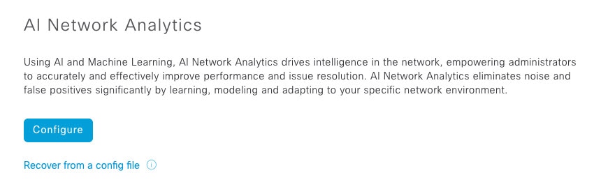
|
| Step 3 |
Do one of the following:
|
| Step 4 |
In the Success dialog box, click Okay. |
| Step 5 |
(Recommended) In the AI Network Analytics window, click Download Configuration file. |
To disable Cisco AI Network Analytics data collection, you must turn off (disable) the connection to the Cisco AI Network Analytics cloud service. This will disable all of the Cisco AI Network Analytics-related features, such as AI-Driven Issues, Network Heatmap, Site Comparison, and Peer Comparison.
| Step 1 |
In the Cisco DNA Center GUI, click the Menu icon ( |
| Step 2 |
Scroll down to External Services and choose Cisco AI Analytics. |
| Step 3 |
In the Cloud Connection area, click the button to off, such that |
| Step 4 |
Click Update. |
| Step 5 |
To delete your network data from the Cisco AI Network Analytics cloud, contact the Cisco Technical Response Center (TAC) and open a support request. |
| Step 6 |
(Optional) If you have misplaced your previous configuration, click Download configuration file. |
Machine Reasoning knowledge packs are step-by-step workflows that are used by the Machine Reasoning Engine (MRE) to identify security issues and improve automated root cause analysis. These knowledge packs are continuously updated as more information is received. The Machine Reasoning Knowledge Base is a repository of these knowledge packs (workflows). To have access to the latest knowledge packs, you can either configure Cisco DNA Center to automatically update the Machine Reasoning Knowledge Base on a daily basis, or you can perform a manual update.
| Step 1 |
In the Cisco DNA Center GUI, click the Menu icon ( |
| Step 2 |
Scroll down to External Services and choose Machine Reasoning Knowledge Base.
When there is a new update to the Machine Reasoning Knowledge Base, the AVAILABLE UPDATE area appears in the Machine Reasoning Knowledge Base window, which provides the Version and Details about the update.
|
| Step 3 |
(Recommended) Check the AUTO UPDATE check box to automatically update the Machine Reasoning Knowledge Base. You can perform an automatic update only if Cisco DNA Center is successfully connected to the Machine Reasoning Engine in the cloud. |
| Step 4 |
To manually update the Machine Reasoning Knowledge Base in Cisco DNA Center, do one of the following:
|
You can view the Cisco DNA Center GUI screens in English (the default), Chinese, Japanese, or Korean.
To change the default language, perform the following task:
| Step 1 |
In your browser, change the locale to one of the supported languages: Chinese, Japanese, or Korean.
|
| Step 2 |
Log in to Cisco DNA Center. The GUI screens are shown in the selected language. 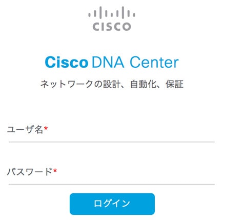 |
Assurance supports role-based access control (RBAC), which enables a user with SUPER-ADMIN-ROLE privileges to define custom roles that permit or restrict users access to certain Assurance features.
For more information see the "Manage Users" chapter in the Cisco DNA Center Administrator Guide.
Use this procedure to define a custom role and then assign a user to that role.
Only a user with SUPER-ADMIN-ROLE permissions can perform this procedure.
| Step 1 |
Define a custom role.
|
| Step 2 |
To assign a user to the custom role you just created, click Add Users. The window appears, which allows you to assign the custom role to an existing user or to a new user.
|
| Step 3 |
If you are an existing user who was logged in when the administrator was making changes to your access permissions, you must log out of Cisco DNA Center and then log back in for the new permission settings to take effect. |
 icon for the device.
 icon in the top-right corner, and then choose
  icon in the top-right corner, and then choose
  Feedback