Limitations and restrictions of Assurance
Assurance does not support devices that are connected through Network Address Translation (NAT).
The documentation set for this product strives to use bias-free language. For the purposes of this documentation set, bias-free is defined as language that does not imply discrimination based on age, disability, gender, racial identity, ethnic identity, sexual orientation, socioeconomic status, and intersectionality. Exceptions may be present in the documentation due to language that is hardcoded in the user interfaces of the product software, language used based on RFP documentation, or language that is used by a referenced third-party product. Learn more about how Cisco is using Inclusive Language.
Assurance does not support devices that are connected through Network Address Translation (NAT).
Before you begin using the Assurance application, you must set up Catalyst Center to use Assurance.
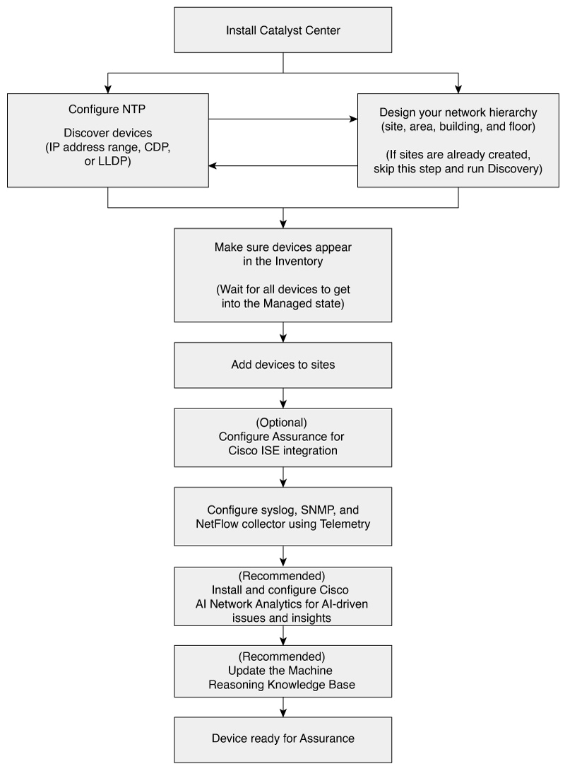
This chapter provides the basic tasks you must do to set up Assurance. Use this chapter in conjunction with the Cisco Catalyst Center User Guide.
See this illustration and the procedure that follows to understand the basic workflow.
|
Step 1 |
Install Catalyst Center. |
||||
|
Step 2 |
Do these tasks in any order:
|
||||
|
Step 3 |
Make sure that the devices appear in the device Inventory. See Display information about your inventory.
|
||||
|
Step 4 |
Add devices to sites. |
||||
|
Step 5 |
If you have APs, we recommend that you add them to a floor map. |
||||
|
Step 6 |
If your network uses Cisco Identity Services Engine (ISE) for user authentication, you can configure Assurance for Cisco ISE integration. This enables you to see more information about wired clients, such as the username and operating system, in Assurance. |
||||
|
Step 7 |
Configure the syslog, SNMP traps, and NetFlow Collector servers using Telemetry. |
||||
|
Step 8 |
(Recommended) To view AI-driven issues and gain network insights, configure Cisco AI Network Analytics data collection. |
||||
|
Step 9 |
(Recommended) To have access to the latest Machine Reasoning workflows, update the Machine Reasoning Knowledge Base. |
||||
|
Step 10 |
Start using the Assurance application. |
Use the Catalyst Center Discovery feature to scan the devices in your network.
Discovery scans the devices in your network and sends the list of discovered devices to inventory.
Discovery also works with Device Controllability to configure the required network settings on devices when these settings are missing from devices.
There are four ways to discover devices:
Use Cisco Discovery Protocol (CDP) and provide a seed IP address.
Specify a range of IP addresses. You can include up to 4096 devices in the range.
Use Link Layer Discovery Protocol (LLDP) and provide a seed IP address.
Use Classless Inter-Domain Routing (CIDR) and provide a seed IP address.
When you configure the Discovery criteria, you can use settings to reduce the time needed to discover devices:
CDP Level and LLDP Level: If you use CDP or LLDP as the Discovery method, you can set the CDP or LLDP level to indicate the number of hops from the seed device that you want to scan. The default, level 16, might take a long time on a large network. If you need to discover fewer devices, set the level to a lower value.
Prefix Length: If you use CIDR as a discovery method, you can set the prefix length value, which ranges from 20 to 30. The default value is 30.
Subnet Filters: If you use an IP address range, you can specify devices in specific IP subnets for Discovery to ignore.
Preferred Management IP: Whether you use CDP, LLDP, CIDR, or an IP address range, you can specify whether you want Catalyst Center to add any of the device's IP addresses or only the device loopback address.
 Note |
For Cisco SD-Access Fabric and Cisco Catalyst Assurance, specify the device loopback address. |
Regardless of the method you use, you must be able to reach the device from Catalyst Center and configure specific credentials and protocols in Catalyst Center to discover your devices. These credentials can be configured and saved in the window or on a per job basis in the Discovery window.
Note |
If a device uses a first hop resolution protocol, such as Hot Standby Router Protocol (HSRP) or Virtual Router Redundancy Protocol (VRRP), the device can be discovered and added to the inventory along with its floating IP address. Later, if HSRP or VRRP fails, the IP address might be reassigned to a different device. This situation can cause issues with the data that Catalyst Center retrieves for analysis. |
Before you run Discovery, complete these minimum prerequisites:
Understand what devices will be discovered by Catalyst Center by viewing the Cisco Catalyst Center Compatibility Matrix.
Understand that the preferred network latency between Catalyst Center and devices is 100 ms round-trip time (RTT). (The maximum latency is 200 ms RTT.)
Ensure that at least one SNMP credential is configured on your devices for use by Catalyst Center. At a minimum, this configuration can be an SNMPv2C read credential.
To allow Catalyst Center to discover and manage devices, configure SSH credentials on them. Catalyst Center discovers and adds a device to its inventory if at least one of these criteria is met:
The account that is being used by Catalyst Center to SSH into your devices has privileged EXEC mode (level 15).
You configure the device’s enable password as part of the CLI credentials configured in the Discovery job. For more information, see Discovery configuration guidelines and limitations.
When Catalyst Center discovers a device, it uses one of the device IP addresses as the preferred management IP address. The IP address can be that of a built-in management interface of the device, another physical interface, or a logical interface such as Loopback0. You can configure Catalyst Center to use the device loopback IP address as the preferred management IP address, provided the IP address is reachable from Catalyst Center.
When you select Use Loopback IP as the preferred management IP address, Catalyst Center determines the preferred management IP address as detailed in this table:
|
If |
Then |
|---|---|
|
If the device has one loopback interface |
Catalyst Center uses that loopback interface IP address. |
|
If the device has multiple loopback interfaces |
Catalyst Center uses the loopback interface with the highest IP address. |
|
If there is no loopback interface |
Catalyst Center uses the Ethernet interface with the highest IP address. (Subinterface IP addresses are not considered.) The system also uses the loopback interface with the highest IP address. |
|
If there are no Ethernet interfaces |
Catalyst Center uses the serial interface with the highest IP address. |
After a device is discovered, you can update the management IP address from the Inventory window.
This section describes the limitations and guidelines of device discovery.
These are the guidelines and limitations for Catalyst Center to discover your Cisco Catalyst 3000 Series Switches and Catalyst 6000 Series Switches:
Configure the CLI username and password with privileged EXEC mode (level 15). These credentials are the same CLI username and password that you configure in Catalyst Center for the Discovery function. Catalyst Center requires the highest access level to the device.
Explicitly specify the transport protocols allowed on individual interfaces for both incoming and outgoing connections. Use the transport input and transport output commands for this configuration. For information about these commands, see the command reference document for the specific device type.
Don’t change the default login method for a device's console port and the VTY lines. If a device is already configured with a AAA (TACACS) login, make sure that the CLI credential defined in the Catalyst Center is the same as the TACACS credential defined in the TACACS server.
These are the guidelines and limitations for Catalyst Center to discover your wireless controllers and APs:
Cisco Wireless Controllers must be discovered using the management IP address instead of the service port IP address. If not, the related wireless controller 360 and AP 360 windows won’t display any data.
After the wireless controllers are discovered, Catalyst Center displays the list of associated APs in the inventory. The listed APs are connected to the wireless controller either during the discovery or through inventory sync.
Note |
For any new APs that join the wireless controller after the inventory sync:
|
Third-party devices can’t be discovered with the Catalyst Center discovery feature. You must add the third-party devices manually to your network. For more information, see "Add a Third-Party Device" in the Cisco Catalyst Center User Guide.
Discovery credentials are the CLI, SNMPv2c, SNMPv3, HTTP, HTTPS, and NETCONF configuration values for the devices that you want to discover. You must specify the credentials based on the types of devices you are trying to discover:
Network devices: CLI and SNMP credentials.
Note |
For NETCONF-enabled devices such as embedded wireless controllers, you must specify SSH credentials with admin privilege and select the NETCONF port. |
Compute devices (NFVIS): CLI, SNMP, HTTP, and HTTPS credentials.
Because the various devices in a network can have different sets of credentials, you can configure multiple sets of credentials in Catalyst Center. The discovery process iterates through all sets of credentials that are configured for the Discovery job until it finds a set that works for the device.
If you use the same credential values for the majority of devices in your network, you can configure and save them to reuse in multiple Discovery jobs. To discover devices with unique credentials, you can add job-specific Discovery credentials when you run Discovery jobs. You can configure up to 10 global credentials for each credential type and define any five of them. If you need to define a job-specific credential, you can define five global credentials and one job-specific credential for each credential type.
To define credentials for a Discovery, click the menu icon and choose . To continue, use these procedures and discovery credential information:
| Field | Description | ||
|---|---|---|---|
| Name/Description |
Name or phrase that describes the CLI credentials. If authentication fails for CLI, Catalyst Center retries the authentication process for 300 seconds (5 minutes). |
||
| Username |
Name that is used to log in to the CLI of the devices in your network. |
||
| Password |
Password that is used to log in to the CLI of the devices in your network. For security reasons, re-enter the password as confirmation.
|
||
| Enable Password |
Password used to move to a higher privilege level in the CLI. Configure this password only if your network devices require it. For security reasons, re-enter the enable password.
|
| Field | Description | ||
|---|---|---|---|
|
Read |
|
||
|
Write |
|
| Field | Description | ||
|---|---|---|---|
|
Name/Description |
Name or description of the SNMPv3 settings that you are adding. |
||
| Username |
Name associated with the SNMPv3 settings. |
||
|
Mode |
Security level that an SNMP message requires. Select one of these modes:
|
||
|
Auth. Type |
Authentication type to be used. (Enabled if you select Authentication and Privacy or Authentication, No Privacy as Mode.) Select one of these authentication types:
|
||
|
Auth. Password |
SNMPv3 password used for gaining access to information from devices that use SNMPv3. These passwords (or passphrases) must be at least eight characters in length.
|
||
|
Privacy Type |
Privacy type. (Enabled if you select Authentication and Privacy as Mode.) Select one of these privacy types:
|
||
|
Privacy Password |
SNMPv3 privacy password that is used to generate the secret key for encrypting messages that are exchanged with devices that support encryption standards. Passwords (or passphrases) must be at least eight characters long.
|
| Field | Description |
|---|---|
| Retries | Number of times Catalyst Center tries to communicate with network devices using SNMP. |
| Timeout (in Seconds) | Amount of time, in seconds, between retries. |
| Field | Description | ||
|---|---|---|---|
|
Type |
Specifies the kind of HTTPS credentials you are configuring. Valid types are Read or Write. |
||
|
Read |
You can configure up to 10 HTTPS read credentials:
The password must contain between 7 and 128 characters, including at least one of these characters:
|
||
|
Write |
You can configure up to 10 HTTPS write credentials:
The password must contain between 7 and 128 characters, including at least one of these characters:
|
| Field | Description |
|---|---|
|
Port |
Port on the device. You can use one of these ports:
If authentication fails for NETCONF, Catalyst Center retries the authentication process for 300 seconds (5 minutes). |
You can discover devices using Cisco Discovery Protocol (CDP), an IP address range, CIDR, or LLDP. This procedure shows you how to discover devices and hosts using CDP. For more information about the other discovery methods, see Discover your network using an IP address range or CIDR and Discover your network using LLDP.
Note |
|
Enable CDP on your network devices.
Configure your network devices, as described in Discovery prerequisites.
Configure your network device's host IP address as the client IP address. (A host is an end-user device, such as a laptop computer or mobile device.)
|
Step 1 |
From the main menu, choose . |
|
Step 2 |
In the Discovery window, click Add Discovery. |
|
Step 3 |
In the Discover Devices window, complete these fields:
|
|
Step 4 |
In the Provide Credentials window, configure the discovery credentials and other settings as required. Enter at least one CLI credential and one SNMP credential for Catalyst Center to configure for the devices it discovers. You can have a maximum of five global credentials and one task-specific credential for each type. For more details, see Discovery credentials. |
|
Step 5 |
In the Schedule Job window, do these steps: |
|
Step 6 |
In the Summary window, review the configuration settings. (To make any changes, click Edit.) |
|
Step 7 |
Click Start Discovery. You can view the status of the task in the window. |
The Device Discovery window displays an option to view the discovered devices based on the site assignment. Use this option to view devices assigned to a site or a network or the unassigned devices in the inventory.
You can discover devices and hosts using an IP address range, CIDR, CDP, or LLDP. This procedure explains how to perform discovery using an IP address range or CIDR. For more information about the other Discovery methods, see Discover your network using CDP, and Discover your network using LLDP.
Your devices must have the required device configurations, as described in Discovery prerequisites.
|
Step 1 |
From the main menu, choose . |
||
|
Step 2 |
In the Discovery window, click Add Discovery. |
||
|
Step 3 |
In the Discover Devices window, complete these fields:
|
||
|
Step 4 |
In the Provide Credentials window, configure the discovery credentials and other settings as required. Enter at least one CLI credential and one SNMP credential for Catalyst Center to configure for the devices it discovers. You can have a maximum of five global credentials and one task-specific credential for each type. For more details, see Discovery credentials. |
||
|
Step 5 |
In the Schedule Job window, do these steps: |
||
|
Step 6 |
In the Summary window, review the configuration settings. (To make any changes, click Edit.) |
||
|
Step 7 |
Click Start Discovery. The status of the task displays in the window. |
The Device Discovery window displays an option to view the discovered devices based on the site assignment. Use this option to view devices assigned to a site or a network or the unassigned devices in the inventory.
You can discover devices using Link Layer Discovery Protocol (LLDP), CDP, CIDR, or an IP address range. This procedure describes how to discover devices and hosts using LLDP. For more information about the other discovery methods, see Discover your network using CDP and Discover your network using an IP address range or CIDR.
Note |
|
Enable the LLDP protocol on your network devices.
Configure your network devices according to Discovery prerequisites.
Configure your network device host IP address as the client IP address. A host is an end-user device, such as a laptop computer or mobile device.
|
Step 1 |
From the main menu, choose . |
|
Step 2 |
In the Discovery window, click Add Discovery. |
|
Step 3 |
In the Discover Devices window, complete these fields:
|
|
Step 4 |
In the Provide Credentials window, configure the discovery credentials and other settings as required. Enter at least one CLI credential and one SNMP credential for Catalyst Center to configure for the devices it discovers. You can have a maximum of five global credentials and one task-specific credential for each type. For more details, see Discovery credentials. |
|
Step 5 |
In the Schedule Job window, do these steps: |
|
Step 6 |
In the Summary window, review the configuration settings. (To make any changes, click Edit.) |
|
Step 7 |
Click Start Discovery. You can view the status of the task in the window. |
The Device Discovery window displays an option to view the discovered devices based on the site assignment. Use this option to view devices assigned to a site or a network or the unassigned devices in the inventory.
These sections provide information about how to manage the Discovery jobs.
|
Step 1 |
From the main menu, choose . |
|
Step 2 |
To stop an active Discovery job, hover your cursor over the ellipsis icon ( |
|
Step 3 |
To restart an inactive Discovery job, hover your cursor over the ellipsis icon in the Actions column and select Re-discover. |
You can clone a Discovery job to retain all the information defined for that job.
Run at least one Discovery job.
|
Step 1 |
From the main menu, choose . |
|
Step 2 |
To copy a Discovery job, hover your cursor over the ellipsis icon ( Catalyst Center creates a copy of the Discovery job named "Clone of Discovery_Job ." |
|
Step 3 |
(Optional) To change the name of the Discovery job, replace the default name in the Discovery Name field with a new name. |
|
Step 4 |
Define or update the parameters for the new Discovery job. |
You can delete a Discovery job regardless of whether it is active or inactive.
|
Step 1 |
From the main menu, choose . |
|
Step 2 |
To delete a Discovery job, hover your cursor over the ellipsis icon ( |
|
Step 3 |
Click OK to confirm. |
You can view information about a Discovery job, such as the settings and credentials that were used. You also can view the historical information about each Discovery job that was run, including information about the specific devices that were discovered or that failed to be discovered.
Run at least one Discovery job.
|
Step 1 |
From the main menu, choose . |
|
Step 2 |
In the Discovery window, click All discoveries page from previous release. |
|
Step 3 |
In the left Discoveries pane, select the Discovery job. Alternatively, use the Search function to find a Discovery job by device IP address or name. |
|
Step 4 |
Click the down arrow next to one of these areas for more information:
|
You can create a network hierarchy that represents the geographical locations of your network.
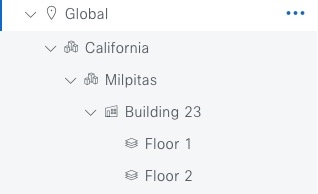
The network hierarchy is organized in a hierarchical structure. This hierarchy consists of sites. A site may refer to an area, building, or floor. The placement of each site in the hierarchical structure depends on network hierarchy rules. See this figure and table to learn how you can structure different sites in your network hierarchy.
|
Site types |
Description |
Rule |
||
|---|---|---|---|---|
|
Global ( |
The default site element under which all other site elements reside. |
Only areas and buildings can reside directly under Global. |
||
|
Areas ( |
Areas identify a geographic region. They provide a way to group areas, buildings, or both areas or buildings. Therefore, they do not have a physical address. |
Areas can reside directly under Global or other areas. |
||
|
Buildings ( |
Buildings can have physical addresses or latitude and longitude coordinates. |
Buildings can reside directly under Global or areas. They cannot contain areas, but they can contain floors. |
||
|
Floors ( |
Floors can be added to buildings with or without maps that contain various building components, like walls and windows. Floor maps allow you to visualize the wireless network coverage of your wireless devices positioning on the floor. You can manually create them or import them from files, such as DXF, DWG, JPG, GIF, PNG, or PDF file types. |
Only floors reside under buildings.
|
The hierarchical organization of the network hierarchy allows you to easily apply design settings or configurations to a specific hierarchical site. For example, you can apply design settings to an entire area or to only a floor.
 Tip |
Naming hierarchical sites can help you identify where to apply design settings later. |
To get started, build your network hierarchy using one of these methods:
Create the network hierarchy. For more information, see Create the network hierarchy.
Import an existing network hierarchy from Cisco Prime Infrastructure or Ekahau Pro. For more information, see Use an existing Cisco network hierarchy or Use an existing Ekahau network hierarchy.
Create the network hierarchy by creating new areas, buildings, and floors.
Catalyst Center allows you to easily define physical sites and then specify common resources for those sites. The Design area uses a hierarchical format for intuitive use, while eliminating the need to redefine the same resource in multiple places when provisioning devices. By default, there is one site called Global. You can add more sites, buildings, and areas to your network hierarchy. You must create at least one site before you can use the provision features.
|
Step 1 |
From the main menu, choose . A world map appears in the right pane. |
||||||||
|
Step 2 |
From this window, you can add, edit, and delete sites. See this table for details.
|
|
Step 1 |
From the main menu, choose . |
||||||||
|
Step 2 |
From this window, you can add, edit, and delete a building. See this table for details.
|
After you add a building, you can add floors to it. You can add a basic floor that doesn't have a floor map and add the floor map later, or you can add a floor and include a floor map at the same time.
To add a basic floor to a building, use this procedure.
To add a floor and a floor map at the same time, see the Cisco Catalyst Center User Guide.
|
Step 1 |
From the main menu, choose . |
||||||||
|
Step 2 |
From this window, you can add, edit, and delete a floor. See this table for details.
|
If you have an existing network hierarchy in Cisco Prime Infrastructure, you can export it and then import it into Catalyst Center, saving time and effort spent in creating a new network hierarchy.
This information is available for you to re-create your network hierarchy:
Site Hierarchy: Your existing site hierarchy is downloaded in a CSV file format. The CSV file contains details such as site names, parent hierarchy, number of floors, location, and site address.
Map Archive: Map information is downloaded as a map archive in a TAR file format. The map archive file contains data such as the date and time, number of floors, and APs. Depending on what you decide to download, the map archive can also include map information, such as floor dimensions (length, width, and height) and details about the APs and overlay objects that have been placed on the floor maps. You can also decide to download calibration information, such as the RF attenuation model that has been applied to each floor.
To base the map archive on the global hierarchy or the hierarchy of a single site, building, or floor:
Site: The chosen site and all of its subsites, buildings, and floors are exported.
Building: The chosen building and all of its floors are exported.
Floor: The chosen floor is exported.
Note |
Catalyst Center supports the United States' Federal Information Processing Standards (FIPS). FIPS is an optional mode that can be enabled when installing the Catalyst Center image. By default, FIPS mode is disabled. |
FIPS mode has an impact on the export and import of map archives.
If FIPS mode is enabled:
Exported map archives are unencrypted.
Only unencrypted map archives can be imported.
If FIPS mode is disabled:
Exported map archives are encrypted.
Both encrypted and unencrypted map archives can be imported.
For details, see the Cisco Catalyst Center User Guide.
You can export your site hierarchy from Cisco Prime Infrastructure in a CSV file format. The CSV file contains details such as site names, parent hierarchy, number of floors, location, and site address.
Site hierarchy export is supported in Cisco Prime Infrastructure, Release 3.2 and later.
|
Step 1 |
In Cisco Prime Infrastructure, choose . |
|
Step 2 |
In the Device Groups window, click Export Groups. |
|
Step 3 |
In the Export Groups dialog box, click the APIC-EM radio button. |
|
Step 4 |
To download the CSV file, click OK. |
You can export map archive files from Cisco Prime Infrastructure and import them into Catalyst Center. Map archives contain map information, such as floor dimensions, and calibration information, such as the Radio Frequency (RF) attenuation model that has been applied to each floor in Cisco Prime Infrastructure.
|
Step 1 |
From the Cisco Prime Infrastructure GUI, choose . |
|
Step 2 |
From the Export drop-down list, select Map Archive. The Export Map Archive window opens, and the Select Sites window opens by default. |
|
Step 3 |
Check the check box adjacent to a specific site, campus, building, or floor that you want to export. Alternatively, check the Select All check box to export all the maps. |
|
Step 4 |
Select at least one of these options:
|
|
Step 5 |
Click Generate Map Archive. This message shows the progress of the operation: Exporting data is in progressA TAR file is created and is saved to your local machine. |
|
Step 6 |
Click Done. |
You can import a site hierarchy that you exported from Cisco Prime Infrastructure as a CSV file. For information about exporting the site hierarchy, see the Cisco Catalyst Center User Guide.
Make sure that you have Cisco Wireless Controllers and APs in your Catalyst Center inventory. If not, discover them using the Discovery feature.
Add and position APs on a floor map.
If you manually created sites in Catalyst Center that are present in Cisco Prime Infrastructure, you must remove them from Catalyst Center before you can import them.
|
Step 1 |
From the main menu, choose . |
||
|
Step 2 |
From the map toolbar, click Import and select Import Sites. |
||
|
Step 3 |
In the dialog box, click one of these radio buttons:
|
||
|
Step 4 |
In the dialog box, drag and drop your CSV file into the download area. Alternatively, you can click Choose a file, navigate to where your CSV file is located, and then click Import.
|
You can import a map archive TAR file into Catalyst Center. For example, you can upload the TAR file that you exported from Cisco Prime Infrastructure.
Note |
Catalyst Center supports the United States' Federal Information Processing Standards (FIPS). FIPS is an optional mode that can be enabled when installing the Catalyst Center image. By default, FIPS mode is disabled. |
For information about exporting site hierarchy, see Export your map archive from Cisco Prime Infrastructure.
|
Step 1 |
From the main menu, choose . |
|
Step 2 |
From the map toolbar, click Import and select Import Floor Maps. |
|
Step 3 |
In the Import Floor Maps dialog box, drag and drop the map archive file. |
|
Step 4 |
Click Import. The map archive file is imported. |
The Ekahau Pro tool allows you to create a complete network plan for your enterprise, including floor layout, AP locations, and obstacles. After creating the floor layout, you can export the simulated network plan as an Ekahau project file. You can also export the real-world site survey data into a format that Catalyst Center can use.
To augment the preconfigured working floors, the Catalyst Center allows you to export the working floors from Catalyst Center as an Ekahau project and import the project into the Ekahau Pro Tool.
|
Step 1 |
From the main menu, choose . A world map displays in the right pane. |
|
Step 2 |
In the left pane, select the desired site, building, or floor. |
|
Step 3 |
To export a complete network map as an Ekahau project, from the Export drop-down list, select Export Floor Maps. To export an Ekahau project of a site, building, or floor map, from the left pane, hover your cursor over the ellipsis The Export Floor Maps dialog box is displayed. |
|
Step 4 |
In the Export Floor Maps dialog box, select the Ekahau Project export format. |
|
Step 5 |
Click Export. An ESX file is created and saved to your local machine. |
|
Step 6 |
Import the ESX file into the Ekahau Pro tool, augment the floor, and save the file. |
|
Step 7 |
Import the Ekahau project into the Catalyst Center under the site. For more information, see Import an Ekahau project to Catalyst Center. |
Importing an Ekahau Cloud project can fail if the project has local changes (such as removing an AP or wall), that are out-of-sync with the Ekahau Cloud project. To avoid this situation, make sure to synchronize any local changes to the Ekahau Cloud before importing the Ekahau Cloud project to Catalyst Center.
For the Ekahau versions that Catalyst Center supports, see the Compatibility Matrix. Ekahau releases new versions periodically. For information about importing a later version than Ekahau 11.0.2, see the Ekahau support article titled How to import Ekahau data into the Cisco Catalyst Center.
|
Step 1 |
From the main menu, choose . |
||
|
Step 2 |
Design your network hierarchy by adding sites, buildings, and floors.
|
||
|
Step 3 |
In the left pane, hover your cursor over the ellipsis The Import Ekahau Project dialog box appears. |
||
|
Step 4 |
Drag and drop the ESX file into the boxed area in the Import Ekahau Project dialog box, or click the click to select link and browse to the ESX file.
|
||
|
Step 5 |
If an AP is not found in the inventory and remains unmapped, the planned AP is retained on the floor. To see the reason for the mismatch, hover your cursor over the planned AP icon on the floor map, and click Import History. These attempts are made to map the planned APs to real APs:
|
||
|
Step 6 |
To manually assign the planned AP to a real AP, hover your cursor over the planned AP icon on the floor map, and click . The Assign Planned APs panel appears. |
||
|
Step 7 |
In the Assign Planned APs panel, map the planned AP to a real AP by AP name, AP type, or All APs. |
||
|
Step 8 |
Click the radio button next to the AP Name, and click Assign to manually assign the planned AP. |
||
|
Step 9 |
Click Save. |
To create your network hierarchy, you can upload an Ekahau site survey file and an AP mapping file (in CSV format).
The Ekahau site survey only contains the floor map with the APs known by name and position on the map. By default the AP model might not be set in the Ekahau site survey. A pre-requisite of importing to Catalyst Center is to open the project in Ekahau and configure the AP models using Ekahau-allowed model names, for example, Cisco C9130i for the Catalyst Center 9130 AP.
Because the Ekahau site survey doesn't provide Catalyst Center with any information about the radios of each AP, the AP mapping file augments the Ekahau site survey with this information. The AP mapping file is limited in that you can only provide the desired AP mapping by AP model, not by AP name. So, if you have multiple APs of the same type but different antenna configurations, only one antenna configuration can be applied to all APs of that type within the project.
For each AP in the AP mapping file, you define the model number followed by the configuration of each antenna:
model,antennaName0,antennaAzimuth0,antennaElevation0,antennaName1,antennaAzimuth1,antennaElevation1 For example, this AP mapping file defines the configuration of a Catalyst 9130I with two antennas:
AP9130I,Internal-9130-2.4GHz,90d,0d,Internal-9130-5GHz,90d,0d The model attribute must be the same as the equivalent planned AP model in the Catalyst Center GUI, for example, AP9130I for the Catalyst Center 9130 AP. Similarly, the antennaName attributes must also be the same names found and supported in the Catalyst Center GUI. If the AP has three or more radios, you can continue the n -based numbering pattern of the antennaName , antennaAzimuth , and antennaElevation parameters to define the antenna information for each radio by slot number supported by that AP model.
Catalyst Center includes a CSV template file that you can download and edit to define the required AP antenna information.

If an AP isn't in the Catalyst Center device inventory, it's imported as a planned AP. However, you can use a naming convention so that when you add an AP to the device inventory, Catalyst Center can automatically convert it to an actual AP.
The naming convention is AP, followed by the last four digits of the AP's MAC address, for example, AP-c4:e0. Using this information, Catalyst Center attempts to match the provided digits with the last four digits of an AP's Ethernet MAC or radio MAC address. If this information isn't available or a match is unsuccessful, Catalyst Center attempts to match AP names.
Open the project in Ekahau and configure the AP models using Ekahau-allowed model names, for example, Cisco C9130i for the Catalyst Center 9130 AP.
Create an AP mapping file (CSV format) to provide Catalyst Center with information about the radios of each AP model that is being used.
|
Step 1 |
From the main menu, choose Design > Network Hierarchy. |
||
|
Step 2 |
Click Add Site > Add Area. Alternatively, you can hover your cursor over the ellipsis |
||
|
Step 3 |
In the left pane, hover your cursor over the ellipsis |
||
|
Step 4 |
In the Import Ekahau Survey dialog box, drag and drop the Ekahau Survey file into the Ekahau Survey boxed area, or click the Choose a file link and browse to the ESX file. |
||
|
Step 5 |
Drag and drop the CSV file into the AP Mapping CSV boxed area, or click the Choose a file link and browse to the CSV file.
|
||
|
Step 6 |
Click Import. After the files are successfully downloaded, a success message appears. |
||
|
Step 7 |
Click View Hierarchy and navigate to the floors to verify that the devices have been imported and positioned properly. Hover the cursor over a device to view its details. |
In 2D maps, you can configure devices and overlay objects on your floor maps. The Cisco Catalyst Assurance User Guide provides basic guidance on working with 2D maps. In addition to 2D maps, Catalyst Center supports 3D maps with more capabilities. For a full description of both 2D and 3D map features, see the Cisco Catalyst Center User Guide.
APs: An access point (AP) serves as the connection point between wireless and wired networks or as the center point of a standalone wireless network. In 2D maps, an AP represents an actual, installed device. For a list of APs that Catalyst Center supports, see the Cisco Catalyst Center Compatibility Matrix.
Planned APs: Planned APs are representations of APs that haven’t been installed yet. By placing planned APs on a map, you can envision your wireless network RF coverage and make changes before you actually install the APs.
Sensors: A sensor is a dedicated Cisco Aironet 1800S Active Sensor that gets bootstrapped using Cisco PnP. After it obtains the Assurance server reachability details, it communicates directly with the Assurance server. For more details, including information about sensor tests, see the Manage Sensors and Sensor-Driven Tests.
Coverage Areas: By default, any area defined as part of a floor map is considered as a wireless coverage area. However, if you have a building that is nonrectangular or you want to mark a nonrectangular or polygon-shaped area on a floor, you can use the Coverage Areas drawing tool to create a coverage area.
Openings: An opening, also called an atrium, is an open-air or skylight-covered area within a building. An opening can extend through multiple floors and can affect wireless signal coverage areas.
Location Regions: Location regions are used by location services (Cisco CMX or Cisco Spaces). Location regions define areas that are included in or excluded while positioning clients. Inclusion areas are included in the calculations and exclusion areas aren’t included. When you create a floor, by default, the whole region on the floor is defined as the inclusion region. You can manually edit the default inclusion region and set exclusion regions on the floor. For example, you can exclude areas such as openings or atriums, and large racks within a building, where positioning of real clients isn’t possible.
Walls: Walls define any exterior or interior vertical structures in a building, such as windows, cubicles, and doors. Because they can be made of different materials and have different densities, they can significantly impact RF signal attenuation and heatmap calculation. For example, the more walls you include in a floor map, the longer it can take to compute a heatmap. Although, even if you have a high number of walls on your floormap, you can adjust the number used to compute the heatmap. For information, see "2D Map View Options" and "3D Map View Options" in the Cisco Catalyst Center User Guide.
Shelving Units: Shelving units are obstacles that can significantly impact RF signal attenuation and heatmap calculation. A high-ceiling warehouse is an example of a location with shelving units.
Markers: A marker identifies a location on a map. When you create a marker, you can name it and position it to help you identify it later.
GPS Markers: When integrated with Catalyst Center, location services, such as Cisco Spaces or Cisco Connected Mobile Experiences (CMX), use GPS markers to calculate the approximate geographical location of clients.
Align Points: Align points are markers that are used to position multiple floors that have different physical shapes. In 3D maps, floors are aligned at the top-left corner of the map (point 0,0). If you manage each floor independently, the misalignment isn’t a problem. However, to use some of the features of 3D maps, the floors need to be aligned as they are in reality. To compensate for this misalignment, you can insert one or more align points on two or more floors, so that the floors align properly one on top of the other in a 3D map.
|
Step 1 |
From the main menu, choose . |
||||||||||
|
Step 2 |
In the left hierarchy tree, select a floor. |
||||||||||
|
Step 3 |
From the map toolbar, click . By default, the Devices and Access Points toggle buttons are chosen. |
||||||||||
|
Step 4 |
From this window, you can add, position, edit, and remove APs. See this table for details.
|
Make sure you have the Cisco AP 1800S sensor in your inventory. The Cisco Aironet 1800s Active Sensor must be provisioned using Plug and Play for it to show up in the Inventory.
|
Step 1 |
From the main menu, choose . |
||||||
|
Step 2 |
From the left hierarchy tree, select a floor. |
||||||
|
Step 3 |
From the map toolbar, click . |
||||||
|
Step 4 |
From this window, you can add, position, edit, and remove sensors. See this table for details.
|
This procedure shows you how to mark a nonrectangular or polygon-shaped area as a coverage area on a floor map.
For more information about coverage areas, see Configure 2D floor map devices and overlay objects.
|
Step 1 |
From the main menu, choose . |
|
Step 2 |
From the left hierarchy tree, select a floor. |
|
Step 3 |
In the map toolbar, click . |
|
Step 4 |
To add a coverage area, do these tasks: |
|
Step 5 |
To edit a coverage area, do these tasks:
|
|
Step 6 |
To delete a coverage area, do these tasks:
|
|
Step 7 |
In the map toolbar, click Save. |
Creating an opening is similar to creating an open space or atrium on a floor. On multifloor buildings, typically the opening extends vertically through multiple floors. This procedure shows you how to add, edit, and remove openings on a floor map. It also shows you how to copy openings to other floors.
For more information about openings, see Configure 2D floor map devices and overlay objects.
|
Step 1 |
From the main menu, choose . |
|
Step 2 |
From the left hierarchy tree, select a floor. |
|
Step 3 |
In the map toolbar, click . |
|
Step 4 |
To add an opening: |
|
Step 5 |
To edit an opening:
|
|
Step 6 |
To copy an opening from one floor to another:
|
|
Step 7 |
To remove an opening:
|
|
Step 8 |
In the map toolbar, click Save. |
Location regions are areas on the map that are either included in or excluded from the heatmap calculation. These topics show you how to add, edit, and remove location regions.
This procedure shows you how to add, edit, and remove an inclusion region. Use these guidelines to define an inclusion region on a floor map:
Inclusion regions can be any polygon-shaped area and must have at least three points.
You can only define one inclusion region on a floor. By default, an inclusion region is defined for each floor area when it is created. The inclusion region is indicated by a solid aqua line, and generally outlines the entire floor area.
For more information about inclusion regions, see Configure 2D floor map devices and overlay objects.
|
Step 1 |
From the main menu, choose . |
|
Step 2 |
From the left hierarchy tree, select a floor. |
|
Step 3 |
In the map toolbar, click . |
|
Step 4 |
In the left pane of the map, click the Inclusion icon. |
|
Step 5 |
To create an inclusion region, use the drawing tool: |
|
Step 6 |
To edit the location of an inclusion region, drag and drop the shape to the new location. |
|
Step 7 |
To remove an inclusion region, right-click the shape and select Remove. |
|
Step 8 |
In the map toolbar, click Save. |
This procedure shows you how to add, edit, and remove an exclusion region. Use these guidelines to define exclusion regions on a floor map:
Exclusion regions can be any polygon-shaped area and must have at least three points.
Exclusion regions are defined within the borders of an inclusion region.
You can define multiple exclusion regions on a floor map.
For more information about exclusion regions, see Configure 2D floor map devices and overlay objects.
|
Step 1 |
From the main menu, choose . |
|
Step 2 |
From the left hierarchy tree, select a floor. |
|
Step 3 |
In the map toolbar, click . |
|
Step 4 |
From the left pane of the map, click the Exclusion icon. |
|
Step 5 |
To create an exclusion region, use the drawing tool: |
|
Step 6 |
To edit the location of an exclusion region, drag and drop the shape to the new location. |
|
Step 7 |
To remove an exclusion region, right-click the shape and select Remove. |
|
Step 8 |
In the map toolbar, click Save. |
This procedure shows you how to add, edit, move, and remove walls on a floor map.
For information about how walls impact RF signal attenuation and heatmap calculation, see Configure 2D floor map devices and overlay objects.
|
Step 1 |
From the main menu, choose . |
|
Step 2 |
From the left hierarchy tree, select a floor. |
|
Step 3 |
In the map toolbar, click . |
|
Step 4 |
To add walls: |
|
Step 5 |
To change a wall type, and depending on the wall type also configure its parameters: |
|
Step 6 |
To move a wall: |
|
Step 7 |
To remove a wall, right-click the wall and select Remove. |
|
Step 8 |
In the map toolbar, click Save. |
This procedure shows you how to add, copy, edit, and remove shelving units on a floor map.
For information about shelving units, see Configure 2D floor map devices and overlay objects.
|
Step 1 |
From the main menu, choose . |
|
Step 2 |
From the left hierarchy tree, select a floor. |
|
Step 3 |
In the map toolbar, click . |
|
Step 4 |
To add shelving units: |
|
Step 5 |
To create a copy or an array of a shelving unit:
|
|
Step 6 |
To edit the name, dimensions, orientation, and whether it is two-sided, right-click the shelving unit and select Edit. |
|
Step 7 |
To remove a shelving unit, right-click the shelving unit and select Remove. |
|
Step 8 |
In the map toolbar, click Save. |
This procedure shows you how to add, edit, and remove markers.
|
Step 1 |
From the main menu, choose . |
|
Step 2 |
From the left hierarchy tree, select a floor. |
|
Step 3 |
In the map toolbar, click . |
|
Step 4 |
In the left pane of the map, click the Markers icon. |
|
Step 5 |
In the Place Markers dialog box, enter the name for the marker, and click Add. |
|
Step 6 |
To place the marker, click the map where you want to place the marker. |
|
Step 7 |
To move a marker, hover your cursor over the marker until it turns blue. Then drag and drop it in the new location. |
|
Step 8 |
To edit a marker, right-click the marker and select Edit. |
|
Step 9 |
To remove a marker, right-click the marker and select Remove. |
|
Step 10 |
In the map toolbar, click Save. |
This procedure shows you how to add, edit, and remove GPS markers. For more information about GPS markers, see Configure 2D floor map devices and overlay objects.
Note |
The GPS marker is an attribute of the building. You can apply it to all the floors of the building. |
|
Step 1 |
From the main menu, choose . |
|
Step 2 |
From the left hierarchy tree, select a floor. |
|
Step 3 |
In the map toolbar, click . |
|
Step 4 |
To add a GPS marker: |
|
Step 5 |
To edit a GPS marker, right-click the GPS marker and select Edit. |
|
Step 6 |
To move a GPS marker, hover the cursor over the marker until it turns orange. Then drag and drop it in the new location. |
|
Step 7 |
To remove a GPS marker, right-click the GPS marker and select Remove. |
|
Step 8 |
In the map toolbar, click Save. |
This procedure shows you how to add, edit, and remove align points. For more information about align points, see Configure 2D floor map devices and overlay objects.
|
Step 1 |
From the main menu, choose . |
|
Step 2 |
From the left hierarchy tree, select a floor. |
|
Step 3 |
In the map toolbar, click . |
|
Step 4 |
To add an align point:
|
|
Step 5 |
To edit the name of an align point:
|
|
Step 6 |
To change the location of an align point:
|
|
Step 7 |
To remove an align point, right-click the align point and select Remove. |
|
Step 8 |
In the map toolbar, click Save. |
The Inventory function retrieves and saves details, such as host IP addresses, MAC addresses, and network attachment points about devices in its database.
The Inventory function retrieves and saves details, such as host IP addresses, MAC addresses, and network attachment points about devices in its database.
The Inventory feature can also work with the Device Controllability feature to configure the required network settings on devices, if these settings are not already present on the device.
Inventory uses these protocols, as required:
Link Layer Discovery Protocol (LLDP).
IP Device Tracking (IPDT) or Switch Integrated Security Features (SISF). (IPDT or SISF must be enabled on the device.)
LLDP Media Endpoint Discovery. (This protocol is used to discover IP phones and some servers.)
Network Configuration Protocol (NETCONF). For a list of devices, see Discovery prerequisites.
After the initial discovery, Catalyst Center maintains the inventory by polling the devices at regular intervals. The default interval is every 24 hours. However, you can change this interval as required for your network environment. For more information, see Update the device polling interval. Polling occurs for each device, link, host, and interface. Only the devices that have been active for less than one day are displayed. This prevents stale device data, if any, from being displayed. On average, polling 500 devices takes approximately 20 minutes. A configuration change in the device triggers an SNMP trap, which in turn triggers device resynchronization. Device resynchronization is also triggered after the inventory service restart under these circumstances:
If there is an upgrade (Catalyst Center upgrade) after the inventory service restart.
If the device synchronization is in terminated or delayed state after the service restart.
If the Last Sync time for the device is more than 75 percent of the periodic resync interval configured on the device. For example, after the inventory service restart, if the Last Sync time for a device has crossed 18 hours and the configured periodic resync interval is 24 hours, the device will be resynchronized before the periodic resync interval. The percentage for the resync interval cutoff time may vary based on the value configured on the device.
Note |
Points regarding device resynchronization include:
|
You can update the polling interval at the global level for all devices by choosing or at the device level for a specific device by choosing Device Inventory. When you set the polling interval using the Network Resync Interval, that value takes precedence over the Device Inventory polling interval value.
If you do not want a device to be polled, you can disable polling.
Make sure that you have devices in your inventory. If not, discover devices using the Discovery feature.
|
Step 1 |
From the main menu, choose . |
||
|
Step 2 |
Select the devices that you want to update. |
||
|
Step 3 |
From the Actions drop-down list, choose . |
||
|
Step 4 |
In the Edit Device slide-in pane, click Resync Interval. |
||
|
Step 5 |
Select the resync type.
|
||
|
Step 6 |
In the Resync Interval (in Mins) field, enter the time interval (in minutes) between successive polling cycles. |
||
|
Step 7 |
Click Update. |
You can display and filter for information about discovered devices in your inventory. You can also customize or change the information displayed in the Devices table.
Make sure that you have devices in your inventory. If not, discover devices using the Discovery feature.
|
Step 1 |
From the main menu, choose . The Inventory window displays the device information from the discovery process.
If the Inventory window contains APs that don't meet the license requirements, Catalyst Center displays a dialog box with the details. In this dialog box, you have the option to:
|
||||||||||||||||||||||||||||||||||||||||||||||
|
Step 2 |
(Optional) To change the site, click Global and use either the search bar or network hierarchy to find a site. The Inventory window displays the devices available in the chosen site. |
||||||||||||||||||||||||||||||||||||||||||||||
|
Step 3 |
(Optional) To change the Inventory view, use the toggle button ( You can change your default view (the list layout) to other layouts, such as the topology, or map layout. |
||||||||||||||||||||||||||||||||||||||||||||||
|
Step 4 |
(Optional) To change the Devices table focus views, from the Focus drop-down list, select a view, such as Default, Inventory, or Software Images.
|
||||||||||||||||||||||||||||||||||||||||||||||
|
Step 5 |
(Optional) To filter for specific device details in the Devices table, use these filter options.
|
||||||||||||||||||||||||||||||||||||||||||||||
|
Step 6 |
(Optional) To take a guided tour of the Inventory window, click Take a tour in the top-right corner. |
||||||||||||||||||||||||||||||||||||||||||||||
|
Step 7 |
(Optional) To export all the data in the Devices table, click Export in the top-right corner. |
||||||||||||||||||||||||||||||||||||||||||||||
|
Step 8 |
(Optional) To customize the Devices table, click the settings icon (
This table provides key information about specific table columns.
|
||||||||||||||||||||||||||||||||||||||||||||||
|
Step 9 |
(Optional) To manage your devices from the Devices table, you can tag devices, add devices, or use the Actions drop-down list.
|
||||||||||||||||||||||||||||||||||||||||||||||
|
Step 10 |
(Optional) In the Devices table, you can do a variety of actions.
|
In the Inventory window, Catalyst Center indicates the devices for which SSH key verification failed. To deal with this error, complete these steps.
|
Step 1 |
From the main menu, choose . |
||||||||
|
Step 2 |
In the Manageability column, click a device's SSH key verification failed link. |
||||||||
|
Step 3 |
In the dialog box that opens, perform one of these actions:
|
Use this procedure to delete a network device from Catalyst Center.
You can delete devices that aren't a part of the fabric network from the Catalyst Center database.
Note |
|
You must have administrator (ROLE_ADMIN) permissions and access to all devices (RBAC Scope set to ALL) to perform this procedure.
|
Step 1 |
From the main menu, choose . |
||
|
Step 2 |
Check the check box next to the device or devices that you want to delete.
|
||
|
Step 3 |
From the Actions drop-down list, choose .
|
||
|
Step 4 |
(Optional) In the Warning window, check the Config Clean-Up check box. The Device Controllability workflow is triggered. The network settings and telemetry configuration are removed from the selected device. For more information, see "Device Controllability" in the Cisco Catalyst Center Administrator Guide.
|
||
|
Step 5 |
Click OK to confirm the action. |
At the scheduling step of a workflow that supports Visibility and Control of Configurations, complete this procedure to deploy your device configurations immediately or at a later time.
Ensure that you have disabled Visibility and Control of Configurations in the settings.
|
Step 1 |
Click Now or Later. Update the task name if needed.
|
||
|
Step 2 |
On the Performing Initial Checks window, prepare and submit the task for deployment. |
When you reach the scheduling step in a workflow that supports Visibility and Control of Configurations, complete this procedure to preview and deploy your device configurations.
Ensure that Visibility and Control of Configurations is enabled in the settings.
|
Step 1 |
Click Preview and Deploy (Recommended) and, if necessary, update the task name.
|
||||||||
|
Step 2 |
On the Performing Initial Checks window, address all the issues to continue with your current deployment. Ensure all validations are successful by clicking Recheck in the lower right corner of the window. |
||||||||
|
Step 3 |
On the Preparing Devices and Configuration Models window, wait for the system to prepare the devices and generate the device configurations.
|
||||||||
|
Step 4 |
In the Preview Configuration window, review the device configurations. The window displays a deployment option.
|
||||||||
|
Step 5 |
Schedule the deployment. |
Use this procedure to assign a device that hasn’t been provisioned yet to a site.
Note |
|
|
Step 1 |
From the main menu, choose . |
||
|
Step 2 |
Check the check box for the devices that you want to assign to a site.
|
||
|
Step 3 |
From the Actions menu, choose . |
||
|
Step 4 |
In the Assign Device to Site slide-in pane, click the link next to the Site icon ( |
||
|
Step 5 |
In the Choose a floor slide-in pane, select the floor to assign to the device and click Save. |
||
|
Step 6 |
(Optional) If you select multiple devices to add to the same location, check the Apply to All check box for the first device to assign its location to the rest of the devices and click Next. |
||
|
Step 7 |
Review summary settings and click Next.
|
||
|
Step 8 |
Schedule the task for deployment. Depending on Visibility and Control of Configurations settings, you can either:
|
||
|
Step 9 |
On the Tasks window, monitor the task deployment. |
||
|
Step 10 |
When assigning devices to a site, if Device Controllability is enabled, a workflow automatically triggers to push the device configuration from the site to the devices. For more information, see the Device Controllability section in the Cisco Catalyst Center Administrator Guide. From the Focus drop-down list, choose Provision and click See Details in the Provision Status column. The configuration that is pushed to the device is shown in a separate window if you enabled Device Controllability. |
This procedure describes how to add APs to a floor map. You can add a maximum of 200 APs to a floor.
Make sure that you have Cisco APs in your inventory. If not, discover them using the Discovery feature. See Discovery overview.
|
Step 1 |
From the main menu, choose . |
||||||||||||
|
Step 2 |
From the left hierarchy tree, select a floor. |
||||||||||||
|
Step 3 |
From the map toolbar, click . By default, the Devices and Access Points toggle buttons are chosen. |
||||||||||||
|
Step 4 |
In the left pane of the map, click Add Access Points. |
||||||||||||
|
Step 5 |
In the Add Access Points slide-in pane, do one of these tasks in the table:
In edit mode, newly added APs are displayed in the Unpositioned category in the map left pane. For more information, see Position an AP on a map. |
||||||||||||
|
Step 6 |
After adding the APs to a floor, close the Add Access Points slide-in pane. |
When you add an AP to a map, the wireless map automatically stores this data even after the AP is deleted from the inventory:
AP name
AP MAC address
Current site of the AP
Current position of the AP on the map
Note |
If you delete the corresponding site from the network hierarchy, the stored AP data is also removed. |
When you delete the wireless controller with all its managed APs from the inventory, Catalyst Center displays a planned AP icon for the corresponding APs on the map. For more information, see "About the AP Icon and Planned AP Icon" in the Cisco Catalyst Center User Guide.
If the same AP is rediscovered in the inventory later, Catalyst Center automatically places it back on the map at the same site and position even if a different wireless controller manages it.
To remove the AP data from the map when the AP is deleted from the inventory, do one of these tasks:
Before deleting the wireless controller from the inventory, assign the corresponding APs to the Global site. For more information, see Assign an unprovisioned device to a site.
After deleting the wireless controller from the inventory, remove the corresponding planned APs from the map. For more information, see "Remove APs from a Map" in the Cisco Catalyst Center User Guide.
After adding an AP to a floor, you must position it on the map using one of these methods:
Manually position it on the map. Use this method if you can approximate the location of the AP using reference points in the building that you can correlate to the detail on the floor map.
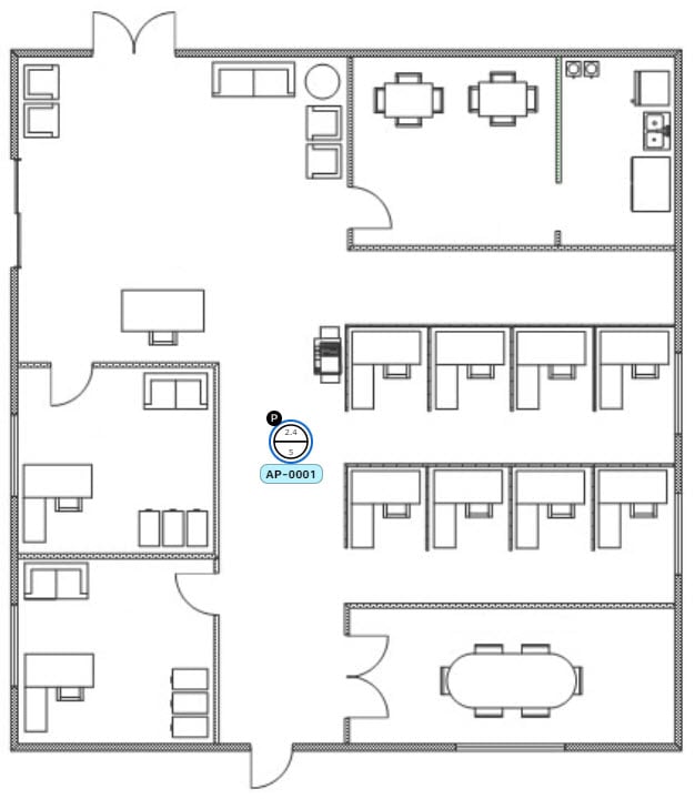
Define its x and y coordinates. Use this method if you have the exact coordinates of the AP and you want its position on the map to be as accurate as possible.
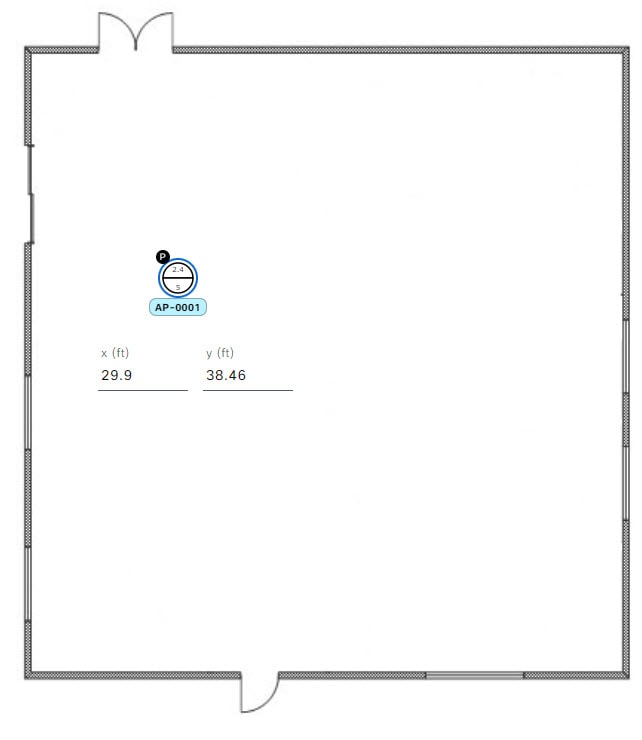
Triangulate it using 3 points. Use this method if you have large open space with only a few points from which to measure the distance to the AP. For example, you might measure from the AP to each corner of the room.
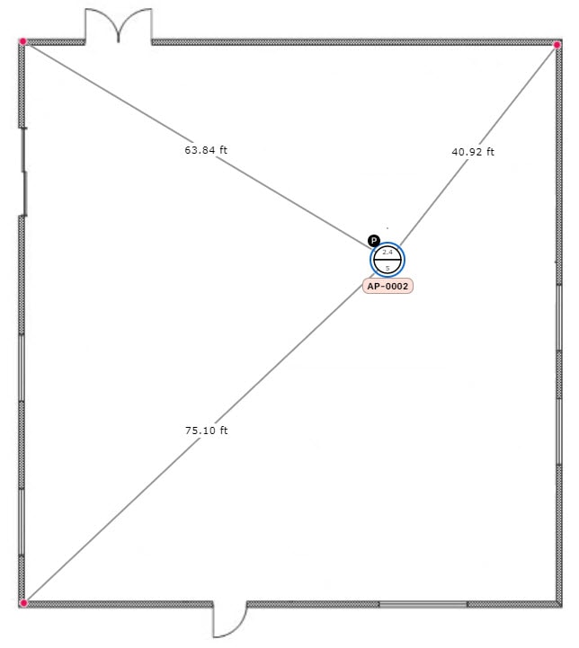
Intersect it based on its distance from two walls. Use this method if the AP is located in a space where you have two walls that intersect, even if they aren't perpendicular to one another.
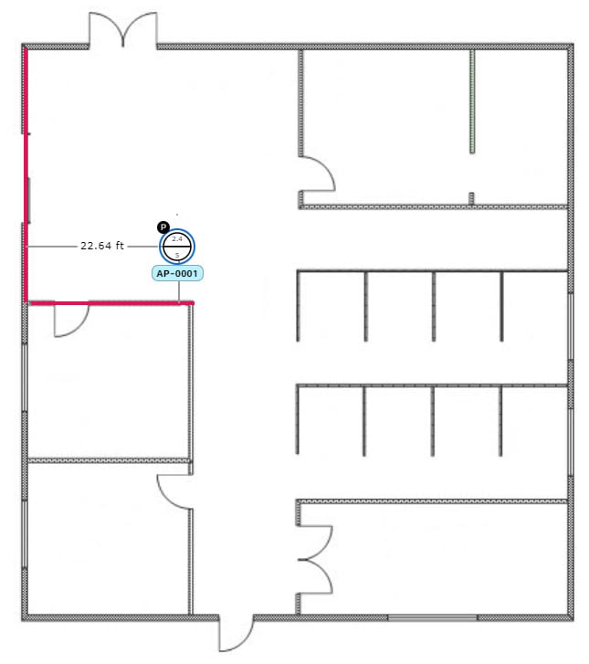
For all but the first method (manual positioning), you must have your measurements on hand, and make sure the unit of measure is specified correctly in the Global Map Properties settings. For information, see 2D map view options.
|
Step 1 |
From the main menu, choose . |
||
|
Step 2 |
From the left hierarchy tree, select a floor. |
||
|
Step 3 |
In the map toolbar, click . By default, the Devices and Access Points toggle buttons are chosen. |
||
|
Step 4 |
From the left pane of the map, in the Unpositioned area, click an AP. 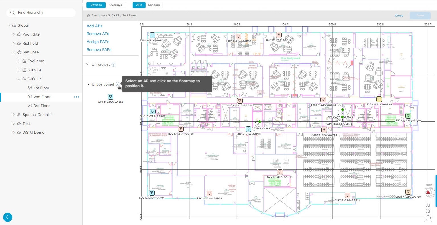
|
||
|
Step 5 |
To position the AP, use one of these methods:
|
||
|
Step 6 |
In the map toolbar, click Save.
|
If your network uses Cisco ISE for user authentication, you can configure Catalyst Center for Cisco ISE integration. This enables you to see more information about wired clients, such as the username and operating system.
Cisco ISE configuration is centralized within NCP (Network Control Platform), which enables you to configure Cisco ISE at one GUI location. Here's the workflow for configuring Cisco ISE:
From the main menu, choose , and enter the Cisco ISE server details.
After the Cisco ISE server is successfully added, NCP establishes a connection with NDP (Network Data Platform) and sends the details of the pxGrid nodes, keystore, and truststore files.
NDP uses the configuration received from NCP to establish a pxGrid session.
NCP automatically detects pxGrid node failovers, persona moves, and communicates it to NDP.
If there are ISE deployment changes, NDP starts a new pxGrid session with a new pxGrid ACTIVE node.
Catalyst Center uses AAA servers for user authentication and Cisco ISE for both user authentication and access control. Use this procedure to configure AAA servers, including Cisco ISE.
If you are using Cisco ISE to perform both policy and AAA functions, make sure that Catalyst Center and Cisco ISE are integrated.
If you are using another product (not Cisco ISE) to perform AAA functions, make sure to do these task:
Register Catalyst Center with the AAA server, including defining the shared secret on both the AAA server and Catalyst Center.
Define an attribute name for Catalyst Center on the AAA server.
For a Catalyst Center multihost cluster configuration, define all individual host IP addresses and the virtual IP address for the multihost cluster on the AAA server.
Before you configure Cisco ISE, confirm that:
You have deployed Cisco ISE on your network. For information on supported Cisco ISE versions, see the Cisco Catalyst Center Compatibility Matrix. For information on installing Cisco ISE, see the Cisco Identity Services Engine Install and Upgrade guides.
If you have a standalone Cisco ISE deployment, you must integrate Catalyst Center with the Cisco ISE node and enable the pxGrid service and External RESTful Services (ERS) on that node.
If you have a distributed Cisco ISE deployment:
You must integrate Catalyst Center with the primary policy administration node (PAN), and enable ERS on the PAN.
Note |
We recommend that you use ERS through the PAN. However, for backup, you can enable ERS on the Policy Service Nodes (PSNs). |
You must enable the pxGrid service on one of the Cisco ISE nodes within the distributed deployment. Although you can decide to do so, you do not have to enable pxGrid on the PAN. You can enable pxGrid on any Cisco ISE node in your distributed deployment.
The PSNs that you configure in Cisco ISE to handle TrustSec or SD Access content and Protected Access Credentials (PACs) must also be defined in . For more information, see the Cisco Identity Services Engine Administrator Guide.
You must enable communication between Catalyst Center and Cisco ISE on these ports: 443, 5222, 8910, and 9060.
The Cisco ISE host on which pxGrid is enabled must be reachable from Catalyst Center on the IP address of the Cisco ISE eth0 interface.
The Cisco ISE node can reach the fabric underlay network via the appliance's NIC.
The Cisco ISE admin node certificate must contain the Cisco ISE IP address or the fully qualified domain name (FQDN) in either the certificate subject name or the Subject Alternative Name (SAN).
The Catalyst Center system certificate must list both the Catalyst Center appliance IP address and FQDN in the SAN field.
|
Step 1 |
From the main menu, choose . |
||||
|
Step 2 |
From the Add drop-down list, select AAA or ISE. |
||||
|
Step 3 |
To configure the primary AAA server, enter this information:
|
||||
|
Step 4 |
To configure a Cisco ISE server, enter these details:
|
||||
|
Step 5 |
Click Advanced Settings and configure the settings:
|
||||
|
Step 6 |
Click Add. |
||||
|
Step 7 |
To add a secondary server, repeat the preceding steps. |
||||
|
Step 8 |
To view the Cisco ISE integration status of a device:
|
With Catalyst Center, you can configure global network settings when devices are assigned to a specific site. Telemetry polls network devices and collects telemetry data according to the settings in the SNMP server, syslog server, NetFlow Collector, or wired client.
Create a site and assign a device to the site. See Create, edit, and delete a site.
|
Step 1 |
From the main menu, choose Design > Network Settings > Telemetry. |
||
|
Step 2 |
In the SNMP Traps area, do one of these tasks:
|
||
|
Step 3 |
In the Syslogs area, do one of these tasks:
|
||
|
Step 4 |
In the Application Visibility area, check the Enable by default on wired access devices check box to enable Application Telemetry and Controller-Based Application Recognition (CBAR) by default upon the network device site assignment. Do one of these tasks:
|
||
|
Step 5 |
In the Wired Endpoint Data Collection area, click the Enable Catalyst Center Wired Endpoint Data Collection At This Site radio button to turn on IP Device Tracking (IPDT) on the access devices of the site. If you don't want to enable IPDT for the site, click the Disable Catalyst Center Wired Endpoint Data Collection At This Site radio button (the default). After enabling IPDT, clients connected to access ports are visible in Catalyst Center. Clients connected to trunk ports and port channels aren’t visible in Catalyst Center.
|
||
|
Step 6 |
In the Wireless Controller, Access Point and Wireless Clients Health area, check the Enable Wireless Telemetry check box to monitor the health of the wireless controllers, APs, and wireless clients in your network. During the Device Controllability workflow, enabling Wireless Telemetry activates telemetry data collection and provisions telemetry commands to wireless configurations. When you disable this feature, telemetry setup stops, and monitoring capabilities are lost. For more information, see Device controllability in Cisco Catalyst Center Administrator Guide. |
||
|
Step 7 |
Click Save. |
Use this procedure to enable the Cisco AI Analytics features to export network event data from network devices and inventory, site hierarchy, and topology data to the Cisco AI Cloud.
Make sure that you have the Advantage software license for Catalyst Center. The AI Network Analytics application is part of the Advantage software license.
Make sure that the latest version of the AI Network Analytics application is installed. See the "Download and Install Packages and Updates" topic in the Cisco Catalyst Center Administrator Guide.
Make sure that your network or HTTP proxy is configured to allow outbound HTTPS (TCP 443) access to these cloud hosts:
api.use1.prd.kairos.ciscolabs.com (US East Region)
api.euc1.prd.kairos.ciscolabs.com (EU Central Region)
|
Step 1 |
From the main menu, choose . |
|
Step 2 |
Scroll down to External Services and select Cisco AI Analytics. 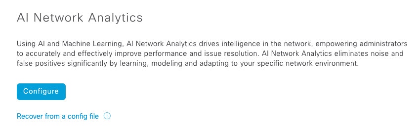
|
|
Step 3 |
Do one of these tasks:
|
|
Step 4 |
In the Success dialog box, click Okay. |
|
Step 5 |
(Recommended) In the AI Network Analytics window, click Download Configuration file. |
To disable Cisco AI Network Analytics data collection, you must disable the AI Network Analytics feature:
|
Step 1 |
From the main menu, choose . |
|
Step 2 |
Scroll down to External Services and choose Cisco AI Analytics. |
|
Step 3 |
In the AI Network Analytics area, click the Enable AI Network Analytics toggle button so that it’s unchecked ( |
|
Step 4 |
Click Update. |
|
Step 5 |
To delete your network data from the Cisco AI Network Analytics cloud, contact the Cisco Technical Response Center (TAC) and open a support request. |
|
Step 6 |
If you have misplaced your previous configuration, click Download configuration file. |
Machine Reasoning knowledge packs are step-by-step workflows that are used by the Machine Reasoning Engine (MRE) to identify security issues and improve automated root cause analysis. These knowledge packs are continuously updated as more information is received. The Machine Reasoning Knowledge Base is a repository of these knowledge packs (workflows). To have access to the latest knowledge packs, you can either configure Catalyst Center to automatically update the Machine Reasoning Knowledge Base daily, or you can do a manual update.
|
Step 1 |
From the main menu, choose . |
|
Step 2 |
Scroll down to External Services and select Machine Reasoning Knowledge Base.
When there’s a new update to the Machine Reasoning Knowledge Base, the AVAILABLE UPDATE area is displayed in the Machine Reasoning Knowledge Base window, which provides the Version and Details about the update.
|
|
Step 3 |
(Recommended) Check the AUTO UPDATE check box to automatically update the Machine Reasoning Knowledge Base. You can perform an automatic update only if Catalyst Center is successfully connected to the Machine Reasoning Engine in the cloud. |
|
Step 4 |
To manually update the Machine Reasoning Knowledge Base in Catalyst Center, do one of these tasks:
|
|
Step 5 |
Check the CISCO CX CLOUD SERVICE FOR NETWORK BUG IDENTIFIER AND SECURITY ADVISORY check box to enable Cisco CX Cloud connection with network bug identifier and security advisory. |
|
Step 6 |
In the Security Advisories Settings area click the RECURRING SCAN toggle button to enable or disable the weekly recurring scan. |
|
Step 7 |
Click the CISCO CX CLOUD toggle button to enable or disable the Cisco CX cloud. |
You can view the Catalyst Center GUI windows in English (the default), Chinese, Japanese, or Korean.
To change the default language:
|
Step 1 |
In your browser, change the locale to one of the supported languages: Chinese, Japanese, or Korean.
|
|
Step 2 |
Log in to Catalyst Center. The GUI shows in the selected language. |
 .
.
 ) in the
  )
)
 )
)
 )
)
 next to the parent site in the left pane, and select
  ) for the device.
 icon in the top-right corner, and then select
  icon in the top-right corner, and then select
  Feedback