Transport Slice Provisioning

This section explains the following topics:

Overview

Objective

Simplify transport service provisioning by focusing on the service's SLA intents (the "what" instead of the "how"). This implies a service-oriented view, leveraging the concepts of software-defined networking (SDN).

Challenge

Service providers face ever-growing demands from end users for highly customized, flexible network services with very different, sometimes contradictory, service level requirements: support for highly mobile smart cars, ultralow-latency AR and mobile gaming applications, secure machine-to-machine communication in logistics and manufacturing, and so on. Modern software-defined network (SDN) traffic engineering technologists have responded with a host of innovative protocols and features that offer many ways to engineer network traffic to meet these special needs. Crosswork support for these approaches, such as SR-TE services, Tree-SID, and Local Congestion Mitigation, are featured elsewhere in this Guide.

The advent of 5G mobile networking has accelerated this trend, resulting in a new approach to network architecture: network slicing. This still-emerging standard enables network engineers to slice the 5G network's bandwidth into tranches that prioritize some services over others instead of treating it as a single, monolithic network. The network engineer can design each network slice around the needs and intents of its users, allocating speed, latency, throughput, and other resources to each slice as required. CNC delivers a rich and customizable tool set to make deploying these slices easier. When combined with Service Health, it provides the added ability to easily monitor the health of these services. The provider organization can then offer the slice itself as a service, helping to broaden the range of service offerings.

But how to make these services easy to provision? The design and coding of the sophisticated traffic engineering services that underlie network slicing require the skills of experienced network architects and deep knowledge of each provider's existing network infrastructure. Without automation that allows line operators to instantiate the designed slices quickly and easily, network slices might remain a type of custom configuration, achievable only for a small set of important users, instead of scalable commodity providers that can monetize.

This is an evolving standard. Currently, the Crosswork solution only addresses the Transport-level Network Slice Management Functions (NSMF).

Solution

Crosswork Network Controller offers direct support for network slicing at the OSI transport layer. Using this solution, network engineering experts can design slices around customer intents and add them to a catalog. Network line operators can then pick the slice intent that best meets the customer's needs, specify the slice endpoints, and (where needed) set any custom constraints or options built into the chosen slice.

This is Cisco's initial offering in the network slicing arena, chosen because of our company's strengths at the transport layer. Currently, the Crosswork solution provides a large catalog of slice template examples and extensive customization for each template. This document offers a scenario that you can follow to create and (optionally) monitor a network slice.

How does transport slicing work?

It's important at the outset to understand the difference between 5G network slicing and generalized transport slicing. When operational, a 5G network slice is an end-to-end solution crossing multiple sub-domains. The 5G network authority 3rd Generation Partnership Project (3GPP) refers to each end-to-end network slice operating on the network as the Network Slice Instance (NSI). Each NSI is a unique entity, provisioned in the network with a set of Service Level Requirements chosen from a set of pre-created Network Slice Templates (NST).

All NSIs must be orchestrated by a controller called the Network Slice Management Function (NSFM). The NSMF, in turn, communicates with sub-domain controllers, referred to as Network Slice Subnet Management Functions (NSSMF). Each NSSMF provisions the corresponding domain-specific slice instance across its sub-domain boundaries (called a Network Slice Subnet Instance or NSSI). For the Transport domain, the IETF has defined the NSSI as an “IETF Network Slice” to differentiate slices in the transport domain from slices bridging other domains. The space occupied by transport slicing in this hierarchy is shown in the illustration below, where the CNC solution will provide the NSSMF functionality for the Transport domain. It is important to highlight that Cisco's Transport Slicing solution can be used independently from 5G use cases, as it's a generic solution for implementing any transport service based on intents.

Figure 1. Defining transport slicing scope
Defining Transport Slicing Scope

Simplification and ease of use are key principles in transport slicing. The operator wants to start very simply, by requesting from a controller a service based on a desired service intent or outcome (such as supplying low latency to an AR application). They then want the controller to build the service.

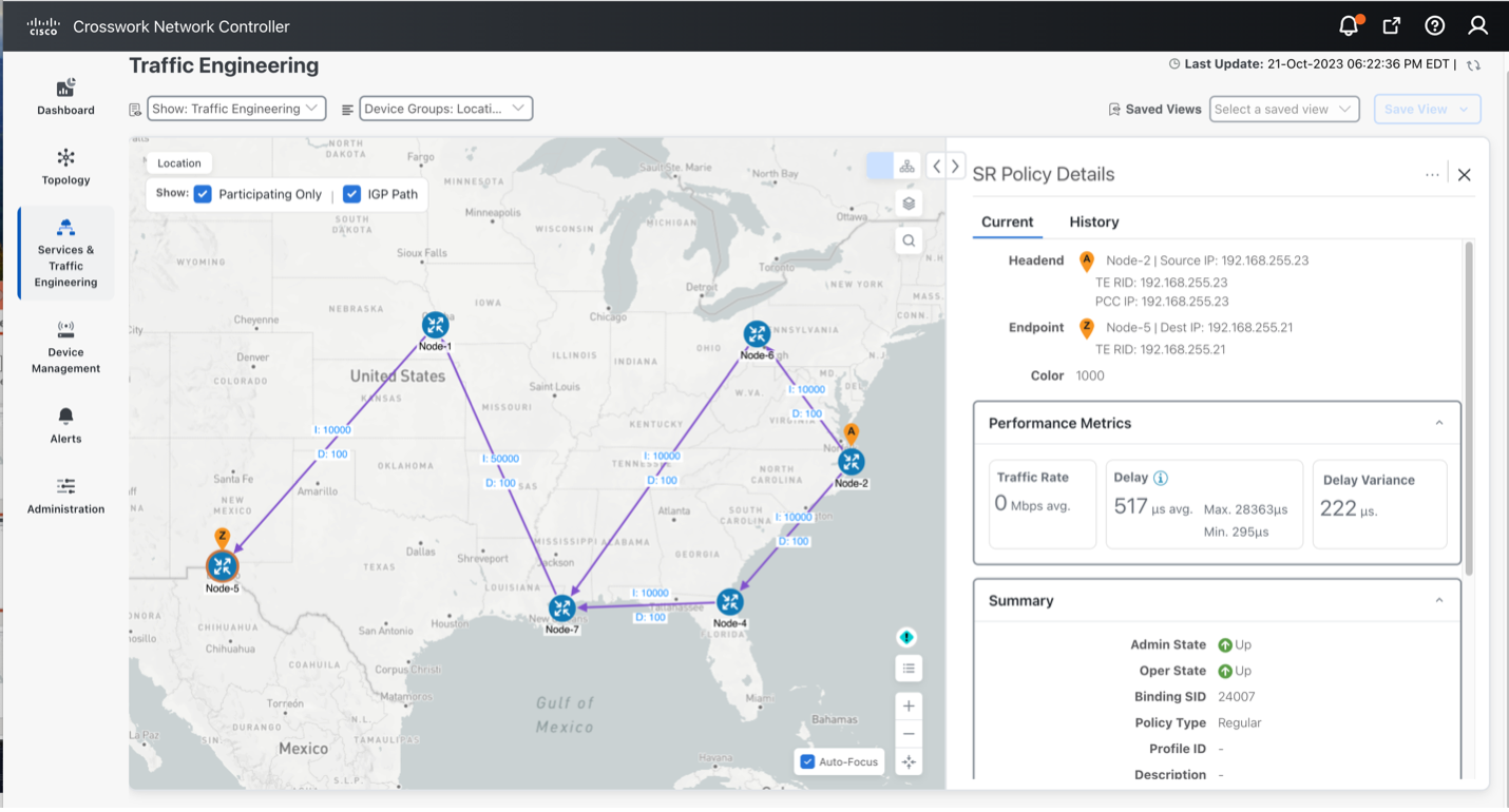
The controller must also monitor the built service to ensure it honors the operator's intent. Above all, the operator wants to avoid exposure to the many configuration parameters required to deploy the service at the device layer. Realizing that vision involves the creation of intent-based modularity for value-added transport services supporting the slice, using well-abstracted and declarative service-layer APIs. These service APIs must be maintained and exposed by a controller that can act in a declarative and outcome-based way, as shown in the following figure.

Figure 2. Abstracting service intents and outcomes
Abstracting Service Intents and Outcomes

Monitoring the slice's fidelity to the intent involves a Service Level Agreement (SLA) between the customer and the slice provider. To ensure that this SLA effectively reflects the slice's intended purpose and includes specific, actionable terms, it can be further categorized as either a Service Level Objective (SLO) or a Service Level Expectation (SLE):

  • Service Level Objective (SLO): A desired and achievable target value or range of values for the measurements obtained from observing a Service Level Indicator (SLI). For instance, an SLO may be stated as "SLI <= target" or "lower bound <= SLI <= upper bound".

  • Service Level Expectation (SLE): The expression of an unmeasurable service-related request that a customer makes of the provider. An SLE differs from an SLO as the customer may have limited means of ascertaining whether the SLE is being fulfilled but still enters into an agreement with the provider for a service that meets the expectation (refer to the sample SLE table below).

Table 1. Sample service level expectations

SLE

Description

Encrypted Link Services Traffic must transit encrypted links only.
Disjoint Path Services The network has multiple forwarding planes with no common nodes or links.
High speed links only Traffic must transit high-speed links only. Links offering speeds greater than or equal to 100Gbps are typical for "elephant flows".
Lowest Latency Always take the lowest latency path. No SLO would be specified in this case.
Regional Avoidance Do not use nodes or links in specific regions or countries.
Trusted Nodes Only use trusted nodes ("trusted" meaning verified and not in the common carrier space).
L4-L7 Services Redirect to “in-line” L4-L7 service on traffic (typically used for security services).
Reliable Links Use only transit links that have optical protection and L1 diversity.
“Circuit-Style” Services Provide L1 circuit-like connectivity.
Gaming Services Use network segments optimized for network gamers (low latency, high bandwidth)
Connected Car Use network segments optimized for network-connected cars (low latency, close proximity)
Cloud Provider-Specific Connect me to the secure “walled garden” for a cloud provider (such as AWS or Azure).

The SLA, therefore, sets key goals and measures to be applied for a given connectivity construct between a sending endpoint and the set of receiving endpoints. It also describes the extent to which divergence from individual SLOs and SLEs can be tolerated and the specific consequences for violating these SLOs and SLEs.

What makes up a Cisco transport slice?

To build and deploy these highly abstract intents, Crosswork Network Controller must translate them into actual device configurations. Governing bodies like the IETF and 3GPP leave these decisions to vendors. Cisco can leverage a complete toolkit built over many years of innovation, as shown in the following figure.

Figure 3. Cisco's transport slicing toolkit
Cisco's Transport Slicing Toolkit

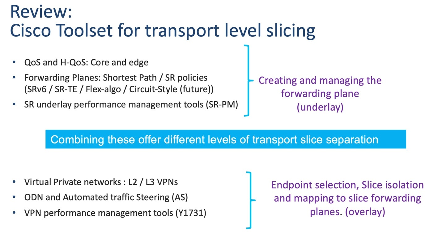
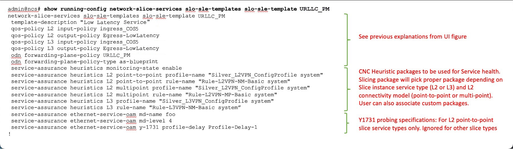
For a Cisco Transport Slice Instance, we categorize the features in the preceding illustration as follows: Service Assurance, Path Forwarding, QOS (PHB), and BGP-based EVPN. The configurations in these categories support the slice instance, as shown in the illustration below.

Figure 4. Cisco's transport slice instance
Cisco's Transport Slice Instance

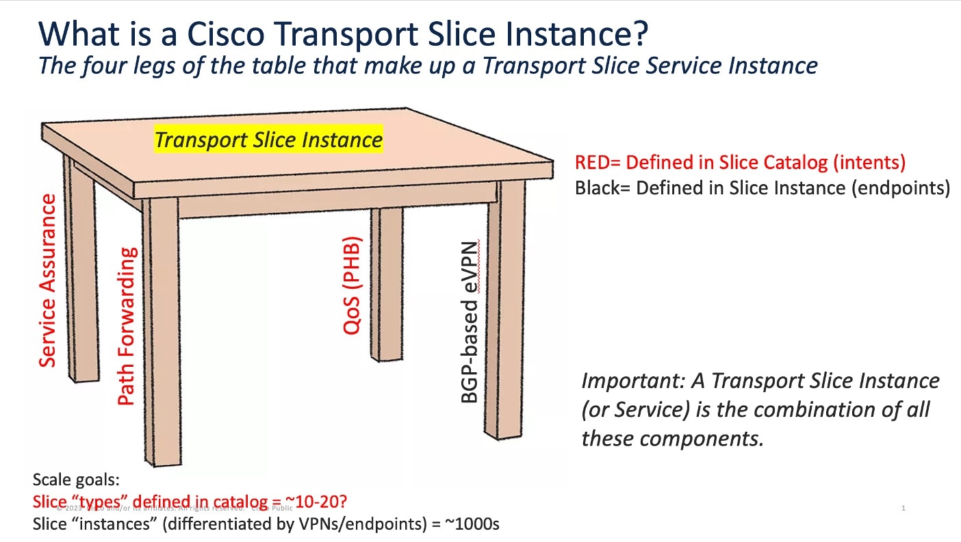
The first three of these features (shown in red) are defined in the slice template catalog (this catalog is equivalent to what 3GPP calls the NSST). The slice catalog contains templates, each defined once by a slice designer. Slice templates are just blueprints and are not instantiated in the network in any way. Slice instances are the instantiated services after they are deployed in the network. The end-user doesn’t need to know the details of what is inside the templates, just the overall intent (or SLA) for each slice template. The slice template catalog is thus a catalog of slice intents.

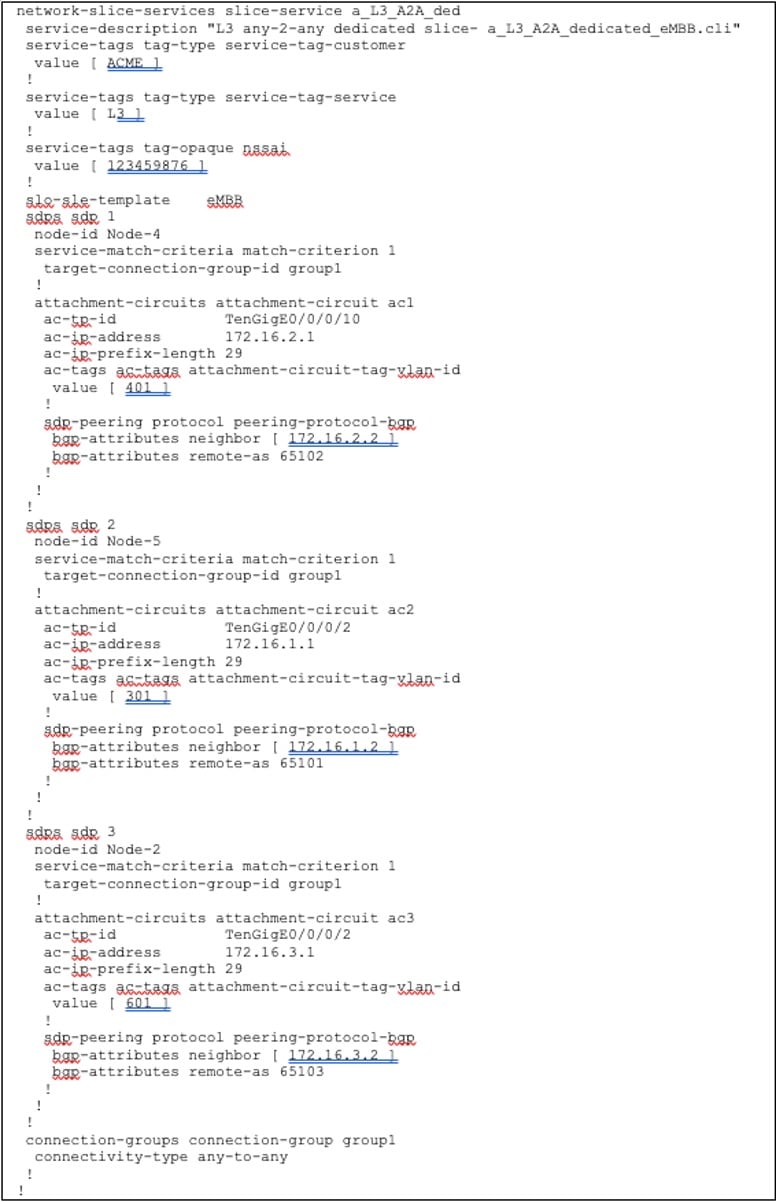
The fourth category – BGP-based VPNs – that make up a Cisco Transport Slice Instance is the selection of endpoints and service types (L2 or L3 forwarding). Operators define these when deploying the Cisco Transport Slice Instance.

The benefit of this approach is to fully abstract the underlying configuration details of the various machinery components required to realize a Cisco Transport Slice Instance (aka the IETF Network Slice, or, in 3GPP parlance, the Network Subnet Slice Instance or NSSI).

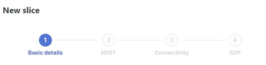
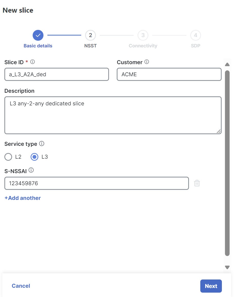
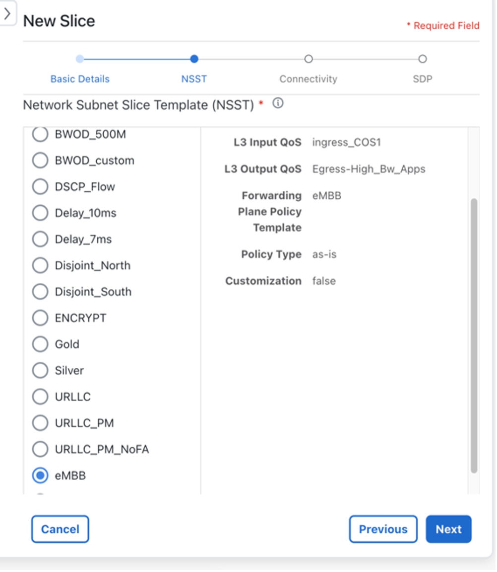
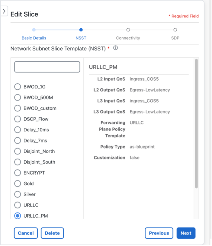
To deploy a new slice instance, the operator executes the following steps:

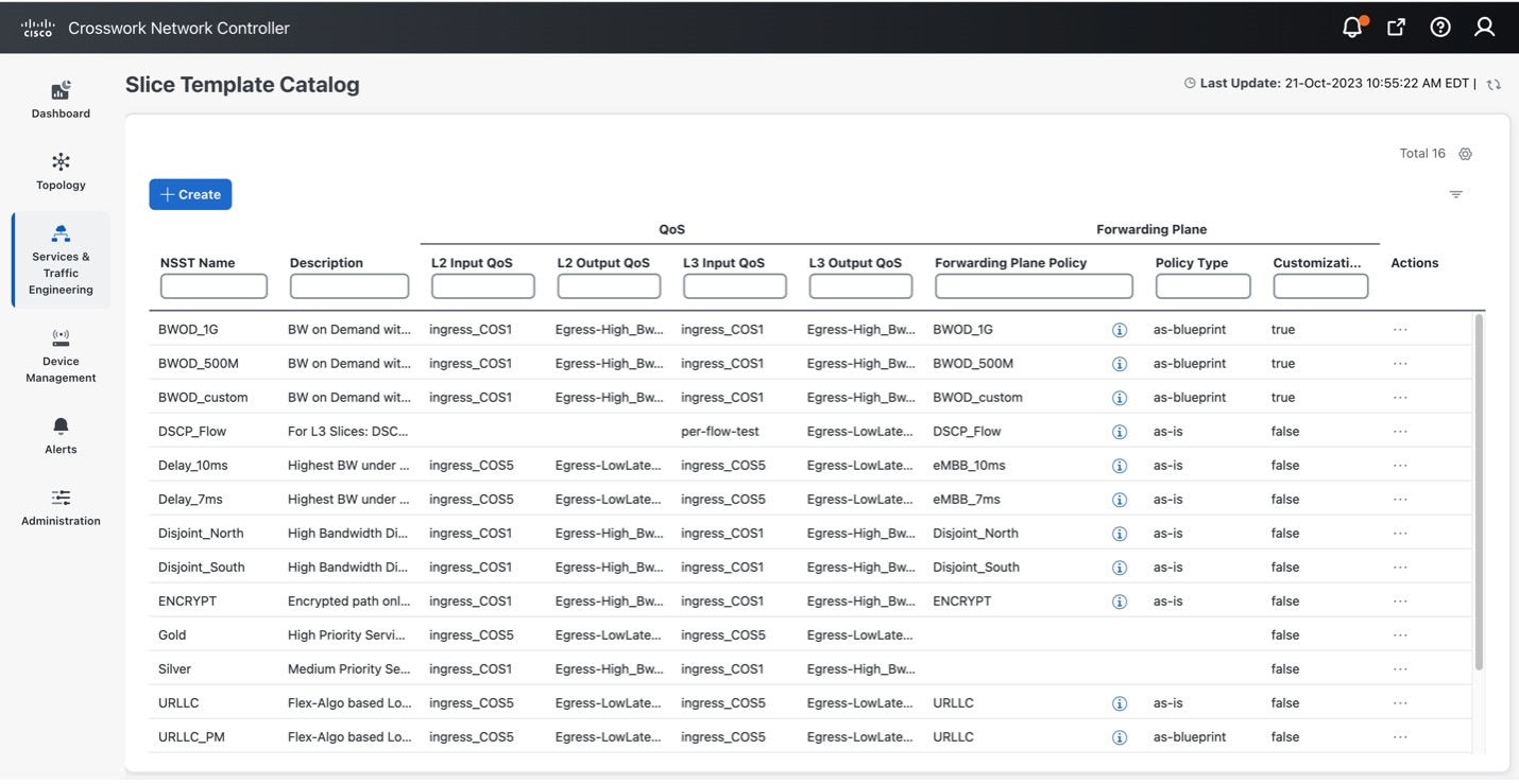
  1. Select a slice intent from the available Templates in the Slice Catalog.

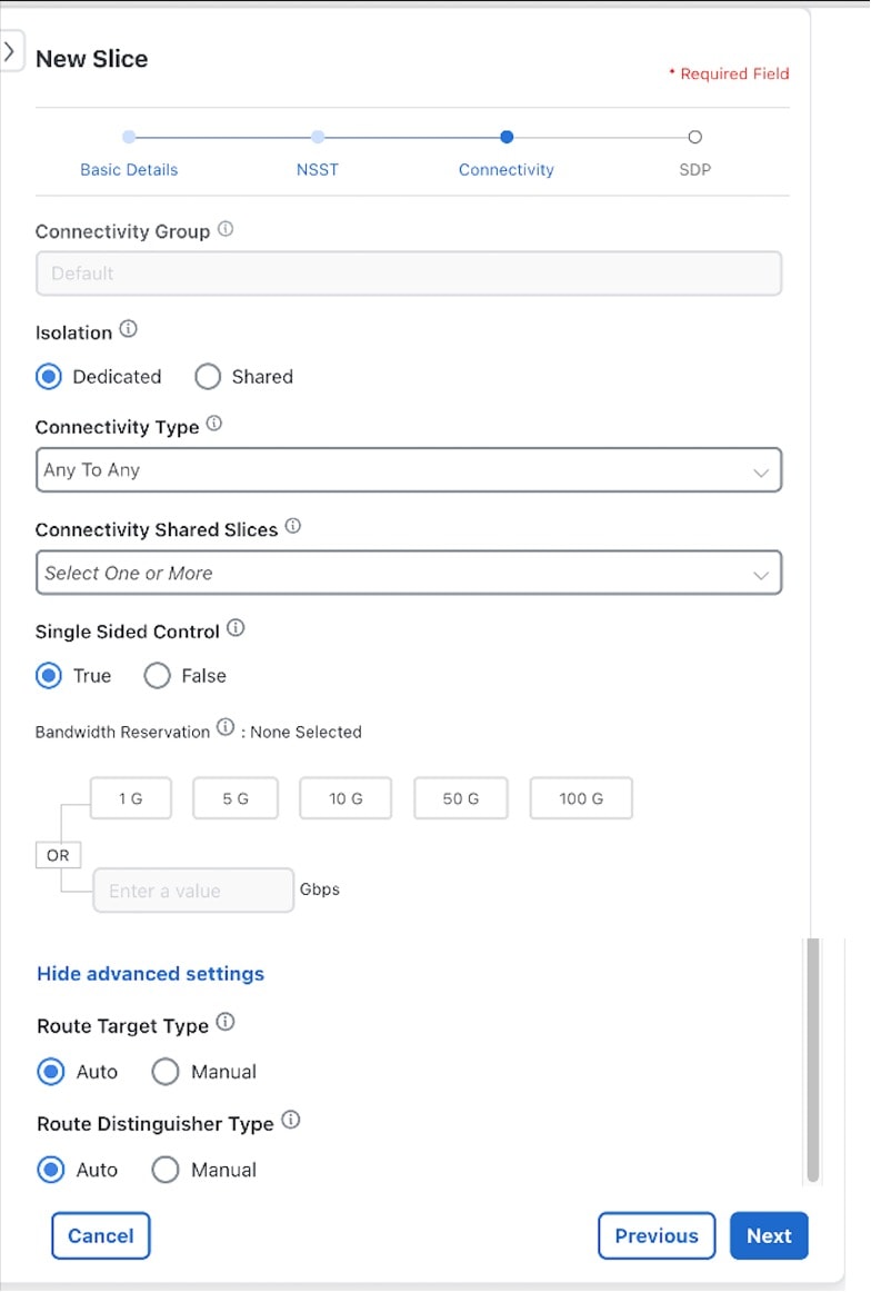
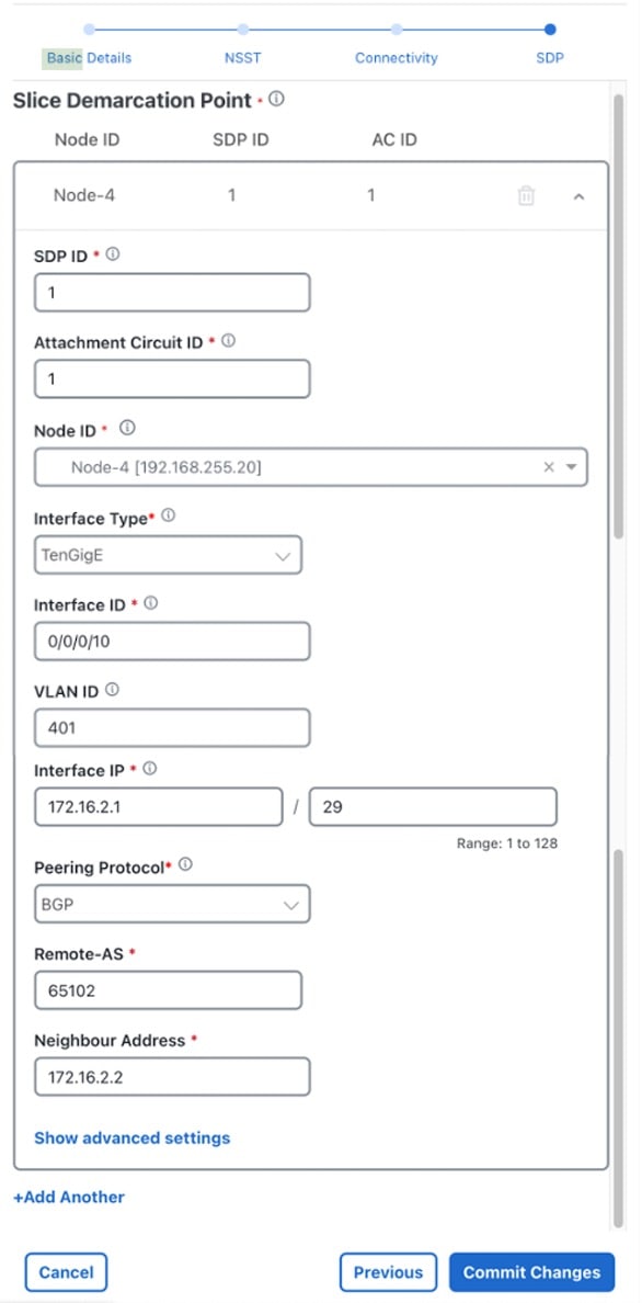
  2. Select slice endpoints and connectivity details, which drive the VPN configuration. Once committed, Crosswork Network Controller will then provision:

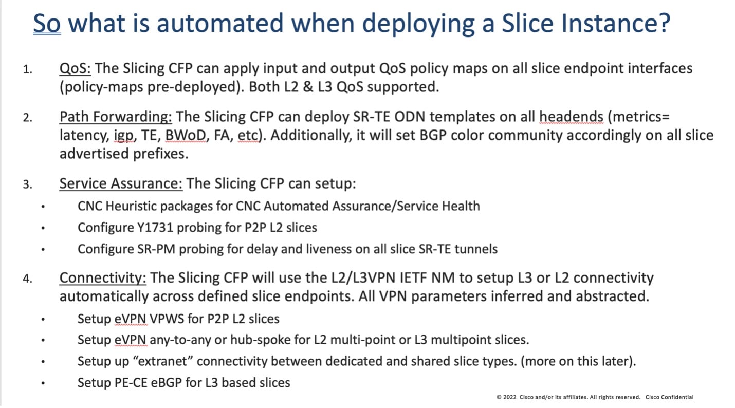
    • The forwarding plane policy details which drive the segment routing traffic engineering (SR-TE) configurations and BGP prefix coloring for ODN/AS.

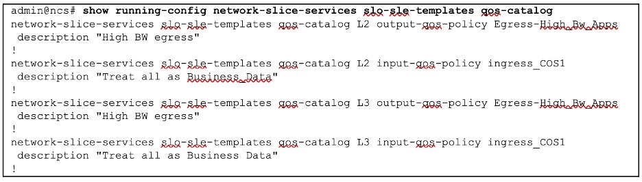
    • The QoS profile details, which drive the ingress marking (for PHB treatment) and the egress scheduling.

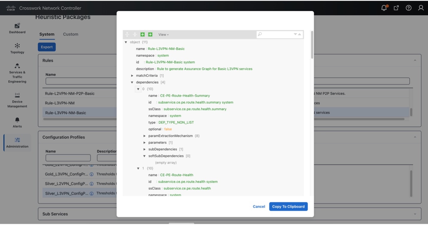
    • The SLA details, which will drive the needed Service Assurance configurations.

    • The BGP based VPN connectivity requirements to provide endpoint connectivity.

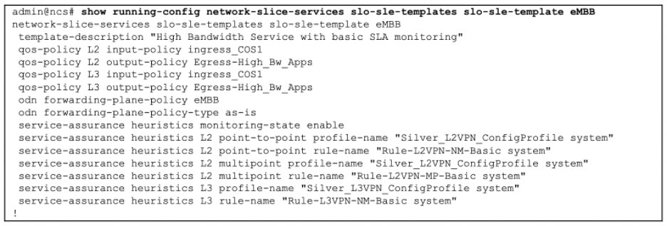
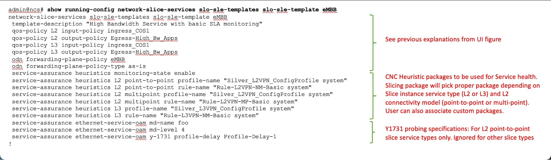
The following illustration provides more detail on the parts of the slice template that automate slice instantiation.

Figure 5. What is automated when deploying a slice instance
What is automated when deploying a slice instance

Transport slice high level workflow

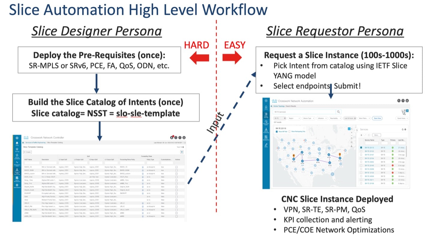
Transport slicing in Crosswork Network Controller is designed around two main user personas:

Slice Designer: The designer understands the service requirements the provider organization wants to offer customers and is familiar with the provider network's underlying capabilities. This person has authorization to do one-time setup operations within the network and has a networking engineering background. They will set up the needed network prerequisites and build the slice template catalog, which lists available slice service offerings for network operators.

Slice Requestor: The requestor requests new slice instances using the intent-based and simplified CNC user interface. They pick their desired slice type from the pre-built slice catalog, select their endpoints and transport options, and then click submit.

Cisco's objective in Crosswork Network Controller transport slice solution is to make the user experience as simple as possible for the Requestor. This is the only slice deployment operation driving network service provisioning, and as it must be done constantly for a large SP network, it is a major contributor to provider OPEX. The slice template catalog creation is done once by highly skilled designer personnel. While the design step is not automated, this approach leverages those skilled resources in a way that maximizes their value to the provider organization at a scale that cannot be realized if the designer must instantiate every slice by hand. The catalog creation requires a good understanding of the network and its capabilities, and requires pre-requisite configurations as shown in the figure below. Slice designers must be familiar with all the pre-requisite configuration types listed in the illustration for this approach to work.

Figure 6. Role of the slice designer and requestor
Role of the Slice Designer and Requestor

Scenario: Implement an any-to-any L3 eMBB slice

In this scenario, you require a transport slice with Layer3 any-to-any connectivity across three endpoints, using the intent defined in the catalog for Mobile Broadband (eMBB). The eMBB intent will provide the highest bandwidth available path (including proper QoS marking/scheduling treatment), and some basic service assurance capabilities such as endpoint interface status and PE-CE route health. The eMBB intent will also enable you to specify:

  • The highest bandwidth available path.

  • Some basic service assurance capabilities.

  • eBGP peer routing connectivity details to CE devices.

Assumptions and prerequisites

This scenario assumes the network has already built the required network capabilities for this intent. However, they will be briefly reviewed here for this scenario. For more detailed explanations, see the Cisco Transport Slice Automation Design Guide.

Slice service package prerequisites

The NSO slice services package uses a few optional prerequisites that need to be bootstrapped into NSO. The prerequisites required depend on the types of slices and intents required.

First, suppose you plan on using any “as-blueprint” forwarding-plane-policy-types in your template catalog. In that case, you must create an NSO sr-color resource pool so that the slicing service can dynamically assign colors to create ODN policies. This pool should then be referenced by the slicing service.

Second, if creating point-to-point L2 slice service types, the route-policy map assigned to the BGP session for the route reflector must be identified to the slicing package. This policy map will be modified by the slicing package with new policies as needed for L2 services, which is a standard approach for VPWS.

In this scenario, these items are not required since you are using neither of these functions:

resource-pools id-pool sr-color-pool
range start 1000
range end 2000
!
network-slice-services cfp-configurations color-pool-name sr-color-pool
network-slice-services global-settings parent-rr-route-policy SET_COLOR_EVPN_VPWS
!

Path forwarding prerequisites

The following settings have been preconfigured with the NSO T-SDN SR-TE CFP for the eMBB ODN path-forwarding intent with these properties:

  • Use Color 100 to identify the intent.

  • PCE is responsible for dynamic path computation

  • The dynamic path computation will be based on the IGP metric.

On NSO, this set of properties will look like the below example. At this stage, the ODN policy has not been pushed to the devices.

admin@ncs# show running-config cisco-sr-te-cfp:sr-te odn odn-template eMBB
cisco-sr-te-cfp:sr-te odn odn-templatee eMBB
 color 100
 dynamic pce
 dynamic metric-type igp
!

QoS prerequisites

As described, you (the Slice Designer) should have a good understanding of the network's settings and device capabilities. You should have a well-designed and implemented QoS design throughout your network. For instance, for QoS treatment for high bandwidth business services, you have chosen to deploy these services with the network's existing "Class of Service 1" traffic policy (called "ingress_COS1").

The details of this policy are again provider-specific, but in this example, the policy will not examine or modify the ingress traffic's IP DSCP setting but mark all the traffic with an MPLS experimental bit (EXP) of 1 so that downstream core scheduling can provide the proper BW treatment. On egress from the provider network, you have chosen a policy called “Egress-High_BW-Apps,” which will assign 50% of the bandwidth to Class of Service 1 (COS1) marked traffic.

It is assumed these QoS policies are already deployed on all edge PE devices (they still need to be added to the customer-facing interfaces but have been built out and ready for use). However, you still need to identify that these QoS policies are available in the Slice Template catalog for Slice services. You will need to provide that mapping and identify which policies are available for either Layer 2 or Layer 3 slice services or both. Since QoS policies can be tailored specifically to Layer 3 or Layer 2 traffic (for example, matching on L3 DSCP vs L2 ToS bits), the system allows you to specify the usage. In the case of the example above, since all traffic is marked with EXP=1 regardless of DSCP or ToS, these policies apply to L2 or L3 services.

Figure 7. QoS prerequisites

QoS Prerequisites

Slice service assurance settings

In this scenario, you only have basic service assurance requirements, which are based on passive state monitoring (no active probing). You will be using Crosswork Network Controller's Service Health capability and the Crosswork Network Controller system’s pre-built heuristic packages (ConfigProfiles and Rules) which define the objects to be monitored. In the scenario, you want to monitor basic device health and PE-CE route health, which are included in the basic system package. When you build the slice catalog, you can define which packages to use for L2 point-to-point, L2 multipoint, and/or L3 services.

The scenario above requires L3 services, but when you create your catalog for the eMBB intent (next step), you also need to consider future slice instances for eMBB services that are L2 service types. Thus, you can include all these pre-built system heuristic packages in the catalog entry for eMBB. Since these are all pre-built system packages, no prerequisite configurations are required. The system heuristic packages can be viewed via the CNC UI by selecting Administration> Heuristic Packages (see figure below).

Table 2. Heuristic profile and rule names for eMBB

System heuristic profile and rule names used for eMBB

Usage

Silver_L3PN_ConfigProfile system

Rule-L3VPN-NM-Basic system

L3 profile-name

L3 rule-name

Silver_L2PN_ConfigProfile system

Rule-L2VPN-MP-Basic system

L2 multipoint profile-name

L2 multipoint rule-name

Silver_L2PN_ConfigProfile system

Rule-L2VPN-NM-Basic system

L2 point-to-point profile-name

L2 point-to-point rule-name

Figure 8. Slice service assurance settings

Slice Service Assurance Settings

Step 1 Create a slice template catalog entry

You will now build out the slice catalog entry for eMBB intent-based slice services. This operation is done once, using the above components as input, and can cover both L2 and L3 slice instance requests. Once complete, you can move to deploy the slice service instance for this scenario, and this entry will now be available for future slice instances requiring eMBB intent services (for example, all of the above prerequisite steps will not be required).

This step, performed by the Slice Designer, builds a slice catalog of intents or slice types that will be referred to when creating the actual slice instance. This catalog (along with the slice instances themselves) can be built in multiple ways:

  • Using the Crosswork Network Controller UI

  • Using the Crosswork Network Controller or NSO Slicing API

  • Using the NSO CLI, including load merge from a text file

This scenario has a Service Assurance option that can only be created using NSO CLI or Crosswork Network Controller API. It will be shown in the Step 2. Add service assurance into the slice template catalog using the NSO CLI.

Figure 9. Slice template catalog prerequisites

Slice Template Catalog Prerequisites

To create a slice template catalog entry using the Crosswork Network Controller UI, do the following:

Procedure


Step 1

From the main menu, choose Services & Traffic Engineering > Slice Template Catalog.

The Slice Template Catalog screen appears.

Note

 
For the purpose of this scenario, the templates that appear in the image below have already been created on NSO.
Figure 10. Slice template catalog

Slice Template Catalog

Step 2

Click + Create to create a new slice catalog entry. The New Slice Template screen appears.

Step 3

For Network Subnet Slice Template (NSST), type the new slice template name: eMBB. In addition, in the Description field, type a short description of the slice template’s intent: High Bandwidth Service.

Step 4

Assign the QoS ingress and egress policies. This depends on the slice instance Service Type (L2 or L3 policy), which you will define later when creating a new slice instance.

Note

 
For this scenario, the five fields at the bottom of the screen (L2 Input QoS, L2 Output QoS, L3 Input QoS, L3 Output QoS, Forwarding Plane Policy Template) have already been provisioned in NSO and automatically appear as an option in each list.

Note

 
You may also refer to the table built earlier and found under QoS in the prerequisites.
  • For L2 Input QoS, select ingress_COS1

  • For L2 Output QoS, select Egress-High_Bw_Apps

  • For L3 Input QoS, select ingress_COS1

  • For L3 Output QoS, select Egress-High_Bw_Apps

Step 5

For the Forwarding Plane Policy Template, select the ODN template policy created earlier (see prerequisites and assumptions section) that complements the forwarding plane intent. For this scenario, select eMBB.

Step 6

For Policy Type, determine if this template will be used as-is or as-blueprint. For this scenario, select as-is.

The as-is forwarding templates increase overall scalability as the SR-TE tunnels can be shared across multiple slice templates and instances. However, these ODN templates will not be dynamically modified by the slice package with additional functionality, including dynamic support for Performance Measurement or BWoD reservations.

Note


When as-blueprint is selected, determine if you also want to allow further per-slice instance customizations. These settings determine the SR-TE infrastructure re-use and the scale. Once as-blueprint is selected for Policy Type, the Allow Customizations check box will become available.

Step 7

Click Save.

Figure 11. New slice template
New Slice Template

Step 2 Add service assurance into the slice template catalog using the NSO CLI (optional)

If Service Assurance is required for the Slice instance, then the Slice Designer can add the necessary Service Assurance functionality into the Slice Template using NSO CLI or API. Below is a template in NSO CLI with Service Assurance parameters to be used for this scenario. It can be added directly into NSO CLI or with the API.

There are three service assurance sections in the template settings:

Procedure


Step 1

Reference pointers to Crosswork Network Controller Service Health Heuristic packages to be used and monitoring state. This monitoring state cannot be changed at the Slice instance level at this time; it is set universally for all slice instances referencing this Slice template. Various connectivity types (pt-2-pt or multi-point) can be chosen when setting up a slice instance, as well as different service types (L2 or L3). This means there are multiple heuristic package options available, and the system will choose the appropriate package based on the requirements of the slice instance.

Step 2

If the Slice Instance is an L2 service type with pt-2-pt connectivity, then Y1731 probe monitoring can be enabled. The required settings are shown in the example below. Slice SLA alarming, and alerting can be configured if the proper settings are selected in the L2 Heuristic package for Service Health.

Step 3

This scenario does not require Performance Measurement, so it is not included in the template below. However, if desired, it can be enabled in the template, and SR-PM will be dynamically configured on the SR-TE tunnel if the Slice Forwarding policy-type is set for as-blueprint. Slice SLA alarming, and alerting can be configured if the proper settings are selected in the Heuristic package for Service Health.

Figure 12. Slice template catalog
Slice Template Catalog

As previously highlighted, slice templates with service assurance parameters can only be created using the NSO CLI or Crosswork Network Controller/NSO API at this time. This also means these additional parameters will not be visible when viewing the slice template in Crosswork Network Controller UI.

Step 3 Create the transport slice instance

Once the slice type catalog has been created, we can now deploy the transport slice instance. The table below outlines the user data required to deploy this slice. The mandatory data consists of a series of string-data names (user-defined), selection of the service type (L2 or L3), catalog intent selection, and then defining the Service Demarcation Points (SDPs), which are the PE endpoints facing the customer. These PE endpoints will require IP information since this is an L3 slice, and optionally, since eBGP was desired for the PE-CE peering protocol, the CE eBGP information is required.

For this scenario, use the sample data below:

Table 3. Required parameter values

Parameter

User value

Mandatory

Notes

slice-service-name

a_L3_A2A_ded

Y

String. Maximum 17 characters. Must be unique.

description

“any string data”

N

Any string

customer

ACME

N

String meta data- user defined

service-tag

L3

Y

L2 or L3 forwarding

nssai

123459876

N

String meta data- could match 5G nssai assignment if provider desires

slo-sle-template

eMBB

Y

Selection from pre-built slice catalog

isolation

dedicated

N

The default is dedicated- the other option is shared

First SDP endpoint name

1

Y

String- unique within slice instance- At least one SDP must be created, the rest optional

Node-Name

Node-4

Y

PE Node-Name as defined in CNC topology

Attachment-circuit name

ac1

Y

String- unique within slice instance

Interface-ID

TenGigE0/0/0/10

Y

Customer facing PE Interface

VLAN ID

401

N

VLAN ID if using vlan sub-interfaces

Interface IP

172.16.2.1

Y

PE Interface IP address (since L3 service)

Interface IP Mask

29

Y

Interface prefix length (i.e. /29)

Peering protocol

BGP

N

PE-CE peering protocol (BGP or none)

BGP Neighbor ASN

65102

Y

Since bgp selected, peer ASN

BGP Neighbor Address

172.16.2.2

Y

Since bgp was selected, peer IP address

Second SDP endpoint name

2

N

Additional SDPs are optional, but in this scenario we have three endpoints

Node-Name

Node-5

PE Node-Name as defined in CNC topology

Attachment-circuit name

Ac2

String- unique within slice instance

Interface-ID

TenGigE0/0/0/2

Customer facing PE Interface

VLAN ID

301

VLAN ID if using vlan sub-interfaces

Interface IP

172.16.1.1

PE Interface IP address (since L3 service)

Interface prefix length

29

Interface prefix length (i.e. /29)

Peering protocol

bgp

PE-CE peering protocol (bgp or none)

BGP Neighbor Address

172.16.1.2

Since bgp was selected, peer IP address

BGP Neighbor ASN

65101

Since bgp selected, peer ASN

Third SDP endpoint name

3

N

Additional SDPs are optional, but in this scenario, we have three endpoints

Node-Name

Node-2

PE Node-Name as defined in CNC topology

Attachment-circuit name

Ac3

String- unique within slice instance

Interface-ID

TenGigE0/0/0/2

Customer facing PE Interface

VLAN ID

601

VLAN ID if using vlan sub-interfaces

Interface IP

172.16.3.1

PE Interface IP address (since L3 service)

Interface prefix length

29

Interface prefix length (i.e. /29)

Peering protocol

bgp

PE-CE peering protocol (bgp or none)

BGP Neighbor Address

172.16.3.2

Since bgp was selected, peer IP address

BGP Neighbor ASN

65103

Since bgp selected, peer ASN

The Slice Instance may be created using the Crosswork Network Controller UI, Crosswork Network Controller /NSO API, or NSO CLI. The example below demonstrates the UI steps and explains various fields (both required and optional).

Procedure


Step 1

From the main menu, choose Services & Traffic Engineering > Transport Slices.

The Transport Slices panel appears.

Figure 13. Transport slicing screen

Transport Slicing Screen

Step 2

Click + Create to create a new slice.

The New Slice panel appears. At the top, four steps are displayed that track the creation of a new slice. The first step requires Basic Details of the new slice.

Figure 14. New slice steps

New Slice Steps

Step 3

Type the string data into the Slice ID, Customer, and Description fields. For example:

  • Slice ID: a_L3_A2A_ded

  • Customer: ACME

  • Description: L3 any-2-any dedicated slice

Step 4

Select the Service Type: either Layer 2 (L2) or Layer 3 (L3) connectivity services. In this instance, select L3.

Step 5

Optionally, add a string-based Single-Network Slice Selection Assistance Information (S-NSSAI) for 5G mobility customers. This mobility slice-ID information is only used as meta-data by the orchestration system. For example, type 123459876.

Step 6

Click Next.

Figure 15. New slice - basic details

New Slice - Basic Details

Step 7

The second step requires Network Subnet Slice Template (NSST) details.

This information specifies which Slice Template to use from the pre-created Template catalog. To match the 3GPP 5G naming convention, it is named the Network Slice Subnet Template (NSST). The description on these templates describes the intent specified by the Slice Designer. Depending on the Slice Service Type selected in the previous step (which was L3), the system pulls the appropriate L3 (or L2, if specified) based functionality referenced in the template (for example, QoS settings).

Step 8

Select the desired intent from the pre-created Slice Catalog: eMBB.

Figure 16. New slice - NSST

New Slice - NSST

Note


Slice Designer sets the Slice Catalog names, descriptions, and parameters during the catalog creation phase.

Step 9

Click Next.

Step 10

The third step requires Connectivity details.

This information builds the connectivity details for the slice by defining whether it is dedicated or shared. If it is a dedicated slice, it can optionally connect to pre-created shared slices (if it is not an L2 P2P slice). Single-sided control will allow for uniform bidirectional policies when connecting to the shared slice (i.e., the dedicated slice policies are used when connecting to shared slice endpoints).

Step 11

For Connectivity Group, the field will automatically show Default and cannot be changed.

Note


The IETF Slice YANG model has the concept of Connectivity Groups with the idea that multiple Connectivity Groups can be built under a single Slice ID. Currently, only one Connectivity Group is supported.

Step 12

Determine the slice Isolation behavior by selecting Dedicated or Shared for Isolation. In this instance, select Dedicated.

Note


Unique to Crosswork Network Controller, Dedicated slices can connect to shared slices (for example, providing a VPN extranet connectivity model).

Note


If Shared is selected, the remaining selections in the Connectivity step default to system details (for example, the Connectivity Type is set to Any To Any).

Step 13

For Connectivity Type, select Any To Any.

When selecting the connectivity requirements, choosing L2 or L3 services will determine the available Connectivity Type options.

  • L3 Services: Any To Any, Hub, and Spoke.

  • L2 Services: Any To Any, Hub and Spoke, Point To Point.

Note


If you select Hub and Spoke, the endpoint role will be selected at a later step.

Step 14

In this instance, skip both Connectivity Shared Slices and Bandwidth Reservation.

Note


Connectivity Shared Slices – If Dedicated was selected, the option to connect to an existing shared slice instance becomes available.

Note


Bandwidth Reservation – If Allow Customizations is selected during the catalog entry (and the Policy Type selected is as-blueprint), you will have a customizable NSST. You can select Bandwidth Reservation per slice instance or enter a different value.

Step 15

For Single Sided Control, leave True as the default.

Note


If True is selected, it will force a dedicated slice path forwarding behavior towards shared slice endpoints (overriding shared slice path forwarding intent and will ensure the same bi-directional path forwarding).

Step 16

Select Show advanced settings to edit optional parameters.

Advanced settings are only available for non-L2 P2P based slices. This will allow for custom Route Target (RT) and Route Distinguisher (RD) settings. By default, these are set to auto and thus do not require configuration. If the connectivity type is any-to-any and manual RT is selected, then a box allowing manual entry of the RT is presented, with this value being used uniformly across all sites to import/export. If the connectivity type is hub-spoke, then two RTs will be required, one for hub and one for spoke.

Step 17

For Route Target Type, select Auto.

Step 18

For Route Distinguisher Type, select Auto.

Step 19

Click Next.

Figure 17. New slice advanced settings
New Slice Advanced Settings

Step 20

The fourth step requires Slice Demarcation Point (SDP) details.

Here, the Slice Requester provides PE endpoint interface details. These endpoints are called SDPs per IETF Slicing standards.

Step 21

Enter the SDP ID and Attachment Circuit ID to configure the string data. Both entries must be unique within the slice service instance.

  • For SDP ID, type 1.

  • For Attachment Circuit ID, type 1.

Step 22

In Node ID, select a node from the list: Node-4 [192.168.255.20].

This Node ID uniquely identifies an edge node of the SDP.

Step 23

Select the Interface Type, TenGigE, and type the Interface ID, 0/0/0/10.

Step 24

For VLAN ID (optional), type 401.

Step 25

For Interface IP, type 172.16..2.1 and type 29 for the mask. This defines the IP address of the attachment circuit.

Step 26

Since this is an L3 slice service, the following field is required. For the Peering Protocol, select BGP as the SDP peering protocol to CE.

Step 27

Since the Peering Protocol was defined as BGP, the following fields are required.

  1. For Remote-AS, type 65102.

  2. For Neighbor Address, type 172.16.2.2.

Step 28

Click + Add Another to add a second (Node-5) and third (Node-2) SDP endpoints. See the Required Parameter Values table above for parameter values.

Figure 18. Slice demarcation point
Slice Demarcation Point

Step 29

Click Commit Changes.


The new slice service is deployed.

Step 4 Deploy a slice using NSO CLI (optional method)

The option to deploy a slice using the NSO CLI is also available. The below payload shows the details of deploying a slice using load merge when using the NSO CLI. The defaults are not displayed.

Figure 19. Deploy slice using NSO CLI optional method

Deploy slice using NSO CLI optional method

Step 5 Visualize and validate the new slice deployment

Procedure


Step 1

From the main menu, choose Services & Traffic Engineering > Transport Slices.

The Transport Slices panel appears, and the new slice is displayed. The Provisioning state should show as Success.

Figure 20. Transport slices - provisioning state

Transport Slices - Provisioning State

Step 2

Optionally, the slice service state can be verified, from the NSO CLI, that all stages were successfully provisioned with all plan states reached.

Figure 21. Slice service state verification from NSO CLI

Slice Service State Verification From NSO CLI

Step 3

From the Transport Slices screen in the UI, click in the Actions column for the newly created slice, a_L3_A2A_ded, and select View Details.

The Slice Details panel appears while the topology map updates to show the new slice.

Step 4

In the Slice Details panel, select the VPN Services tab, and in the topology map, select VPN as the View. The information updates so you can see that the slice is provisioned with auto-RTs of 55000:55000 and the service is healthy.

Figure 22. Slice details panel - VPN services tab

Slice Details Panel - VPN Services Tab

Step 5

In the Slice Details panel, click X to close the VPN Services tab and Slice Details panel.

Step 6

In the Transport Slices panel, click in the Actions column for the newly created slice, a_L3_A2A_ded, and select View Details.

Figure 23. Transport slices view details

Transport Slices View Details

Step 7

In the Slice Details panel, select the Summary tab to view the slice details: Basic Details, Connectivity Details, and Service Demarcation point (SDP).

Figure 24. Slice details panel summary tab

Slice Details Panel Summary Tab

Step 8

Again, select the VPN Services tab. Click ... in the Actions column for the newly created slice, a_L3_A2A_ded, and select Assurance Graph to view the Monitoring Status and the status of the Service Health components defined in the Service Assurance Heuristics Package that was included in the Slice eMBB intent.

Figure 25. Assurance graph

Assurance Graph

Step 9

As additional slices are added, you can visualize and validate further details, such as the forwarding path. For example, here is a sample forwarding path for slice traffic from Node-2 to Node-5. Here are a few observations.

  • The high BW link between Node-3 and Node-8 (IGP=5k) is used (which was the desired intent), but this link also has a delay of high delay of 10ms (in each direction). Since latency was not an intent objective, this is fine.

  • Also, notice that Equal Cost Multi-Pathing is used when available (multiple ECMP paths between Node-2 and Node-3).

Figure 26. Slice details

Slice Details

Step 10

Using the example above, once additional slices are added, if external Accedian probes were also installed at the CPE sites connected to the Slice endpoints at Node-2 and Node-5, an ~11ms latency (each way) between the two sites can be seen (example below). This is accurate because the link between Node-3 and Node-8 has a latency of ~10ms in each direction.

Figure 27. Accedian Skylight Analytics for external probes between node-2 and node-5

Accedian Skylight Analytics for External Probes between Node-2 and Node-5

Summary and conclusion

As we observed in this example, users can utilize Crosswork Network Controller to create a transport slice that has Layer3 any-to-any connectivity across three endpoints, using the enhanced Mobile Broadband (eMBB) catalog intent. The eMBB intent provides the highest bandwidth available path (including proper QoS marking/scheduling treatment), and some basic service assurance capabilities such as endpoint interface status and PE-CE route health.

Scenario: Update the slice intent to URLLC_PM

In this scenario, you will update the enhanced Mobile Broadband (eMBB) slice intent, detailed in the previous scenario, to an Ultra-Reliable and Low-Latency Communications with Performance Monitoring (URLLC_PM) slice intent.

Table 4. Previous eMBB vs. updated URLLC_PM transport slice intent

Previous transport slice intent (Slice using eMBB)

Updated transport slice intent (Updated slice to URLLC_PM)

Description

Implement a Layer3 any-to-any connectivity using the Enhanced Mobile Broadband (eMBB) slice intent.

Update an eMBB slice intent to an Ultra Reliable Low Latency Communication (URLLC) with Performance Monitoring catalog intent.

Features

The eMBB intent provided:

  • Highest bandwidth available path, including proper QoS marking/scheduling treatment

  • Basic service assurance capabilities, such as endpoint interface status and PE-CE route health, while also specifying eBGP peer routing connectivity details to CE devices

The URLLC_PM intent will provide:

  • Lowest latency available path, including proper QoS marking/scheduling treatment

  • High reliability path

  • Advanced Performance Monitoring service assurance capabilities, including SR-PM probing

Before you deploy this update, the Slice Designer must add the URLLC_PM intent into the slice template catalog. As previously discussed, these are one-time operations and can be leveraged for all future slice instances using this intent.

Assumptions and prerequisites

This scenario assumes the network has already built out the required network capabilities for this intent. However, they will be briefly reviewed here for this scenario. For more detailed explanations, see the Cisco Transport Slice Automation Design Guide.

Path Forwarding Prerequisites

The following settings have been pre-configured with the NSO T-SDN SR-TE CFP for the URLLC ODN path-forwarding intent with these properties:

  • Use Color 110 to identify the intent.

  • PCE is responsible for dynamic path computation.

  • The dynamic path computation will be based on Flex-Algo 128 using the latency metric.

admin@ncs# show running-config cisco-sr-te-cfp:sr-te odn odn-template URLLC
cisco-sr-te-cfp:sr-te odn odn-templatee URLLC
 color 110
 dynamic pce
 dynamic flex-algo 128
!

QoS prerequisites

As previously discussed, you (the Slice Designer) has already built various QoS policies in the network devices as a prerequisite.

For this scenario you must:

  • create QoS ingress policy “ingress_COS5” which sets the MPLS EXP to 5. This is then used throughout the core network to give this traffic priority scheduling treatment.

  • define the egress QoS policy “Egress-LowLatency,” which provides priority scheduling for this traffic.

  • ensure to make these QoS policies available to the Slicing Service package.


Note


Only the new qos-catalog entries are displayed below.


admin@ncs# show running-config network-slice-services slo-sle-templates
qos-catalog network-slice-services slo-sle-templates qos-catalog L2 output-qos-policy
Egress-LowLatency description "Low Latency priority egress"
!
network-slice-services slo-sle-templates qos-catalog L2 input-qos-policy
ingress_COS5 description "Treat all as Priority Data"
!
network-slice-services slo-sle-templates qos-catalog L3 output-qos-policy
Egress-LowLatency description "Low Latency priority egress"
!
network-slice-services slo-sle-templates qos-catalog L3 input-qos-policy
ingress_COS5 description "High Priority/Low Latency"
!

Slice service assurance settings

In this scenario, you will have advanced service assurance requirements that include both passive state monitoring and SR-PM (active probing).

You will use Cisco Crosswork Network Controller Service Health capability and customize the Cisco Crosswork Network Controller system’s pre-built Heuristic packages (ConfigProfiles and Rules), which define the objects to be monitored and the various delay alarming thresholds.

The objective is to always take the lowest latency path, but you can also set the delay threshold that will trigger an alarm (for this example, set it at 25 minutes).


Note


Customizing the Heuristic packages is outside the scope of this example.


Table 5. Heuristic profile and rule names for URLLC_PM

Custom heuristic profile and rule names used for URLLC_PM

Usage

25ms_L3VPN_ConfigProfile custom

Rule-L3VPN-NM custom

L3 profile-name

L3 rule-name

25ms_L2VPN_ConfigProfile custom

Rule-L2VPN-MP custom

L2 multipoint profile-name

L2 multipoint rule-name

25ms_L2VPN_ConfigProfile custom

Rule-L2VPN-NM custom

L2 point-to-point profile-name

L2 point-to-point rule-name

In addition to the above Heuristic packages, you must also create:

  • Performance Measurement profiles. These profiles will be used on the SR-TE tunnels.

  • y.1731 profile for L2 point-to-point slices using the URLLC_PM intent.

The below PM profiles (used for SR-PM) and y-1731 profiles (used for L2 P2P) have been pre-created in the NSO PM service package.

admin@ncs# show running-config cisco-pm-fp:pm 
                
pm pm-profiles delay-profile sr-policy profile 2wayDelay
probe computation-interval 60
probe tx-interval    30000
probe protocol       twamp-light
probe measurement-mode one-way
advertisement periodic interval 60
advertisement periodic threshold 20
advertisement periodic minimum-change 1000
!
pm svc-profiles 2wayDelaySvc
performance-measurement delay-profile sr-policy profile 2wayDelay
!
!
            
admin@ncs# show running-config l2vpn-ntw y-1731-profile 

l2vpn-ntw y-1731-profile Profile-Delay-1
schedule interval 5
schedule duration 5
type delay
probe measurement-interval 60
delay-params statistic delay-two-way
!
delay-params statistic jitter-two-way
!
!

Step 1 Create a slice template catalog entry

The slice designer must add the URLLC_PM intent into the slice template catalog. As previously discussed, these are one-time operations and can be leveraged for all future slice instances using this intent.

Like before, this operation is done once, uses the above components as input, and can cover both L2 and L3 slice instance requests.

This catalog, along with the slice instances themselves, can be built in multiple ways:

  • Using Crosswork Network Controller UI

  • Using Crosswork Network Controller or NSO Slicing API

  • Using NSO CLI, including load merge from a text file

In this scenario, the use of SR-TE Performance Measurement (SR-PM) will require the ODN template to specify modifications to path forwarding using SR-PM commands.

As discussed in the design session, we need to use the "as-blueprint" setting to instruct the slice package to duplicate the referenced ODN template (URLLC_PM) and automatically assign a new color. This will allow the slice automation code to add the new SR-PM configurations.

Since this catalog entry has service assurance requirements, it can only be created using NSO CLI or Crosswork Network Controller API in the initial release. You will find the details in Step 2. Add service assurance into the slice template catalog using the NSO CLI (optional).

network-slice-services slo-sle-templates slo-sle-template URLLC_PM
                template-description "Flex-Algo based Low latency Service with Performance 
Measurement Delay Probing"
qos-policy L2 input-policy ingress_COS5
qos-policy L2 output-policy Egress-LowLatency
qos-policy L3 input-policy ingress_COS5
qos-policy L3 output-policy Egress-LowLatency
odn forwarding-plane-policy  URLLC
odn forwarding-plane-policy-type as-blueprint
service-assurance heuristics monitoring-state enable
service-assurance heuristics L2 point-to-point profile-name "25ms_L2VPN_ConfigProfile custom"
service-assurance heuristics L2 point-to-point rule-name "Rule-L2VPN-NM custom"
service-assurance heuristics L2 multipoint profile-name "25ms_L2VPN_ConfigProfile custom"
service-assurance heuristics L2 multipoint rule-name "Rule-L2VPN-MP custom"
service-assurance heuristics L3 profile-name "25ms_L3VPN_ConfigProfile custom"
service-assurance heuristics L3 rule-name "Rule-L3VPN-NM custom"
service-assurance ethernet-service-oam md-name foo
service-assurance ethernet-service-oam md-level 4
service-assurance ethernet-service-oam y-1731 id-type icc-based
service-assurance ethernet-service-oam y-1731 message-period 1s
service-assurance ethernet-service-oam y-1731 profile-delay Profile-Delay-1
service-assurance performance-measurement sr-te pm-svc-profile 2wayDelaySvc
service-assurance performance-measurement sr-te delay-measurement profile 2wayDelay
!!
            

To create a slice template catalog entry using Crosswork Network Controller UI, do the following:

Procedure


Step 1

From the main menu, choose Services & Traffic Engineering > Slice Template Catalog.

The Slice Template Catalog screen appears.

Note

 
For this scenario, the templates that appear in the image below have already been created on NSO.
Figure 28. Slice template catalog

Slice Template Catalog

Step 2

Click + Create to create a new slice catalog entry. The New Slice Template screen appears.

Step 3

For Network Subnet Slice Template (NSST), type the new slice template name: URLLC_PM. In addition, in the Description field, type a short description of the slice template’s intent: Low Latency Service.

Step 4

Assign the QoS ingress and egress policies. This depends on the slice instance Service Type (L2 or L3 policy), which you will define later when creating a new slice instance.

Note

 
For this scenario, the five fields at the bottom of the screen (L2 Input QoS, L2 Output QoS, L3 Input QoS, L3 Output QoS, Forwarding Plane Policy Template) have already been provisioned in NSO and automatically appear as an option in each list.

Note

 
You may also refer to the table built earlier and found under QoS in the prerequisites.
  • For L2 Input QoS, select ingress_COS5

  • For L2 Output QoS, select Egress-LowLatency

  • For L3 Input QoS, select ingress_COS5

  • For L3 Output QoS, select Egress-LowLatency

Step 5

For Forwarding Plane Policy Template, select the ODN template policy created earlier (see prerequisites and assumptions section) that complements the forwarding plane intent. For this scenario, select URLLC_PM.

Step 6

For Policy Type, determine if this template will be used as-is or as-blueprint. For this scenario, select as-blueprint.

When as-blueprint is selected, determine if you also want to allow further per-slice instance customizations. These settings determine the SR-TE infrastructure re-use and the scale. Once as-blueprint is selected for Policy Type, the Allow customizations check box will become available.

Step 7

Click Save.

Figure 29. New slice template
New Slice Template

Step 2 Add service assurance into the slice template catalog using the NSO CLI (optional)

If service assurance is required for the slice instance, then the slice designer can add the necessary service assurance functionality into the slice template using NSO CLI or API. Below is a template in NSO CLI with service assurance parameters to be used for this scenario. It can be added directly into NSO CLI or with the API.

There are three service assurance sections in the template settings:

Procedure


Step 1

Reference pointers to Crosswork Network Controller Service Health heuristic packages to be used and monitoring state. This monitoring state cannot be changed at the slice instance level at this time; it is set universally for all slice instances referencing this slice template. Various connectivity types (pt-2-pt or multi-point) can be chosen when setting up a slice instance, as well as different service types (L2 or L3). This means there are multiple heuristic package options available, and the system will choose the appropriate package based on the requirements of the slice instance.

Step 2

If the slice instance is an L2 service type with pt-2-pt connectivity, then Y1731 probe monitoring can be enabled. The required settings are shown in the example below. Slice SLA alarming, and alerting can be configured if the proper settings are selected in the L2 heuristic package for Service Health..

Step 3

This scenario does not require performance measurement, so it is not included in the template below. However, if desired, it can be enabled in the template, and SR-PM will be dynamically configured on the SR-TE tunnel if the slice forwarding policy-type is set for as-blueprint. Slice SLA alarming, and alerting can be configured if the proper settings are selected in the heuristic package for Service Health.

Figure 30. Slice template catalog
Slice Template Catalog

As previously highlighted, slice templates with service assurance parameters can only be created using NSO CLI or Crosswork Network Controller/NSO API at this time. This also means these additional parameters will not be visible when viewing the slice template in Crosswork Network Controller UI.

Step 3 Update the slice instance using the UI

Once the URLLC_PM slice type catalog has been created, you will use the new template intent data to edit the existing slice instance from the previous scenario and deploy.

For this scenario, use the sample data below:

Table 6. Required parameter values:

Parameter

User value

Mandatory

Notes

slice-service-name

a_L3_A2A_ded

Y

String. Maximum 17 characters. Must be unique.

slo-sle-template

URLLC_PM

Y

Selection from pre-built slice catalog

One of the value propositions of the Cisco slicing solution is that you can use NSO’s declarative provisioning capabilities. The system compares the proposed new configuration to the existing configuration and only makes the changes needed to reconcile the differences.

This is called the minimum-diff and it is an important capability for declarative systems, as it is not a rip and replace. This capability is utilized in this scenario, as the slice template from the previously implemented eMBB L3 any-to-any slice intent is updated to the URLLC_PM slice intent.

In this case, the system will automatically determine the required changes and push them into the devices. These changes will include:

  • Re-coloring the VPN prefixes for automated steering over the low-latency-based Flex-Algo 128 path

  • Applying new SR-TE policies

  • Enabling delay-based Performance Measurements probing

  • Telemetry collection

  • Monitoring the delay thresholds with new Advanced Heuristic package thresholding.

This can be done either using NSO CLI, Crosswork Network Controller API, or Crosswork Network Controller UI. Below are examples of NSO CLI and Crosswork Network Controller UI approaches.

Procedure


Step 1

From the main menu, choose Services & Traffic Engineering > Transport Slices.

The Transport Slices panel appears.

Step 2

Click in the Actions column and choose Edit.

The New Slice panel appears. At the top, four steps are displayed that track the creation of a new slice. The first step requires Basic Details of the new slice.

Figure 31. New slice steps

New Slice Steps

Step 3

Click Next and move to the Network Subnet Slice Template (NSST) selection screen. Select the new intent from the Slice Catalog list: URRLC_PM.

Figure 32. Edit slice
Edit Slice

Step 4

Click Next.

Step 5

Since this is the only change required, on the Connectivity screen, click Next again.

Step 6

Click Commit Changes.


The updated slice service is deployed.

Step 4 Update the slice instance using the NSO CLI (optional)

The option to deploy a slice using NSO CLI is also available. The payload below shows the details of changing the slice intent using NSO CLI.

network-slice-services slice-service a_L3_A2A_ded
service-description "L3 any-2-any dedicated slice- upgrade to URLLC with SRPM"
slo-sle-template    URLLC_PM
!
        

After committing the change, the slice service updates to the new intent.

Step 5 Visualize and validate the new slice deployment

Procedure


Step 1

From the main menu, choose Services & Traffic Engineering > Transport Slices.

The Transport Slices panel appears, and the new slice is displayed. The Provisioning state should show as Success.

Step 2

If you examine the SR-TE path forwarding between Node-2 and Node-5, you will see the path changed to use the low delay link (yet high IGP metric) between Node-1 and Node 7 to meet the low delay intent.

You can also see that SR-PM measurements have been enabled and both the Delay (517us one-way) and Delay Variance measurements meet the objective.

Figure 33. SR policy details
SR Policy Details

Step 3

Optionally, you can use testing probes such as Accedian Skylight, and see that the one-way delay has dropped from 11ms to 1ms.

Figure 34. Accedian Skylight - Cisco Provider Connectivity Assurance
External Accedian Probes - Cisco Provider Connectivity Assurance Analytics

Summary and Conclusion

As you observed in this example, users can utilize Cisco Crosswork Network Controller to update an existing transport slice with Layer3 any-to-any connectivity across three endpoints, using the URLLC_PM catalog intent. The URLLC_PM intent provides the lowest latency available path, including proper QoS marking/scheduling treatment, and advanced Performance Monitoring service assurance capabilities, including SR-PM probing.