- About This Guide
- Before You Begin
- Getting Started with Cisco Vision Dynamic Signage Director Operation
- Working with TV Displays
- Working with Zones, Groups, and Locations
- Working with Content Deployment
- Working with Screen Templates in Cisco Vision Director
- Working with Content in Cisco Vision Director
- Working with Playlists in Cisco Vision Director
- Working with Video Walls
- Working with Event Scripts
- Monitoring Media Player Operation During an Event Using Device Management
- Troubleshooting Event Operations in Cisco Vision Director
- Managing Switch Data in Cisco Vision Director
- Managing System Services in Cisco Vision Director
- Managing Server Resources in Cisco Vision Director
- Managing Media Player Operation in Cisco Vision Director
- Managing Backups in Cisco Vision Director
- Glossary of Terms
- Configuring the Default Content Channel
- Tuning Selected Media Players to a Multicast URL
- Defining Channels and Channel Guides
- Guidelines for Using HDMI-In on the SV-4K, CV-UHD, and CV-UHD2 DMPs
- Prerequisites for Using HDMI-In on the SV-4K, CV-UHD, and CV-UHD2
- Restrictions for Using HDMI-In on the SV-4K, CV-UHD, and CV-UHD2
- Configuring HDMI-In as a Video Source in a Region on the SV-4K, CV-UHD, and CV-UHD2 Media Players
- Configuring a DMP-Encoded Multicast Channel on the SV-4K, CV-UHD, or CV-UHD2 DMPs
- Starting and Stopping HDMI-In Streaming on the SV-4K, CV-UHD, and CV-UHD2 Media Players
- HDMI-In Streaming Versus Display Streaming
- HDMI-In Streaming
- Display Streaming
Working with Content in Cisco Vision Director
User Role: Administrator / Content Manager
This module provides information about how to use the Content screen to manage your content and an overview of the different content ingestion methods available in Cisco Vision Director.
This section includes the following topics:
■![]() Configuring the Default Content Channel
Configuring the Default Content Channel
Configuring the Default Content Channel
Specifying a default content channel allows you to quickly verify that video transmission is working after provisioning a media player without running an event script.
If the default content channel is video or a URL and is not configured properly, or if a video channel is not available, then media players not running an event script will display a black screen.
To configure the default video channel:
1.![]() Log in to Cisco Vision Director as an administrator.
Log in to Cisco Vision Director as an administrator.
2.![]() Go to More > Management Dashboard > D ynamic Signage Director Configuration > System Configuration > Dynamic Signage Director Settings (Figure 1).
Go to More > Management Dashboard > D ynamic Signage Director Configuration > System Configuration > Dynamic Signage Director Settings (Figure 1).
Figure 1 Configuring the Default Video Channel
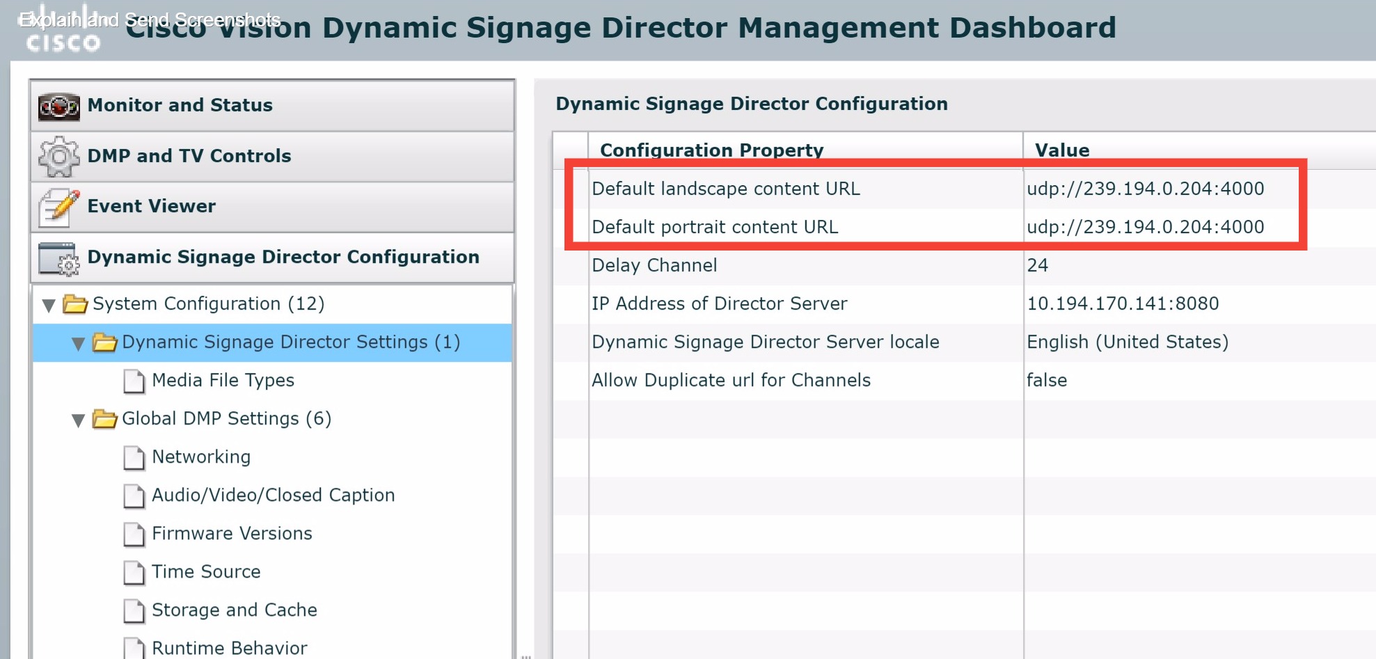
3.![]() In the Configuration Property, find the Default landscape content url and the Default portrait content url.
In the Configuration Property, find the Default landscape content url and the Default portrait content url.
4.![]() Type the URL of the content. The URL can be a video stream or an HTML page.
Type the URL of the content. The URL can be a video stream or an HTML page.
5.![]() Save the changes (click disk icon in bottom right of panel).
Save the changes (click disk icon in bottom right of panel).
Note: We do not recommend using portrait mode for the CV-HD and CV-HD2 media players.
Tuning Selected Media Players to a Multicast URL
You can tune one or more media players to a specific multicast URL in the Management Dashboard. This configuration will not remain after reboot of the devices but can be used as temporary workaround to a content issue at the venue. An easier way to tune the DMPS is to use Device Management. See Monitoring Media Player Operation During an Event Using Device Management.
To tune selected media players to a multicast URL:
1.![]() Go to More > Management Dashboard.
Go to More > Management Dashboard.
2.![]() Go to DMP and TV Controls > TV Commands > Set Video Channel .
Go to DMP and TV Controls > TV Commands > Set Video Channel .
3.![]() In the Command panel, Common tab, specify the URL for the multicast group (address and port) of the video channel that you want to display on the selected media players (Figure 2).
In the Command panel, Common tab, specify the URL for the multicast group (address and port) of the video channel that you want to display on the selected media players (Figure 2).
Figure 2 Tuning DMP to a Multicast URL
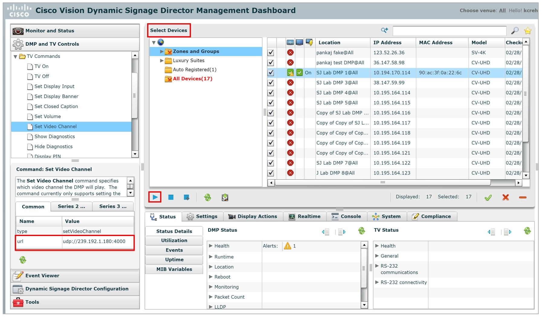
4.![]() In the Select Devices panel, select the media players whose TV displays should display this default channel.
In the Select Devices panel, select the media players whose TV displays should display this default channel.
5.![]() Click the Play button (bottom left) to send the command to the selected DMP.
Click the Play button (bottom left) to send the command to the selected DMP.
Defining Channels and Channel Guides
User Role: Administrator / Content Manager
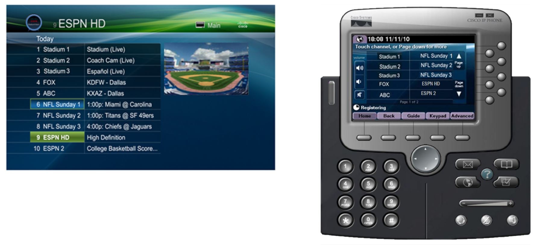
Cisco Vision Director allows you to tune in-house and external video channels, including over the air (OTA) local channels, satellite, and cable TV, when distributed by the appropriate headend system. Video can be in either high definition (HD) or standard definition (SD). The number of video channels you can offer depends on the available bandwidth in your network. The channels you select will be available for viewing anywhere you have TVs connected to DMPs: in bars and restaurants, the back office, and in luxury suites. Users can change channels from the IP Phone or using the IR remote.
Figure 3 Channel Guide Lineup on TV and IP Phone
Channel Lineup Designation at the Headend
A combination of external and internal channels make up the “channel lineup” that is available throughout the venue.
Although the concept of a channel number doesn’t really exist in the IP world, channel numbers are typically assigned to each channel at the head end. These numbers are arbitrary, but can be numbered to correspond to the channels that will show up on the IP phone control in the Luxury Suites.
To enable channel selection at the endpoints:
■![]() When the On the Cisco DCM is deployed, each (in-house or external) channel received is mapped to its unique multicast group address and UDP port number.
When the On the Cisco DCM is deployed, each (in-house or external) channel received is mapped to its unique multicast group address and UDP port number.
■![]() In Cisco Vision Director, each unique multicast group/UDP port number pair is assigned a Cisco Vision channel number and a channel name.
In Cisco Vision Director, each unique multicast group/UDP port number pair is assigned a Cisco Vision channel number and a channel name.
■![]() Cisco Vision Director uses this mapping to direct DMPs to specific channels and populate a channel guide which lists the available channels.
Cisco Vision Director uses this mapping to direct DMPs to specific channels and populate a channel guide which lists the available channels.
Note : For information about how to configure the channel lineup at the headend, see the Cisco StadiumVision Video Headend Design and Implementation Guide available to qualified Cisco Vision partners.
Defining the Master Channel List
Once channels have been defined at the headend, define a master channel list. Go to Configuration > Channel Definitions.
Consider the following before you configure the master channel list:
■![]() Channels to be offered: Decide how many in-house live video feeds you will have and which external channels you will offer.
Channels to be offered: Decide how many in-house live video feeds you will have and which external channels you will offer.
■![]() Channel Numbering Scheme: You may want in-house channels at the top of your numbering scheme. You may want your numbering scheme to match the area satellite or cable numbering scheme. You may choose to hide some of the channels you have in house.
Channel Numbering Scheme: You may want in-house channels at the top of your numbering scheme. You may want your numbering scheme to match the area satellite or cable numbering scheme. You may choose to hide some of the channels you have in house.
■![]() Channel Guide Appearance: Decide the channel guide descriptions that appear on the TVs in your luxury suites, bars, and restaurants and whether you want a channel logo to appear on the screen.
Channel Guide Appearance: Decide the channel guide descriptions that appear on the TVs in your luxury suites, bars, and restaurants and whether you want a channel logo to appear on the screen.
■![]() For each channel that should appear in the channel lineup accessed by a Cisco IP Phone or IR remote, set the “Visible in IP Phone Guide” field on the Channels panel to Yes.
For each channel that should appear in the channel lineup accessed by a Cisco IP Phone or IR remote, set the “Visible in IP Phone Guide” field on the Channels panel to Yes.
■![]() For each channel that is to appear in the channel lineup accessed by a third-party touch panel, set the “Visible in 3 rd Party Guide” field on the Channels panel to Yes.
For each channel that is to appear in the channel lineup accessed by a third-party touch panel, set the “Visible in 3 rd Party Guide” field on the Channels panel to Yes.
Adding Channels to the Master Channel List
User Role: Administrator / Content Manager
Note: Now you can upload a customizable background image for the Channel Guide. See Customizable Background Images for Login, DMP, or Channel Guide.
To add channels to the master channel list:
1.![]() Go to Configuration > Channel Definitions. The Master Channel List displays in the Master Channel List tab.
Go to Configuration > Channel Definitions. The Master Channel List displays in the Master Channel List tab.
2.![]() Click “+” to add a channel.
Click “+” to add a channel.
3.![]() On the Basic Info tab, define the information listed in Table 1. The items with an asterisk * are required.
On the Basic Info tab, define the information listed in Table 1. The items with an asterisk * are required.
Note: The Channel name configured in Cisco Vision Director should be limited to 12 characters or less. Due to the space allotted for channel names on the IP Phone interface, more than 12 characters may have undesirable results.
Table 1 Adding a Channel to the Master Channel List
4.![]() When you have filled in all the required fields, click Save. As soon as you save this channel, it will appear in the Master Channel List.
When you have filled in all the required fields, click Save. As soon as you save this channel, it will appear in the Master Channel List.
Note : You must Save before you add or modify another channel. As soon as you move from one channel to another without doing a save, all of your input is lost.
5.![]() Repeat steps 3 – 4 to add all the channels you want to display in Cisco Vision Director.
Repeat steps 3 – 4 to add all the channels you want to display in Cisco Vision Director.
Using “Favorites” (Third-Party Touch Panels Only)
All installations should move to access channels directly via the local control API versus indirectly through the legacy favorites mechanism. In addition to the channel lineup, a maximum of 10 channels can be identified as favorites, which appear on the initial video control page of the third-party touch panels.
For each channel that should be listed as a favorite:
■![]() In the Favorite field, select Yes.
In the Favorite field, select Yes.
■![]() In the Favorite Order field, enter a number (between 1 and 10) indicating the ordinal placement of this channel in the listing.
In the Favorite Order field, enter a number (between 1 and 10) indicating the ordinal placement of this channel in the listing.
Work with the third-party device integrator to determine how the favorites list should be displayed on the third-party touch panels.
Sorting the Master Channel List
Click the Master Channel List column headings (Name or #) to sort the channel names alphabetically in ascending or descending order or by channel number. You can also use the filter box to see only the subset of channels that have the characters you specify in the filter. The filter is not case sensitive.
Creating and Assigning Channel Guides
Once you have added channels to the Master Channel List, you can create “per-area channel guides” to display a custom channel guide in different areas of the venue. For example, you can have a different set of channels available in each of the suites, concourses, clubs, the owners suite, back offices, locker rooms, concessions and ticket windows.
The per-area channel guides are a subset of the master channel list, meaning the channel numbers and descriptions are preserved. For example, a venue may have raw in-house channels that they want to make available only to the coaching staff and not to the general public. To do this, create two channels guides: one private and one public. The private channel guide is assigned to groups/zones of DMPs that control the TVs in the coaches office and locker rooms. The public channel guide is flagged as the default channel guide and is automatically assigned to all other DMPs.
Designate one channel guide as the default channel guide. Only DMPs that are in a luxury suite are assigned a channel guide.
Note : If you make changes to a channel guide that is associated with an area serviced by a third-party touch panel, the third-party device must reload the latest channel guide information. Consult the third-party device integrator (AMX or Crestron) for reload options.
Creating a Channel Guide
User Role: Administrator / Content Manager
1.![]() Go to Configuration > Channel Guide (Figure 4). For more information, see Table 1.
Go to Configuration > Channel Guide (Figure 4). For more information, see Table 1.
Figure 4 Creating a Channel Guide
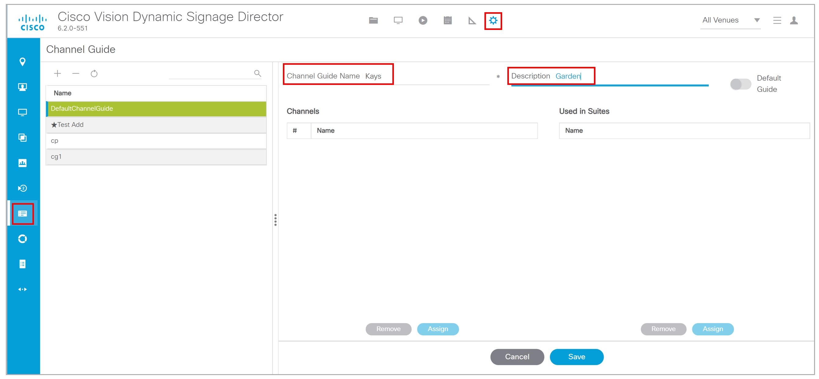
2.![]() Click the plus (+) and type a name and description for the new channel guide.
Click the plus (+) and type a name and description for the new channel guide.
3.![]() (Optional) Enable “Default Channel Guide for All Suites” to make this the default channel guide.
(Optional) Enable “Default Channel Guide for All Suites” to make this the default channel guide.
Assigning Channels to a Channel Guide
User Role: Administrator / Content Manager
To assign channels to a channel guide:
1.![]() Go to Configuration > Channel Guide and select the per area channel guide to which you want to assign channels.
Go to Configuration > Channel Guide and select the per area channel guide to which you want to assign channels.
2.![]() Click Assign. The Master Channel list displays.
Click Assign. The Master Channel list displays.
3.![]() Select the channels you want to add to the channel guide and click Add. The channels you add display in the Channel Guide window.
Select the channels you want to add to the channel guide and click Add. The channels you add display in the Channel Guide window.
TIP: To select multiple channels, use the keyboard Shift-click and Ctrl-click.
Assigning a Channel Guide to a Luxury Suite/Local Control Area
User Role: Administrator / Content Manager
IMPORTANT: A DMP should only be assigned to one luxury suite, especially if using the local control API.
Do this task after the Master Channel List and per area channel guide is created.
To assign a channel guide to a luxury suite:
1.![]() Go to Configuration > Channel Guide.
Go to Configuration > Channel Guide.
2.![]() Select the per-area channel guide.
Select the per-area channel guide.
3.![]() Click Assign (under the “ Used in Suites ” list). The list of undefined luxury suites/local control areas displays.
Click Assign (under the “ Used in Suites ” list). The list of undefined luxury suites/local control areas displays.
Note : The term “Luxury Suite” is used to define not only Luxury Suites but also any local control area.
4.![]() Select the luxury suites/local control area to which you want to assign the custom channel guide.
Select the luxury suites/local control area to which you want to assign the custom channel guide.
TIP: To select more than one suite/local control area, use the keyboard Shift-click and Ctrl-click.
By default, when the channel guide is brought up on the IP Phone, it is also displayed on the selected TV(s). You can change this behavior by setting the “tvguide.autolaunch” parameter to 0 in the Cisco Vision Director Management Dashboard Registry. See Controlling the Behavior of the Channel Guide.
Adding Icons to the IP Phone Channel Guide
You can associate channel icons that display in the IP Phone channel guide. Channel icons must be obtained locally (the venue must obtain permission from the network) and must be a 24 x 24 PNG file. The most common is a third-party channel icon file that is a 100 X 100 PNG.
Uploading a Channel Icon
Click the Icons tab to control uploading the channel icons to the IP Phones, the DMP/TV or Third-Party devices (Figure 5). Customize which icon is shown in certain contexts (like on-screen next to the name when it's chosen, in the channel banner, etc.). You can upload and tag multiple icons for the same usage type at the same time.
1.![]() Copy the icon graphic(s) to your local drive.
Copy the icon graphic(s) to your local drive.
2.![]() Go to Configuration > Channel Definitions.
Go to Configuration > Channel Definitions.
3.![]() Click the Master Channel List tab and the Icon tab. The icon list displays (Figure 5).
Click the Master Channel List tab and the Icon tab. The icon list displays (Figure 5).
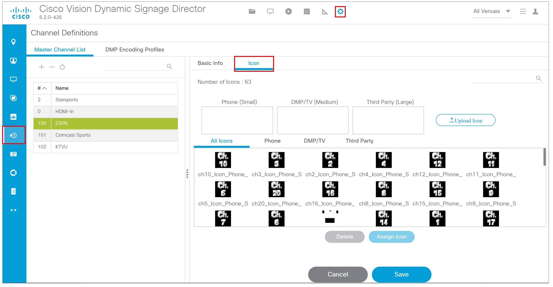
4.![]() Click Upload Icon and browse to the.png file you want to assign as a channel icon.
Click Upload Icon and browse to the.png file you want to assign as a channel icon.
5.![]() In the Import Icons dialog box, select where the channel icon will be used (Icon category) from the drop-down menu (Figure 6).
In the Import Icons dialog box, select where the channel icon will be used (Icon category) from the drop-down menu (Figure 6).
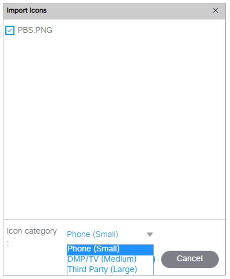
6.![]() Select an expiration setting.
Select an expiration setting.
7.![]() Click Upload. The icon you uploaded will now appear in the icon list.
Click Upload. The icon you uploaded will now appear in the icon list.
Assigning a Channel Icon
User Role: Administrator / Content Manager
Once you have created a master channel list and uploaded phone channel icons, assign icons to the channels.
1.![]() Select Configuration > Channel Definitions.
Select Configuration > Channel Definitions.
2.![]() Click the Master Channel List tab and the Icon tab. The icon list displays.
Click the Master Channel List tab and the Icon tab. The icon list displays.
3.![]() In the icon list, select the channel for which you want to assign an icon. The channel number displays in the Assigned Icons box.
In the icon list, select the channel for which you want to assign an icon. The channel number displays in the Assigned Icons box.
4.![]() Select the icon you want to assign to the channel.
Select the icon you want to assign to the channel.
6.![]() Click Save. A message displays confirming the icon assignment was successful.
Click Save. A message displays confirming the icon assignment was successful.
Channel Guide Behavior
IMPORTANT: When using the Local Control API, unpredictable results may occur if you assign a DMP to more than one luxury suite.
■![]() If a DMP is assigned to more than one Luxury Suite, it will use the Per-Area Channel Guide associated with the last Luxury Suite to which it was assigned. For example if a DMP is added to Suite 1 and then added to Suite 2, it will use the Channel Guide defined for Suite 2. For this reason, it is recommended that you do not assign a DMP to more than one Luxury Suite.
If a DMP is assigned to more than one Luxury Suite, it will use the Per-Area Channel Guide associated with the last Luxury Suite to which it was assigned. For example if a DMP is added to Suite 1 and then added to Suite 2, it will use the Channel Guide defined for Suite 2. For this reason, it is recommended that you do not assign a DMP to more than one Luxury Suite.
■![]() If the user changes the channel via an IP phone, IR remote, or 3rd-Party remote, the channel chosen by the user will override the currently playing video playlist with the selected video.
If the user changes the channel via an IP phone, IR remote, or 3rd-Party remote, the channel chosen by the user will override the currently playing video playlist with the selected video.
■![]() If the template has a primary video region assigned to a video channel, the template will not change, but the video will change to the selected channel.
If the template has a primary video region assigned to a video channel, the template will not change, but the video will change to the selected channel.
■![]() If the template has no primary video region, the display will be replaced with full screen video showing the selected channel.
If the template has no primary video region, the display will be replaced with full screen video showing the selected channel.
■![]() If the DMP is showing a playlist of video, the entire playlist will be replaced by the single video channel. For example, if the playlist contains three videos, all three videos will stop and be replaced by the selected channel. Only one video in a playlist will play.
If the DMP is showing a playlist of video, the entire playlist will be replaced by the single video channel. For example, if the playlist contains three videos, all three videos will stop and be replaced by the selected channel. Only one video in a playlist will play.
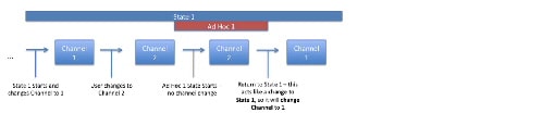
■![]() When the state changes on a DMP that is associated with a local control area (luxury suite, bar, restaurant, etc.), the script contents will override the user's local control.
When the state changes on a DMP that is associated with a local control area (luxury suite, bar, restaurant, etc.), the script contents will override the user's local control.
Therefore, if you expect a DMP to be locally controlled, any states in use during that period should not change the template or channel. This is particularly important when using ad hoc states with locally controlled DMPs. Cisco Vision Director will treat the return from an ad hoc as a state change, so if the base state has a channel setting, the channel on all locally controlled DMPs will return to the base channel when the ad hoc state ends.
Controlling the Behavior of the Channel Guide
The appearance and behavior of the channel guide are controlled by parameters in the Cisco Vision Director registry. These settings control whether:
■![]() A preview window is displayed when a channel is selected.
A preview window is displayed when a channel is selected.
■![]() The channel guide is automatically displayed on the TV when it is selected on the phone.
The channel guide is automatically displayed on the TV when it is selected on the phone.
■![]() The phone UI continues to display the channel guide after a channel has been selected.
The phone UI continues to display the channel guide after a channel has been selected.
Note: For individual luxury suites, you can override the setting that controls the automatic display of the channel guide on the TV through Script Management.
Note: For URL channels, the preview window will show the HTML content. The DMP will not scale this HTML content. We highly recommend that the URL channels be responsive to the region size.
Configuring Channel Guide Settings in the Registry
To configure channel guide settings in the registry:
1.![]() Go to More > Management Dashboard > Tools drawer > Advanced tab > Registry . To be sure that you are displaying the current settings, click Load.
Go to More > Management Dashboard > Tools drawer > Advanced tab > Registry . To be sure that you are displaying the current settings, click Load.
2.![]() Scroll through the Registry Data list to the desired parameters.
Scroll through the Registry Data list to the desired parameters.
Note : To change the phoneControl.stayOnChannelSelect parameter from its default (1), you must add the parameter using Add Row.
3.![]() Click the Value field beside each parameter and enter the appropriate values.
Click the Value field beside each parameter and enter the appropriate values.
Defining a Delay Channel
User Role: Administrator / Content Manager
If you have assigned DMPs to a delay zone, then you can configure the channel you want to display on the TVs controlled by the DMPs in the delay zone during the delay event state.
If no channel is configured, the DMPs will display the default channel during the delay event state.
1.![]() Click Script Management and select the event script.
Click Script Management and select the event script.
3.![]() Click the plus sign (+) below the Ad Hoc States tab. The Add State box appears.
Click the plus sign (+) below the Ad Hoc States tab. The Add State box appears.
4.![]() Enable the Manual transition button (the default setting).
Enable the Manual transition button (the default setting).
5.![]() In the Ad Hoc State box, click Edit.
In the Ad Hoc State box, click Edit.
6.![]() Select the delay group from the tree list.
Select the delay group from the tree list.
7.![]() Select the Set FULLSCREEN action source and drag it to the Assigned Actions list.
Select the Set FULLSCREEN action source and drag it to the Assigned Actions list.
9.![]() Select the channel you want to play during a delay from the Playlist Sources channels list.
Select the channel you want to play during a delay from the Playlist Sources channels list.
Defining a Non-Event Channel
User Role: Administrator / Content Manager
If you have assigned DMPs to a non-event zone, you can configure the channel you want the TVs to play when no event script is running in that non-event zone.
If no channel is configured, the DMPs will display the default channel during the non-event state.
To define a non-event channel:
2.![]() Click the plus sign (+) above the Ad Hoc states panel. The Add State box appears.
Click the plus sign (+) above the Ad Hoc states panel. The Add State box appears.
3.![]() Enable the Manual transition button (the default setting).
Enable the Manual transition button (the default setting).
4.![]() In the Ad Hoc State box, click Edit.
In the Ad Hoc State box, click Edit.
5.![]() Select your non-event group from the tree list.
Select your non-event group from the tree list.
6.![]() Select the Set FULLSCREEN action source and drag it to the Assigned Actions list.
Select the Set FULLSCREEN action source and drag it to the Assigned Actions list.
8.![]() Select the channel you want to play when no event script is running from the Playlist Sources channels list.
Select the channel you want to play when no event script is running from the Playlist Sources channels list.
Setup Channel Source Types
There is a channel source type called External URL that allows you to specify an HTTP, HTTPS, or HTTP Live Streaming (HLS) source as a channel, including HTML page sources.
HLS sources are hardware-accelerated on the DMP. The content is specified as an External URL source type in the Channels setup. The system recognizes the content as an HLS source based on the Allowed HLS file formats designated in the Management Dashboard. The default extensions allowed are m3u and m3u8 . See the Cisco Vision Dynamic Signage Director Release Notes for Release 6.2.
Note: This feature does not replace the existing HTML pass-through feature (External Content) from the Library screen.
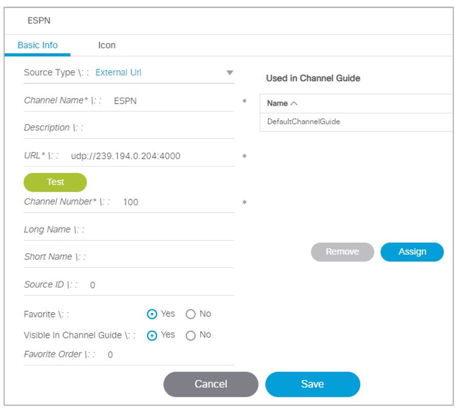
The Source Type field is available with Video Stream, External URL, and HDMI-In options (Figure 7).
1.![]() Go to Configuration > Channel Definitions.
Go to Configuration > Channel Definitions.
3.![]() At the Source Type pull-down, select External URL to choose an external url for your channel (Figure 7).
At the Source Type pull-down, select External URL to choose an external url for your channel (Figure 7).
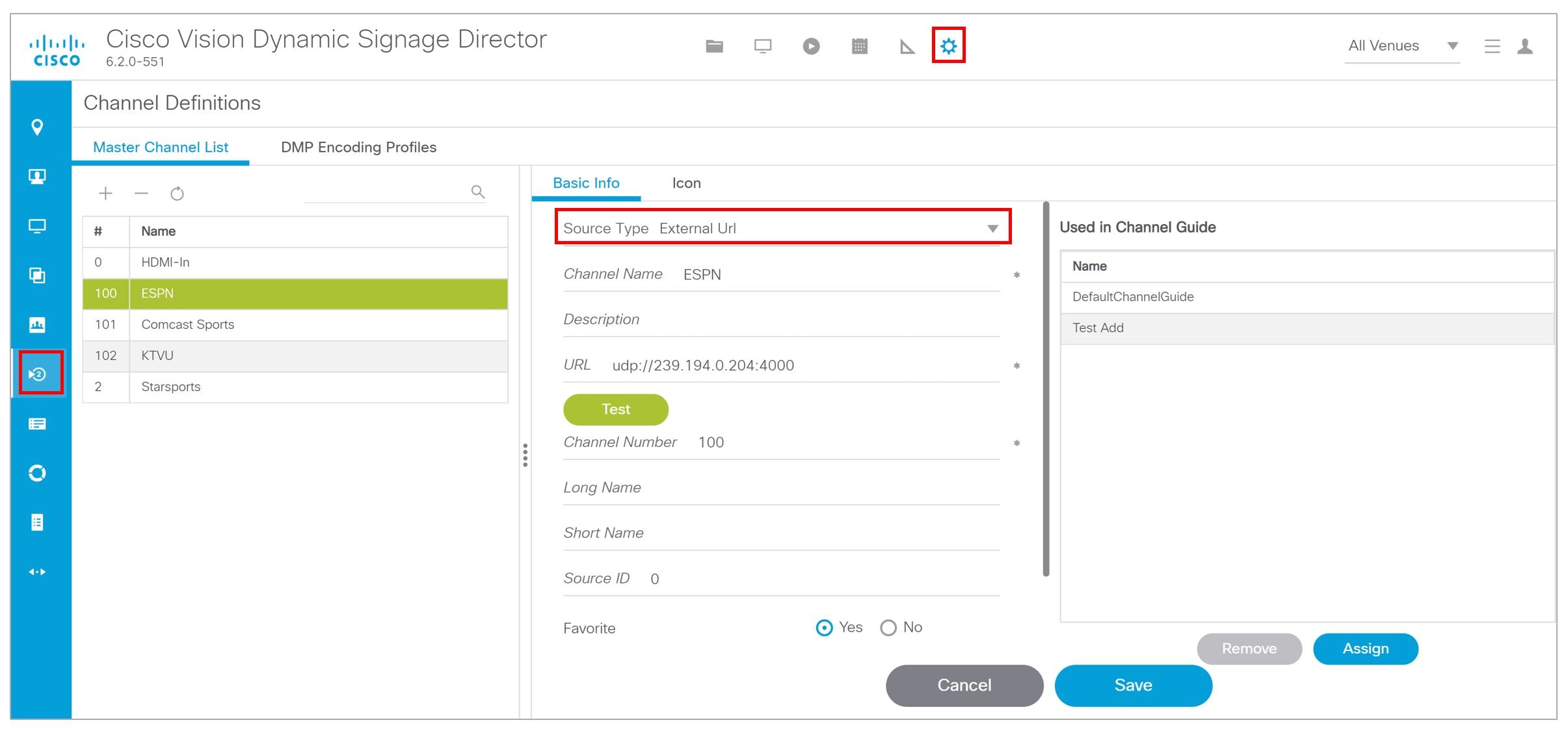
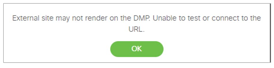
To test the external URL to see if it has X-Frame option, add the URL into the field and click Test.
If the URL will not render on the DMP, you may get an error message (Figure 8). If it passes, click Save.
Figure 8 Testing the External URL, Error
To test a new External URL from the Library:
1.![]() Right click External Content > Create. The New External Content dialog box appears (Figure 9).
Right click External Content > Create. The New External Content dialog box appears (Figure 9).
Figure 9 New External Content Dialog Box
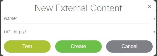
2.![]() Type in the Name and the URL.
Type in the Name and the URL.
3.![]() Click Test. You may see an error message here if this external URL cannot render on the DMP.
Click Test. You may see an error message here if this external URL cannot render on the DMP.
4.![]() If it passes, click Create. The URL will be stored and will push to the DMP (Figure 10).
If it passes, click Create. The URL will be stored and will push to the DMP (Figure 10).
Figure 10 Test New External URL from Library
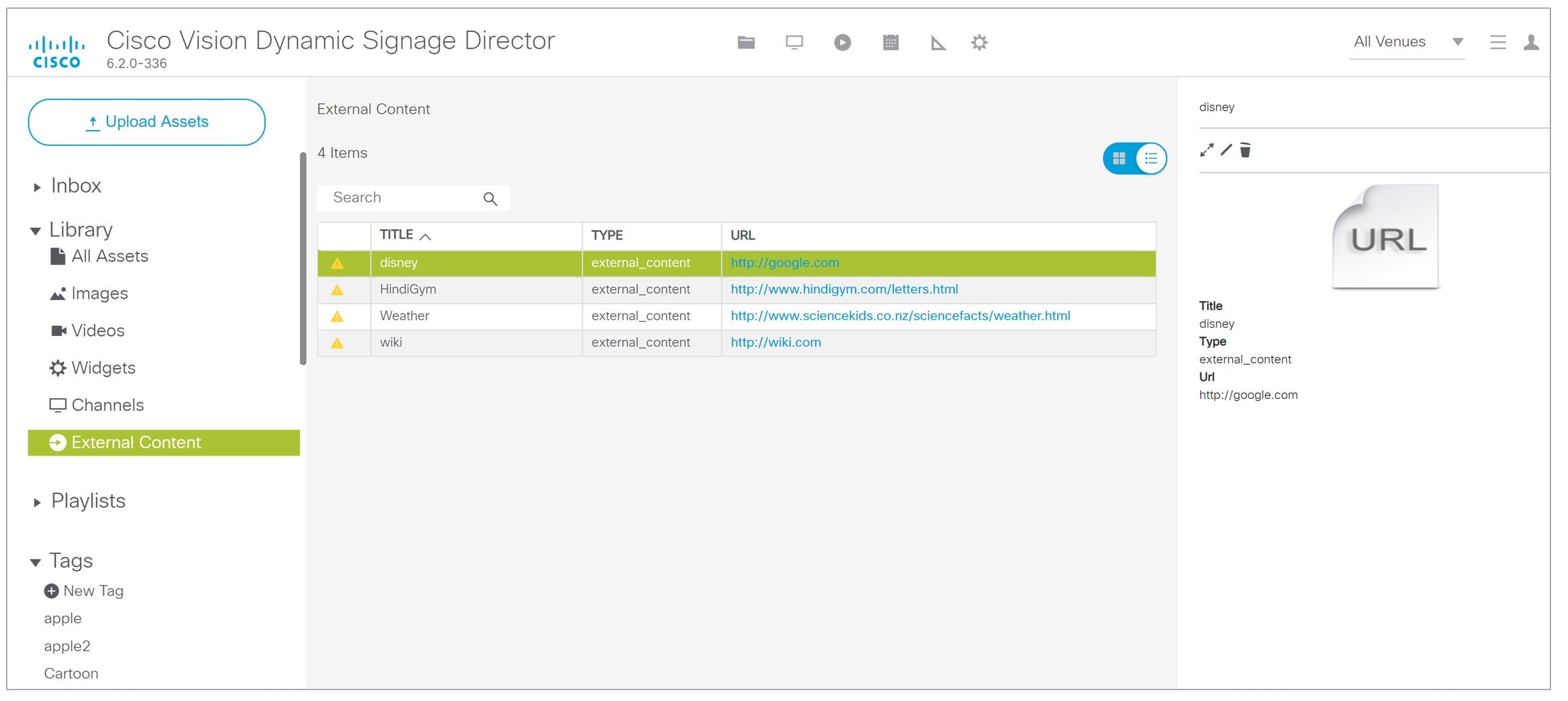
Use an external URL as a channel when you do not need synchronization of content, but you would like to be able to tune to that content from a script, User Control API, IP phone, or IR remote (Figure 11). External URL channels also can be streamed to a DMP-encoded multicast channel but do not support audio when streamed in that form.
Figure 11 External URL Dialog Box
Frameless External HTML Browser
You can render a full-screen external HTML page without the constraints of being in an I-frame. Supply a valid URL to a new script action command, StartWebApp, in the Edit Action dialog box (Figure 12). The URLs are not managed as External URL content or External URL channels which are both rendered inside an I-frame.
Figure 12 StartWebApp for Frameless External HTML Browsers
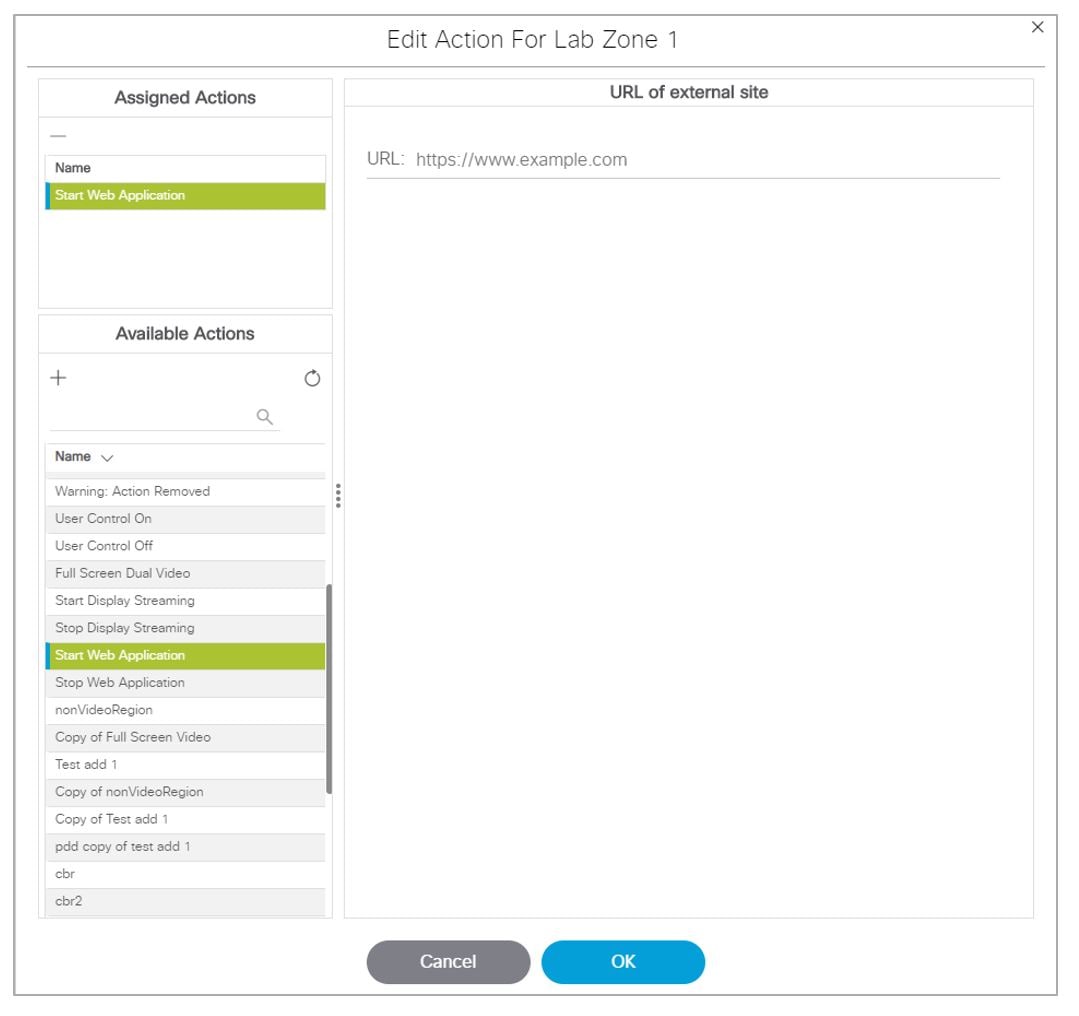
Using the StartWebApp action, a new browser will be launched and is rendered on top of the template-based content. Use the corresponding StopWebApp to close a web page rendered via StartWebApp. If two or more successive StartWebApp commands are received by the DMP, the Cisco Vision Director runtime will invoke the StopWebApp implicitly to guarantee that only one browser is overlaid on top of the runtime.
Web pages launched via StartWebApp can outlive the script that spawned them. Use the same StartWebApp/StopWebApp commands in Management Dashboard to separately manage the overlay browser.
■![]() Certificates are shared between the Cisco Vision Director runtime and the browser overlay.
Certificates are shared between the Cisco Vision Director runtime and the browser overlay.
■![]() Custom fonts are not shared. Custom fonts are not accessible by the browser overlay. We suggest using webfonts so that pages are rendered the way the content creators meant these to be rendered.
Custom fonts are not shared. Custom fonts are not accessible by the browser overlay. We suggest using webfonts so that pages are rendered the way the content creators meant these to be rendered.
■![]() The webdb and indexdb storage settings will also apply to the browser overlay. Adjust the available memory you want to use in the asset pool accordingly if you decide to use browser overlay.
The webdb and indexdb storage settings will also apply to the browser overlay. Adjust the available memory you want to use in the asset pool accordingly if you decide to use browser overlay.
Configuring HDMI-In Video Sources on the SV-4K, CV-UHD, and CV-UHD2 Media Players
This section includes the following topics:
■![]() Guidelines for Using HDMI-In on the SV-4K, CV-UHD, and CV-UHD2 DMPs
Guidelines for Using HDMI-In on the SV-4K, CV-UHD, and CV-UHD2 DMPs
■![]() Prerequisites for Using HDMI-In on the SV-4K, CV-UHD, and CV-UHD2
Prerequisites for Using HDMI-In on the SV-4K, CV-UHD, and CV-UHD2
■![]() Restrictions for Using HDMI-In on the SV-4K, CV-UHD, and CV-UHD2
Restrictions for Using HDMI-In on the SV-4K, CV-UHD, and CV-UHD2
■![]() Configuring HDMI-In as a Video Source in a Region on the SV-4K, CV-UHD, and CV-UHD2 Media Players
Configuring HDMI-In as a Video Source in a Region on the SV-4K, CV-UHD, and CV-UHD2 Media Players
■![]() Configuring a DMP-Encoded Multicast Channel on the SV-4K, CV-UHD, or CV-UHD2 DMPs
Configuring a DMP-Encoded Multicast Channel on the SV-4K, CV-UHD, or CV-UHD2 DMPs
■![]() Starting and Stopping HDMI-In Streaming on the SV-4K, CV-UHD, and CV-UHD2 Media Players
Starting and Stopping HDMI-In Streaming on the SV-4K, CV-UHD, and CV-UHD2 Media Players
■![]() HDMI-In Streaming Versus Display Streaming
HDMI-In Streaming Versus Display Streaming
Guidelines for Using HDMI-In on the SV-4K, CV-UHD, and CV-UHD2 DMPs
When using HDMI-In on the DMPs, consider the following guidelines:
■![]() If using video with UHD resolution, be sure to observe the guidelines for UHD content in the Cisco Vision Content Planning and Specification Guide and use cables that are HDMI version 1.4 compliant.
If using video with UHD resolution, be sure to observe the guidelines for UHD content in the Cisco Vision Content Planning and Specification Guide and use cables that are HDMI version 1.4 compliant.
■![]() You can use different forms of local control only when using HDMI-In encoding to stream video as a multicast channel. Otherwise, use scripts to start/stop streaming.
You can use different forms of local control only when using HDMI-In encoding to stream video as a multicast channel. Otherwise, use scripts to start/stop streaming.
■![]() If you want to maintain privacy of channels, create a DMP-encoded channel per suite with a unique multicast address (from 239.193.20.0/24 range) and create a separate channel guide per suite.
If you want to maintain privacy of channels, create a DMP-encoded channel per suite with a unique multicast address (from 239.193.20.0/24 range) and create a separate channel guide per suite.
For example, if you have 10 suites:
1.![]() Create 10 separate DMP-encoded channels with unique multicast addresses.
Create 10 separate DMP-encoded channels with unique multicast addresses.
2.![]() Create 10 different channel guides for each DMP-encoded channel.
Create 10 different channel guides for each DMP-encoded channel.
Prerequisites for Using HDMI-In on the SV-4K, CV-UHD, and CV-UHD2
Before you use HDMI-In on the DMPs, be sure that the following conditions are met:
■![]() You have purchased a separate encoder software license. For more information, see the Cisco Vision Dynamic Signage Director Release Notes for 6.2.
You have purchased a separate encoder software license. For more information, see the Cisco Vision Dynamic Signage Director Release Notes for 6.2.
■![]() Test the devices that you plan to connect to the DMP HDMI-In port to stream content for HDCP support.
Test the devices that you plan to connect to the DMP HDMI-In port to stream content for HDCP support.
■![]() Most Mac OS and Windows laptops should work for HDMI-In video encoding for non-copy-protected content. It is up to the device manufacturer and OS whether or not this is supported.
Most Mac OS and Windows laptops should work for HDMI-In video encoding for non-copy-protected content. It is up to the device manufacturer and OS whether or not this is supported.
■![]() When using HDMI-In encoded video channels, be sure that you have configured the allowable multicast range 239.193.20.0/24 for this feature in the network requirements. See Cisco Vision Dynamic Signage Solution Operation and Network Requirements.
When using HDMI-In encoded video channels, be sure that you have configured the allowable multicast range 239.193.20.0/24 for this feature in the network requirements. See Cisco Vision Dynamic Signage Solution Operation and Network Requirements.
Restrictions for Using HDMI-In on the SV-4K, CV-UHD, and CV-UHD2
Before you use HDMI-In on the DMPs, consider the following restrictions:
IMPORTANT: The HDMI-In port on the SV-4K, CV-UHD, and CV-UHD2 digital media players can only be supported either as a source to video region or source to encoder as a channel, but not both. Therefore, you cannot have a script in a state which tunes to the HDMI-In as video source in a region, and then transition to the next state where you are streaming video from HDMI-In.
■![]() Videos with UHD resolution are not supported for HDMI-In streaming.
Videos with UHD resolution are not supported for HDMI-In streaming.
■![]() When using HDMI-In encoding to stream video content as a multicast channel:
When using HDMI-In encoding to stream video content as a multicast channel:
–![]() The streaming state is synchronized only when streaming is started by script, IP phone, IR remote, or User Control API—not when started from the Management Dashboard.
The streaming state is synchronized only when streaming is started by script, IP phone, IR remote, or User Control API—not when started from the Management Dashboard.
This means that if you start streaming from the Management Dashboard, then the IR remote menu might not properly show which channel is streaming or not streaming.
–![]() The DMPs playing HDMI-In encoded video stops streaming if the DMP is rebooted, even though the script is running. Start Streaming is a direct command, which is sent when the svd server changes state (like RS232 commands or tv on /off type commands). It is only executed when the state is changed, so it is not re-executed on reboot.
The DMPs playing HDMI-In encoded video stops streaming if the DMP is rebooted, even though the script is running. Start Streaming is a direct command, which is sent when the svd server changes state (like RS232 commands or tv on /off type commands). It is only executed when the state is changed, so it is not re-executed on reboot.
Configuring HDMI-In as a Video Source in a Region on the SV-4K, CV-UHD, and CV-UHD2 Media Players
User Role: Administrator / Content Manager
To configure HDMI-In as a video source in a region:
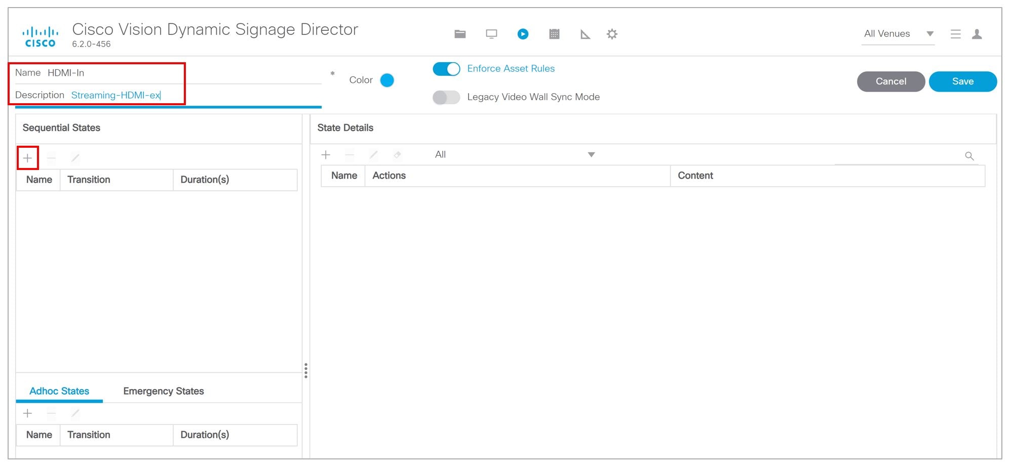
2.![]() Click the + sign to add (create) a new script (Figure 13). The States screen appears.
Click the + sign to add (create) a new script (Figure 13). The States screen appears.
3.![]() Type HDMI-In for Name (as an example, only).
Type HDMI-In for Name (as an example, only).
4.![]() Type Streaming-HDMI in the Description (Figure 14).
Type Streaming-HDMI in the Description (Figure 14).
Figure 14 Creating a New Script
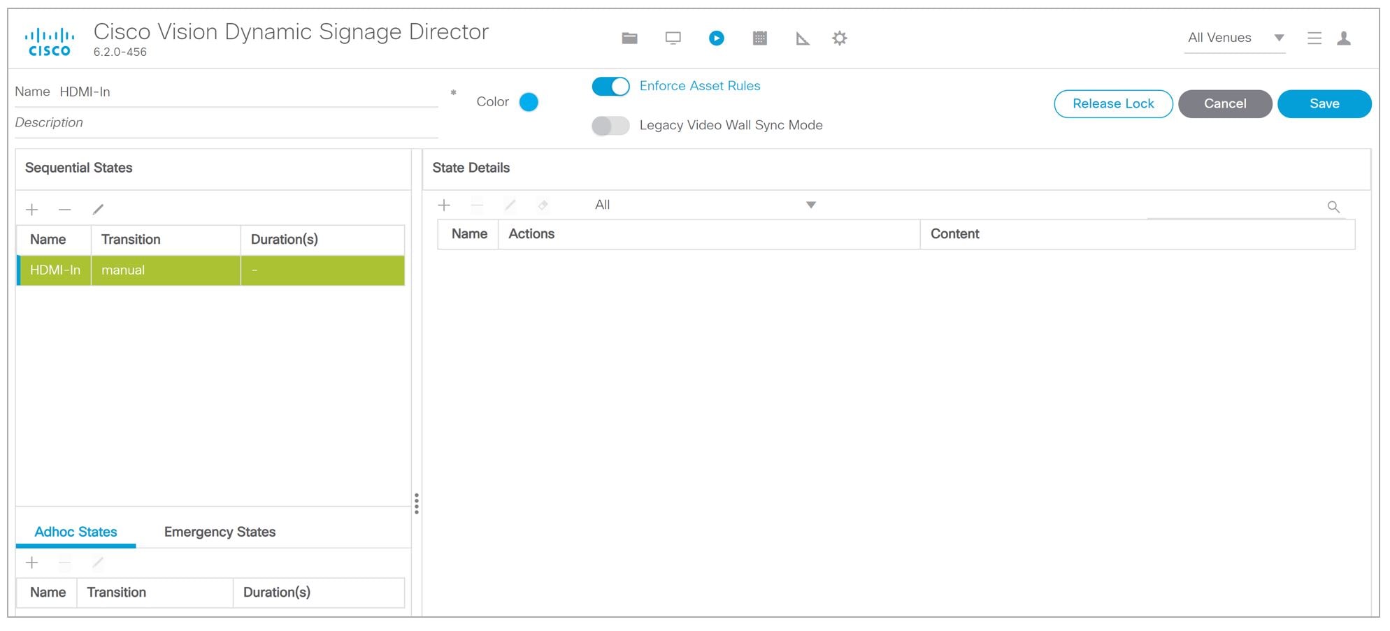
5.![]() Click the + in the Sequential States panel. The Add State box appears (Figure 15).
Click the + in the Sequential States panel. The Add State box appears (Figure 15).

6.![]() Add the state named HDMI-In State. Click Add. A confirmation box appears. The screen changes back to show the new script.
Add the state named HDMI-In State. Click Add. A confirmation box appears. The screen changes back to show the new script.
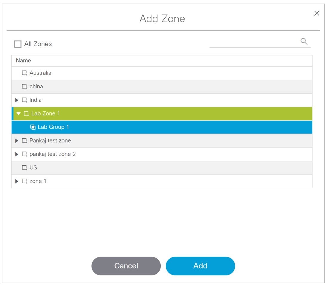
7.![]() Click the + in the State Details panel to select the group/zone where the event script should run to assign actions and content to the HDMI-In State (Figure 16).
Click the + in the State Details panel to select the group/zone where the event script should run to assign actions and content to the HDMI-In State (Figure 16).
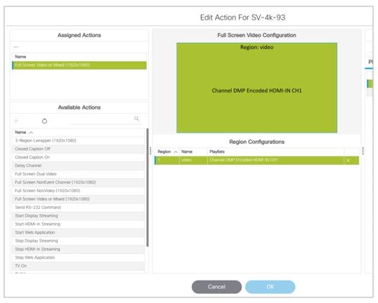
8.![]() Once you add a zone, click the Add button, select the Edit icon in the State screen. The Edit Actions box appears (Figure 17).
Once you add a zone, click the Add button, select the Edit icon in the State screen. The Edit Actions box appears (Figure 17).
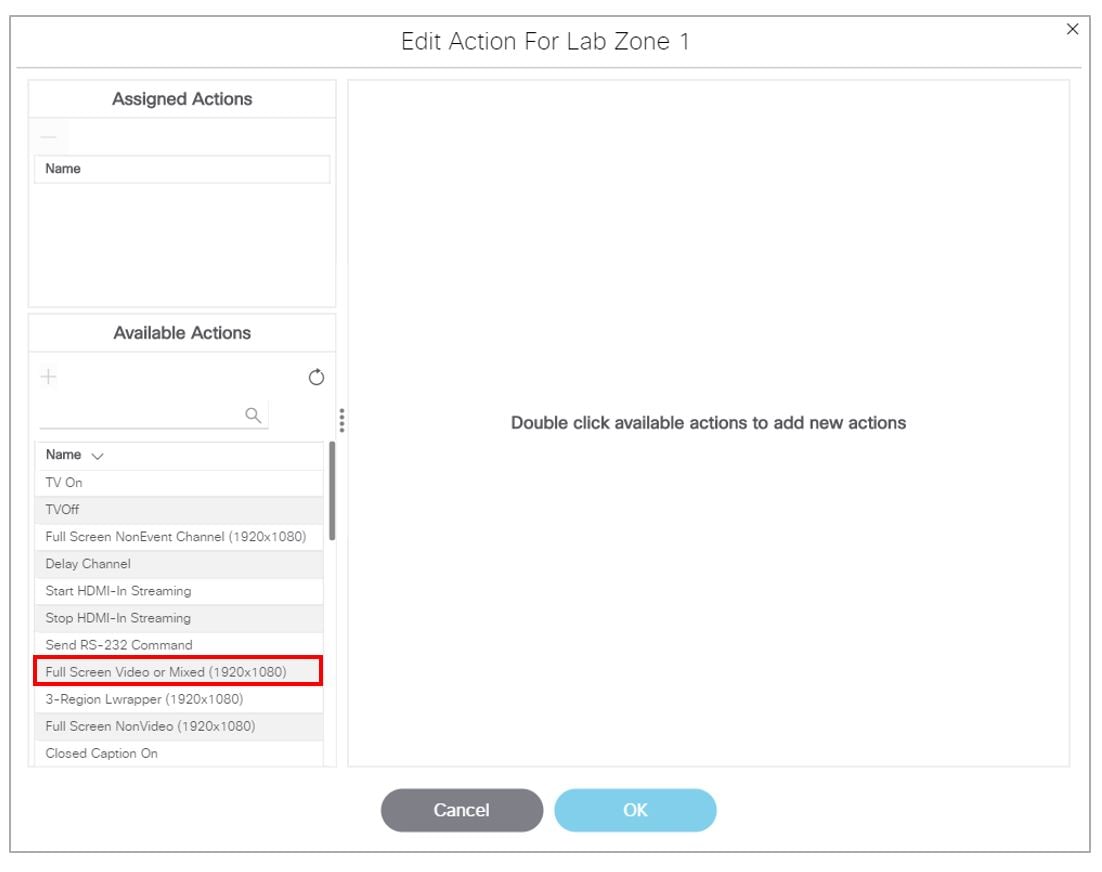
9.![]() Double click an Available Action from the list. In this example, the Full Screen Video or Mixed. The Edit Action box updates.
Double click an Available Action from the list. In this example, the Full Screen Video or Mixed. The Edit Action box updates.
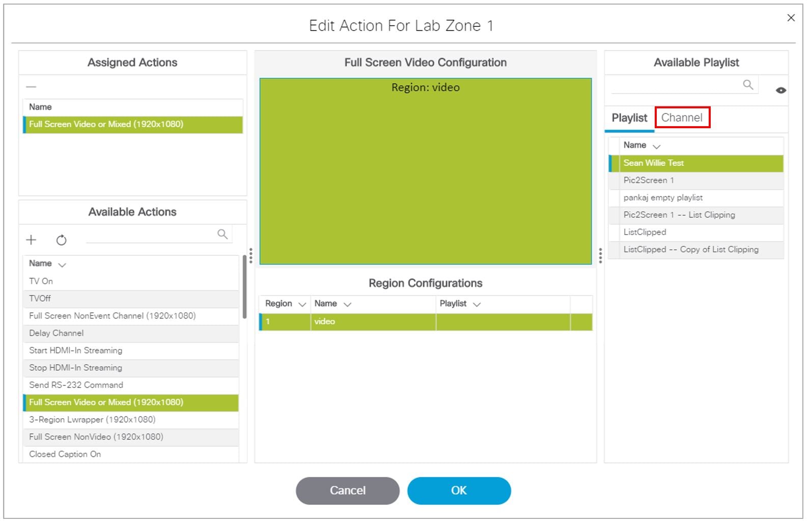
11.![]() Drag HDMI-In to a template region.
Drag HDMI-In to a template region.
12.![]() Click OK to save the script.
Click OK to save the script.
Note: Return to the Script Details screen by clicking the Script Management icon.
Verifying the Script Plays Local HDMI-In Content
To verify that the script plays the local HDMI-In content:
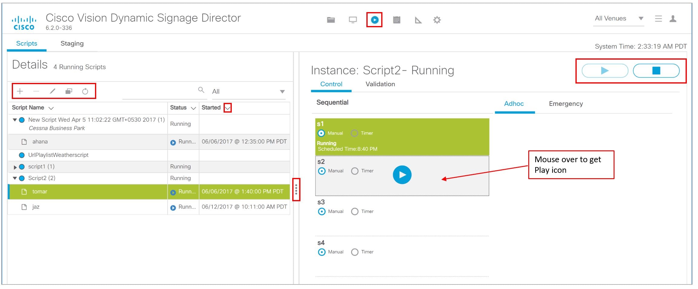
2.![]() Select the script and click Start (Figure 18). The Start Script dialog box appears (Figure 19).
Select the script and click Start (Figure 18). The Start Script dialog box appears (Figure 19).
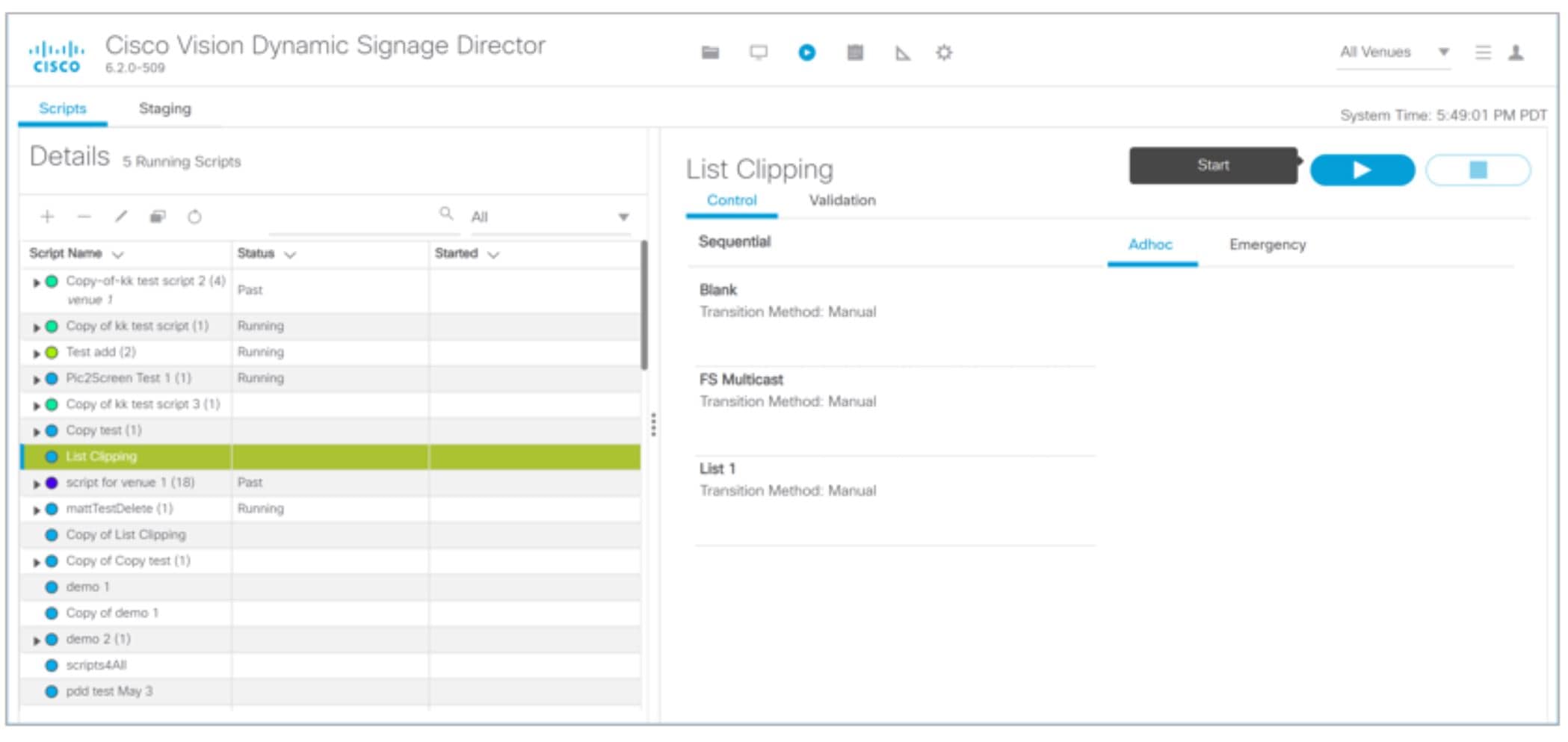
Figure 19 Start Script Dialog Box
5.![]() Start the HDMI-In_State. Verify that the TV display for the target DMP is playing the expected HDMI-In content.
Start the HDMI-In_State. Verify that the TV display for the target DMP is playing the expected HDMI-In content.
Configuring a DMP-Encoded Multicast Channel on the SV-4K, CV-UHD, or CV-UHD2 DMPs
User Role: Administrator / Content Manager
To configure a DMP-encoded multicast channel on the DMPs:
1.![]() Go to Configuration > Channel Definitions.
Go to Configuration > Channel Definitions.
2.![]() Select or create a channel guide where you want to include the DMP-encoded channel.
Select or create a channel guide where you want to include the DMP-encoded channel.
TIP: If you want to maintain privacy of channels, create a DMP-encoded channel per suite with a unique multicast address (from 239.193.20.0/24 range) and create a separate channel guide per suite.
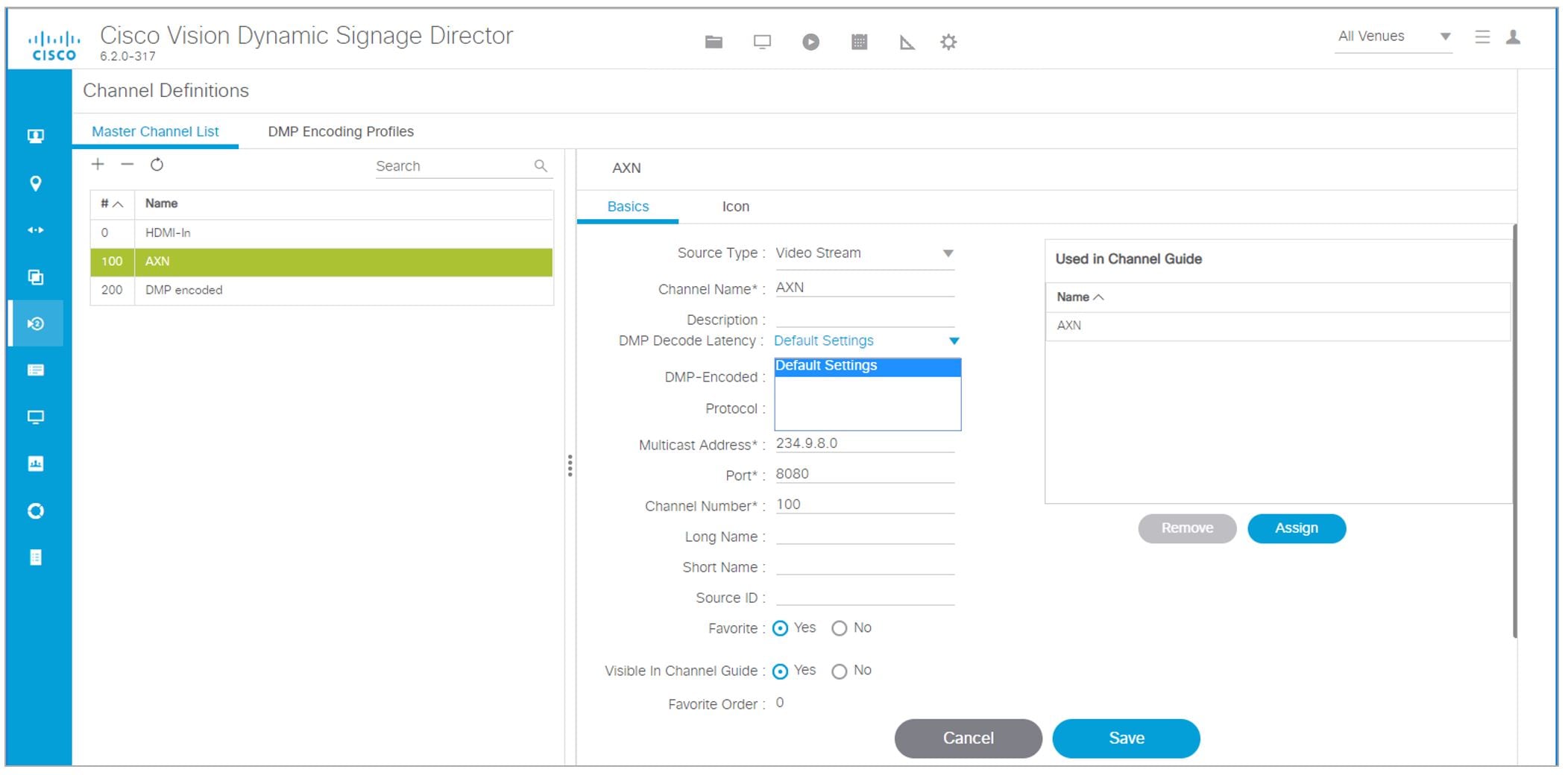
3.![]() From the Basic Info tab, configure the options shown in Figure 20 and described in Table 2.
From the Basic Info tab, configure the options shown in Figure 20 and described in Table 2.
Figure 20 DMP-Encoded Multicast Channel Example

Table 2 DMP-Encoded Multicast Channel Options
DMP Encoding Profiles
New to Release 6.2 is a DMP Encoding Profiles tab. There are three new encoding profiles to choose from in the Master Channel List tab (Figure 21).
Figure 21 Setting a Custom Video Profile for DMP-Encoded Information
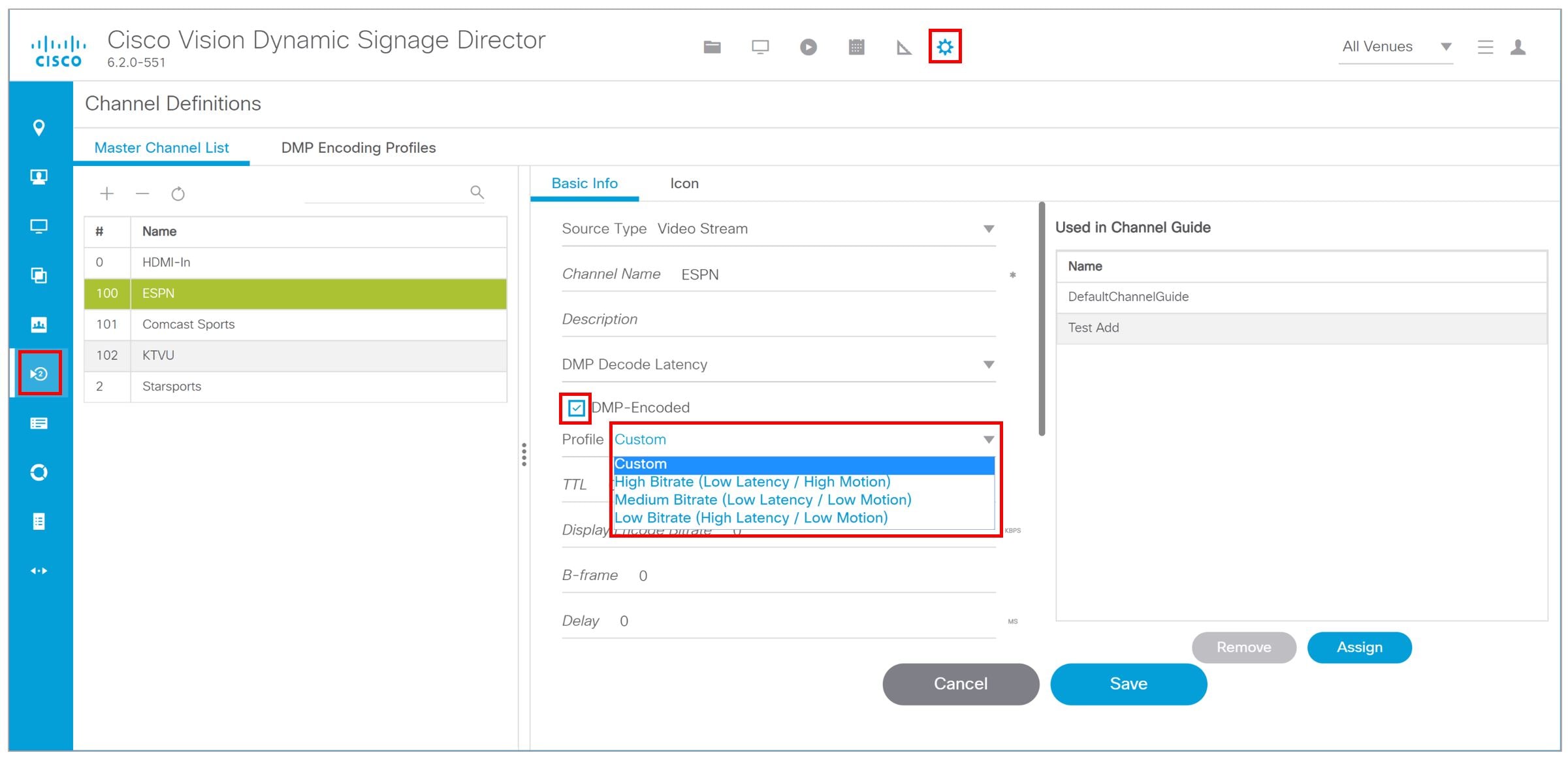
The available encoding profiles are:
■![]() Custom: you set the bitrate and latency
Custom: you set the bitrate and latency
■![]() High Bitrate (Low Latency / High Motion)
High Bitrate (Low Latency / High Motion)
■![]() Medium Bitrate (Low Latency / Low Motion)
Medium Bitrate (Low Latency / Low Motion)
■![]() Low Bitrate (High Latency / Low Motion)
Low Bitrate (High Latency / Low Motion)
For every newly created DMP-encoded channel, select one of the encoding profiles. For pre-existing DMP-encoded channels like those in Release 6.1 and older, the earlier settings are preserved and the encoded profile becomes Custom. This provides backward compatibility and we recommended you select any one of the Encoding Profiles listed.
Best practice: Set the encoding profiles on any pre-existing channels from Release 6.1 or older. If you know your videos will contain low-motion, you can choose the low or medium bit rates for low-motion video. This helps the DMP adjust the jitter so your content displays best.
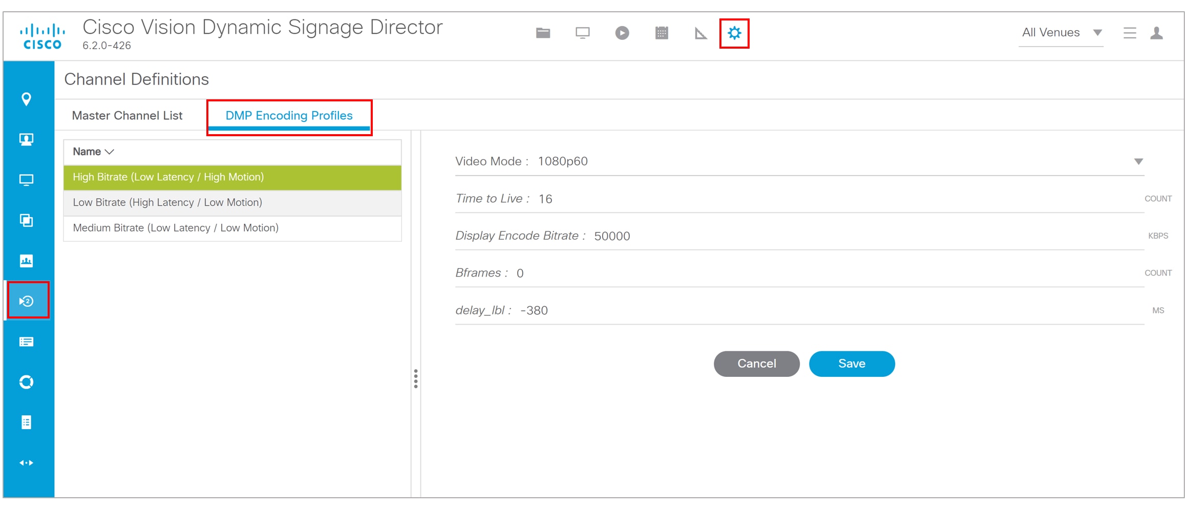
To choose an encoding profile:
1.![]() Go to Configuration > Channel Definition.
Go to Configuration > Channel Definition.
2.![]() Select an encoding profile from the drop-down.
Select an encoding profile from the drop-down.
3.![]() Click the DMP Encoding Profiles tab. The Detail screen appears (Figure 22) showing the suggested Video Mode, Display Encode Bitrate, Bframes and Delay. Click Save.
Click the DMP Encoding Profiles tab. The Detail screen appears (Figure 22) showing the suggested Video Mode, Display Encode Bitrate, Bframes and Delay. Click Save.
Figure 22 DMP Encoding Profile Details
DMP Decode Latency, Configured per Channel
This feature allows you to choose the latency setting you want on a per channel basis.
There are three Decode Latency Settings options available to Channel Definitions (Figure 23). Pick the channel and use the Default Setting or the Alternate Setting from the drop-down.
Figure 23 Setting Decode Latency Per Channel
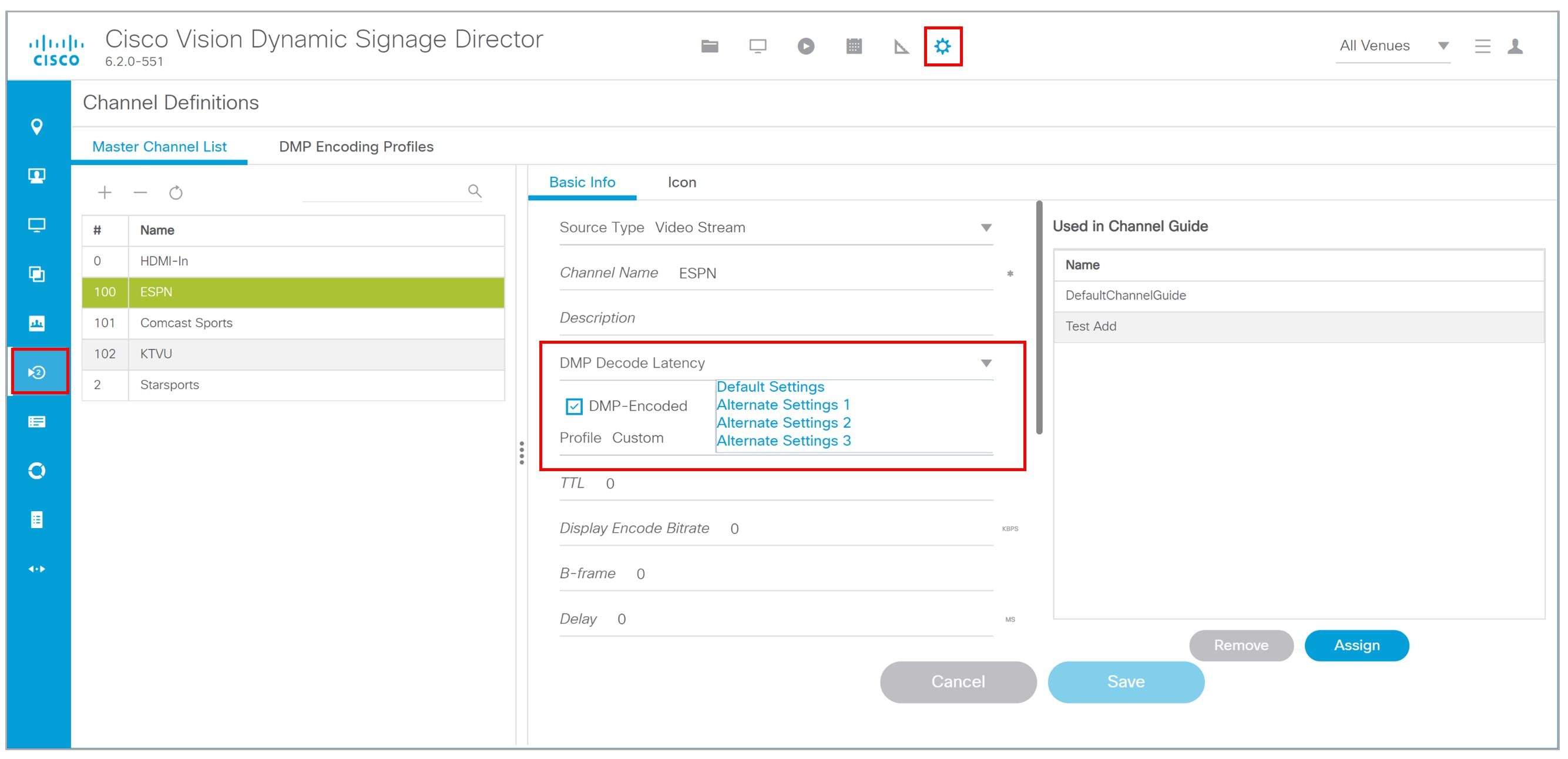
Set the Alternate Latency setting parameters in Management Dashboard.
To set the DMP decode latency:
1.![]() Go to More > Management Dashboard > Dynamic Signage Director Configuration > System Configuration > Global DMP Settings > Decode Latency 1 (Figure 24).
Go to More > Management Dashboard > Dynamic Signage Director Configuration > System Configuration > Global DMP Settings > Decode Latency 1 (Figure 24).
2.![]() Set all the values for the available configuration properties.
Set all the values for the available configuration properties.
4.![]() Go to Configuration > Channel Definitions (Figure 23).
Go to Configuration > Channel Definitions (Figure 23).
5.![]() Select the channel from the list on the left panel.
Select the channel from the list on the left panel.
6.![]() Choose Alternate Settings 1, 2, or 3 from the DMP Decode Latency drop-down.
Choose Alternate Settings 1, 2, or 3 from the DMP Decode Latency drop-down.
Figure 24 Alternate Latency Configuration Properties In Management Dashboard
Starting and Stopping HDMI-In Streaming on the SV-4K, CV-UHD, and CV-UHD2 Media Players
Table 3 summarizes the methods of starting and stopping streaming for HDMI-In video sources on the DMPs.
Table 3 Methods for Starting and Stopping HDMI-In Streaming by Type of HDMI-In Content Source
|
|
|
|
|---|---|---|
|
|
|
|
|
|
|
|
|
|
|
|
|
|
|
|
|
|
|
|
Note : When using the Management Dashboard to start/stop streaming for a DMP-encoded multicast channel, the channel parameters are configured directly in Management Dashboard.
Starting and Stopping Streaming by IP Phone
A luxury suite user can use a configured IP phone to select HDMI-In Broadcast on the selected DMP-encoded player. The user can select the configured DMP encoded channels or Off to start streaming or stop streaming, respectively.
For more information, see the phone guide Using a Cisco Unified IP Phone with Cisco Vision: HDMI-In Broadcast.
Starting and Stopping Streaming by IR Remote
A luxury suite user can use an IR Remote to broadcast HDMI-In contents. On selection of the HDMI-In Broadcast menu, the list of DMP-encoded channels for streaming are listed for selection and “Off” to stop streaming.
Starting and Stopping Streaming by Script Action
Two new actions of Start and Stop streaming can be defined as actions within a script. When the script starts running according to the defined state, either start streaming or stop streaming action will be executed.
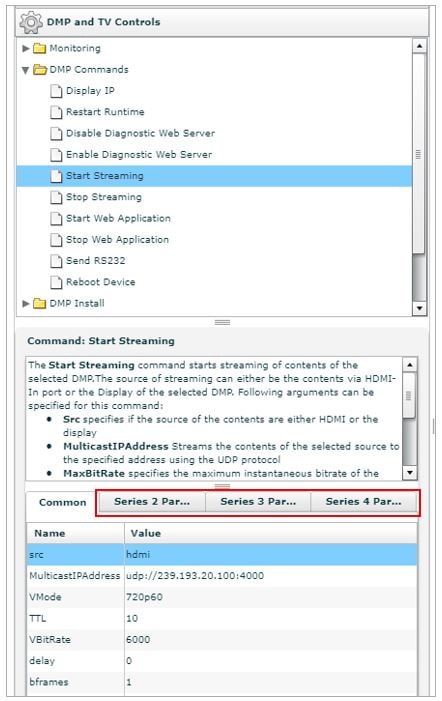
Starting and Stopping Streaming by Management Dashboard Command
To start and stop streaming in the Management Dashboard:
1.![]() Click More > Management Dashboard > DMP and TV Controls > DMP Commands > Start Streaming .
Click More > Management Dashboard > DMP and TV Controls > DMP Commands > Start Streaming .
2.![]() Configure the DMP-encoded channel options in the DMP Parameters (Figure 25).
Configure the DMP-encoded channel options in the DMP Parameters (Figure 25).
Figure 25 Start/Stop Streaming Commands in Management Dashboard
3.![]() Select the device where you want to start HDMI-In streaming.
Select the device where you want to start HDMI-In streaming.
4.![]() Click the Play icon to execute the command.
Click the Play icon to execute the command.
5.![]() From the Management Dashboard console, verify that the Start Streaming command is successful.
From the Management Dashboard console, verify that the Start Streaming command is successful.
HDMI-In Streaming Versus Display Streaming
For HDMI-In streaming, what streams from the DMP is the audio/video from the HDMI-In port source ONLY (Figure 26).
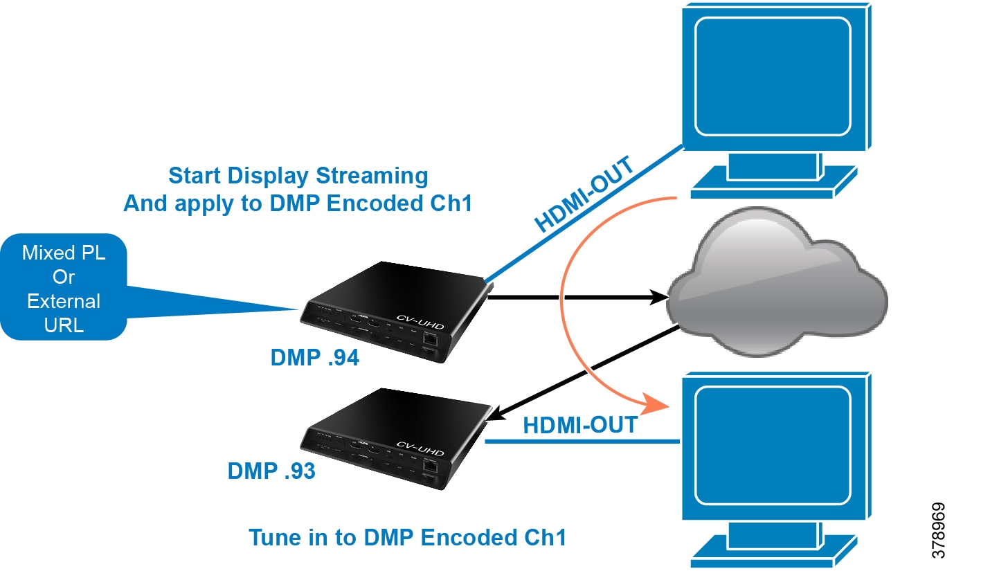
For Display Streaming, entire video composition (without audio) will be streamed from the DMP - i.e., an encoded rendition of what you see on the TV connected to the DMPs HDMI-out.
Display streaming can be used even when your video source is not HDMI-In, or in cases where you want to encode/stream not just HDMI-In but also other elements on the screen, or maybe an HTML5 page (you don't need a video source in display streaming). Display streaming parameters are set in channels where the DMP is the encoder (DMP encoded channels).
HDMI-In Streaming
Local HDMI-In (HDMI-In Pass-Through for SV-4K, CV-UHD, and CV-UHD2 Players)
Note: The following sections show an example of how to set HDMI-In streaming.
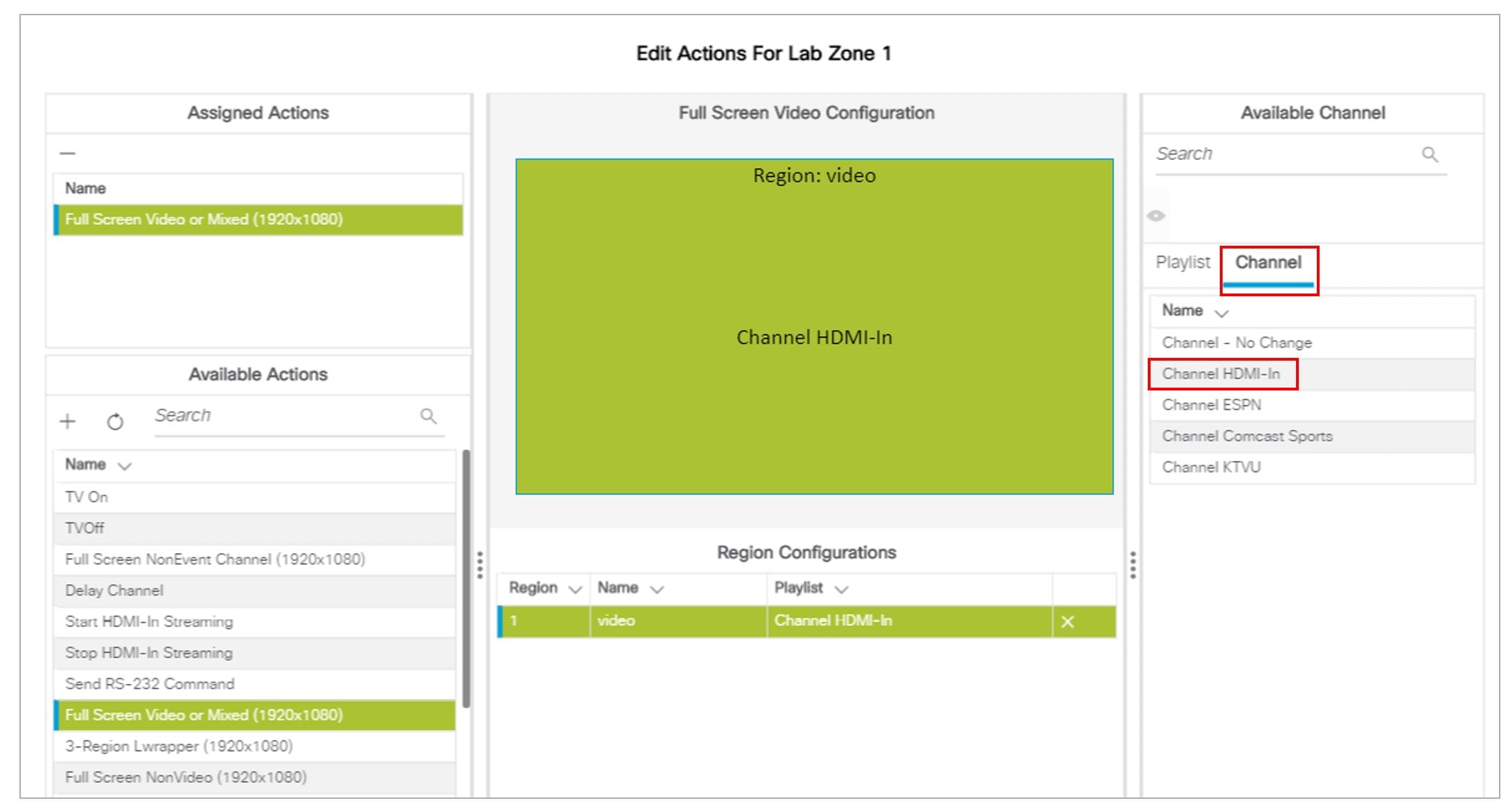
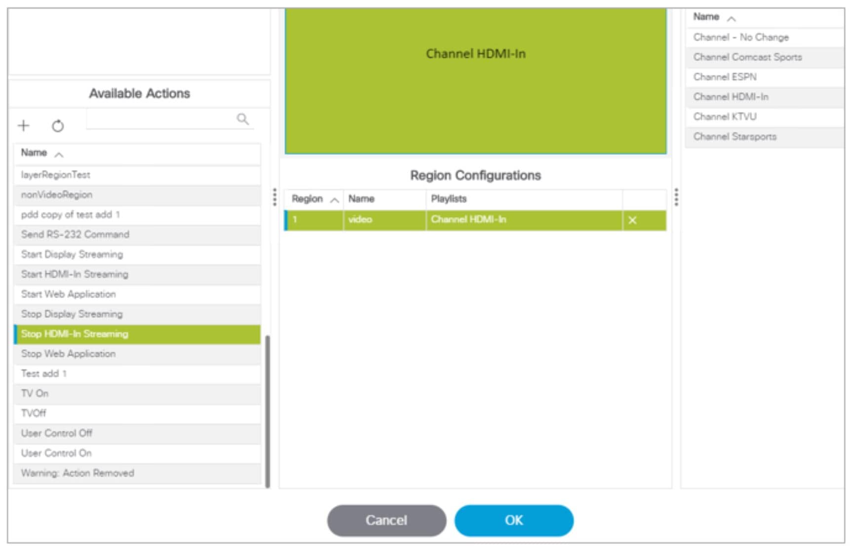
Script Configuration
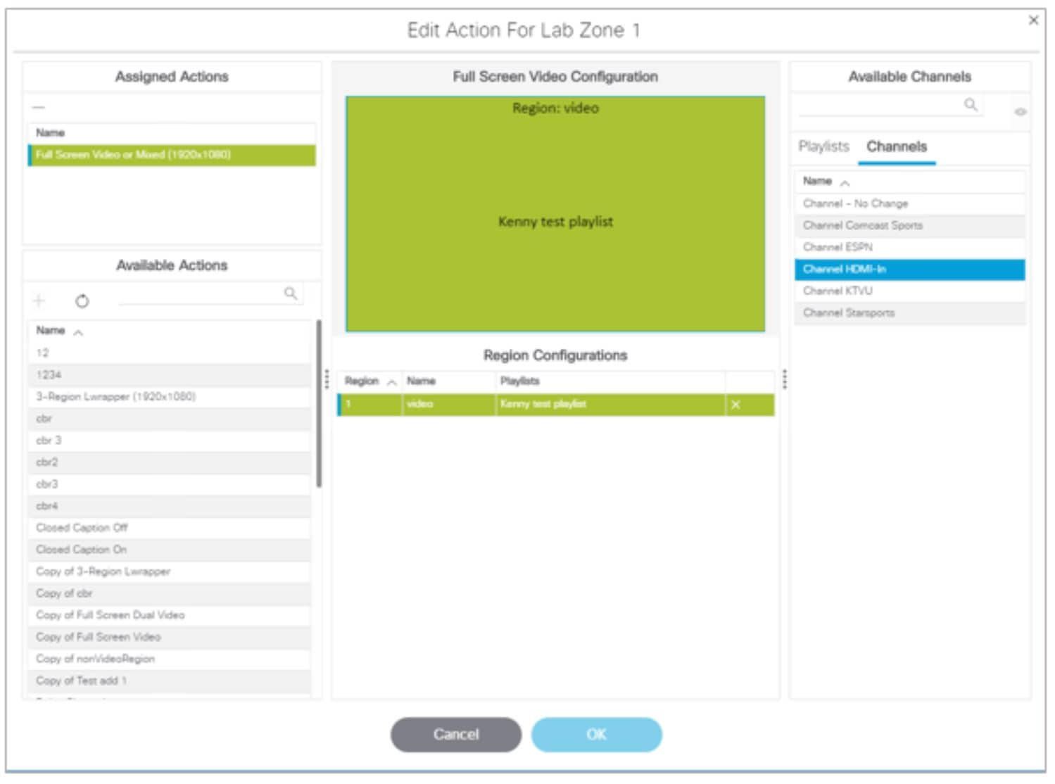
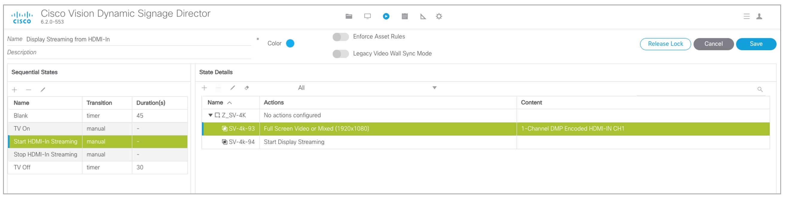
1.![]() Assign for DMP.94 pre-defined Channel 0 “Channel HDMI-In” to action Full Screen Video or Mixed (1920X1080).
Assign for DMP.94 pre-defined Channel 0 “Channel HDMI-In” to action Full Screen Video or Mixed (1920X1080).
When script runs, all input from HDMI-In will be streamed out to the Display via HDMI-OUT (Figure 27).
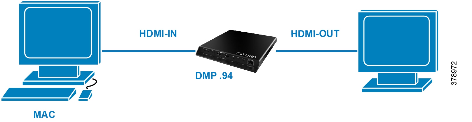
Figure 27 Full Screen Video Streaming
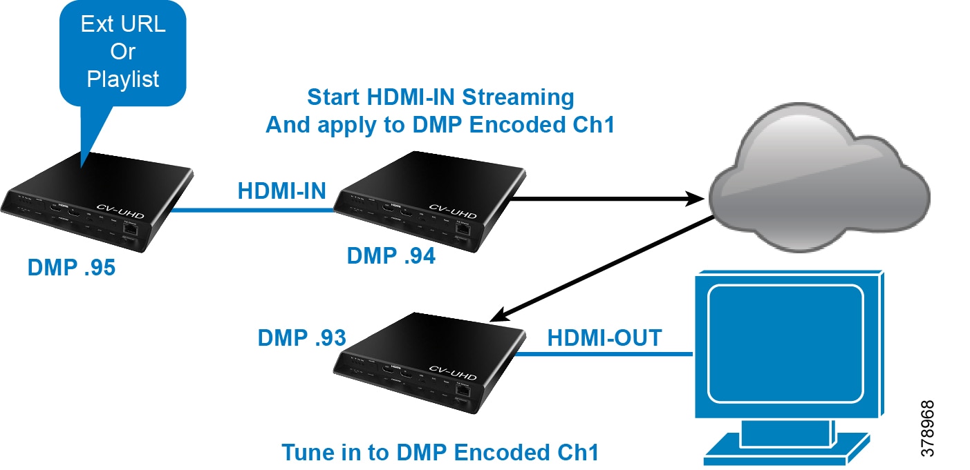
DMP HDMI-In Streaming
Script Configuration
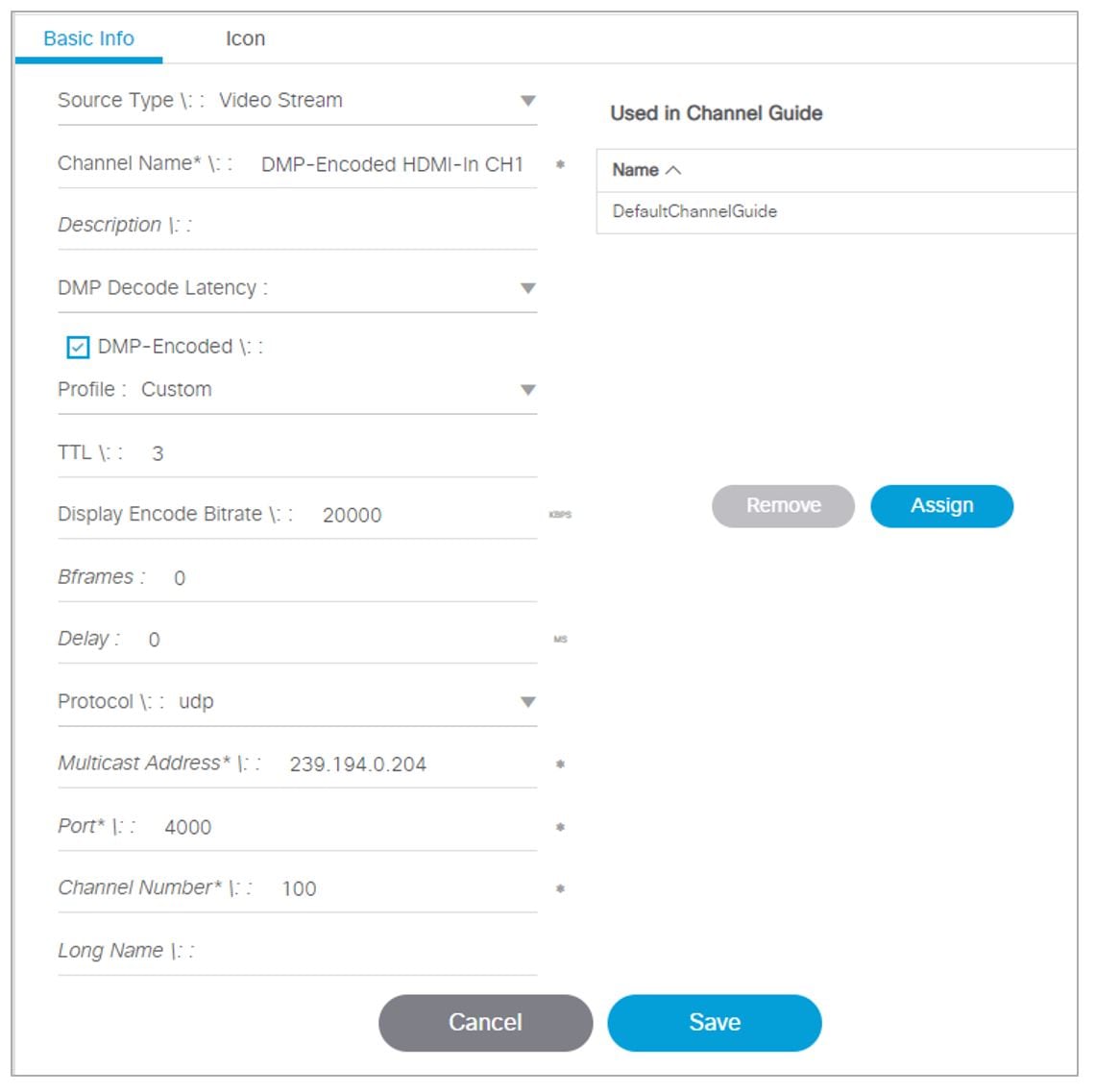
1.![]() Create DMP-encoded CH1 configuration (Figure 28). Go to Configuration > Channel Definitions > Master Channel List tab > Basic Info tab.
Create DMP-encoded CH1 configuration (Figure 28). Go to Configuration > Channel Definitions > Master Channel List tab > Basic Info tab.
Figure 28 Create DMP-Encoded Channel 1
2.![]() Attach video source to HDMI-IN.
Attach video source to HDMI-IN.
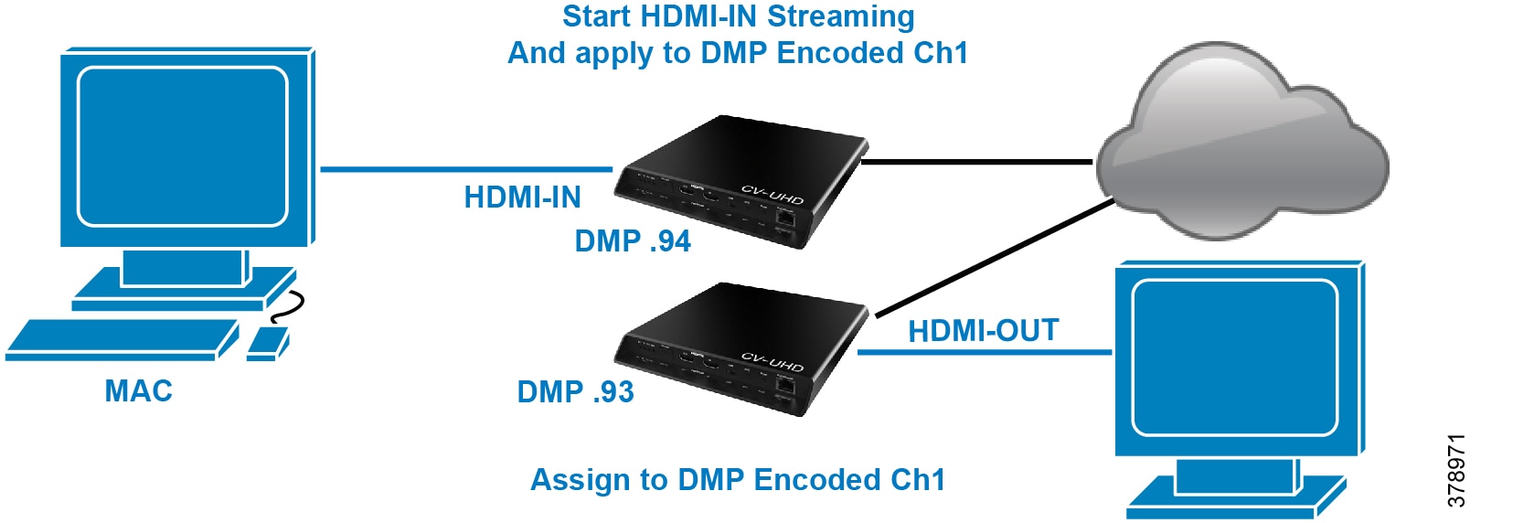
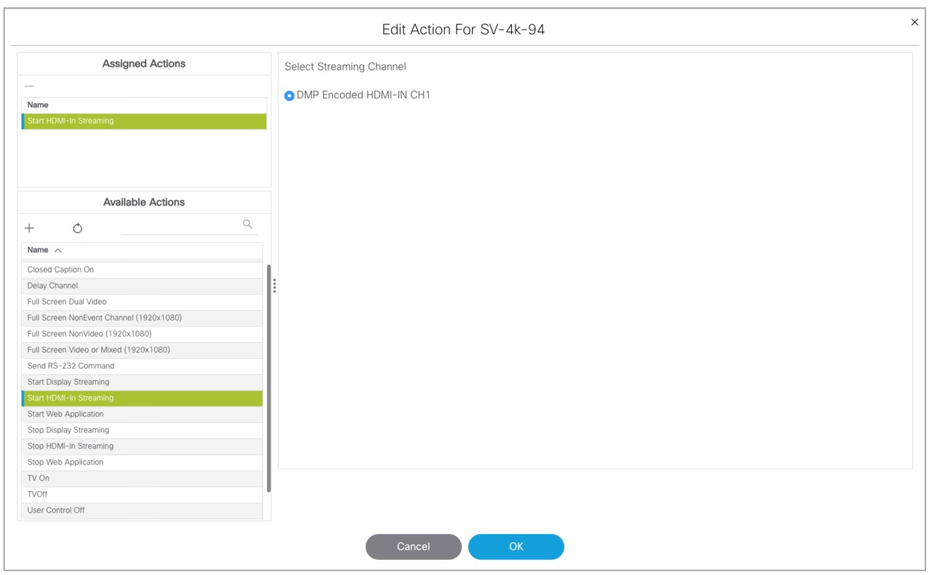
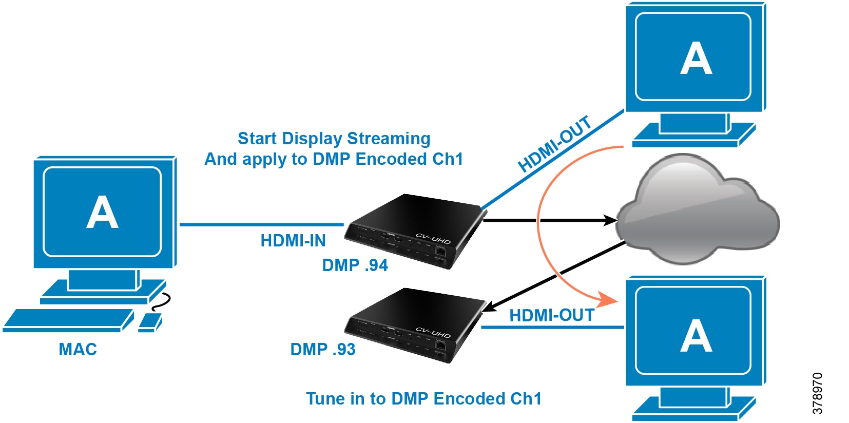
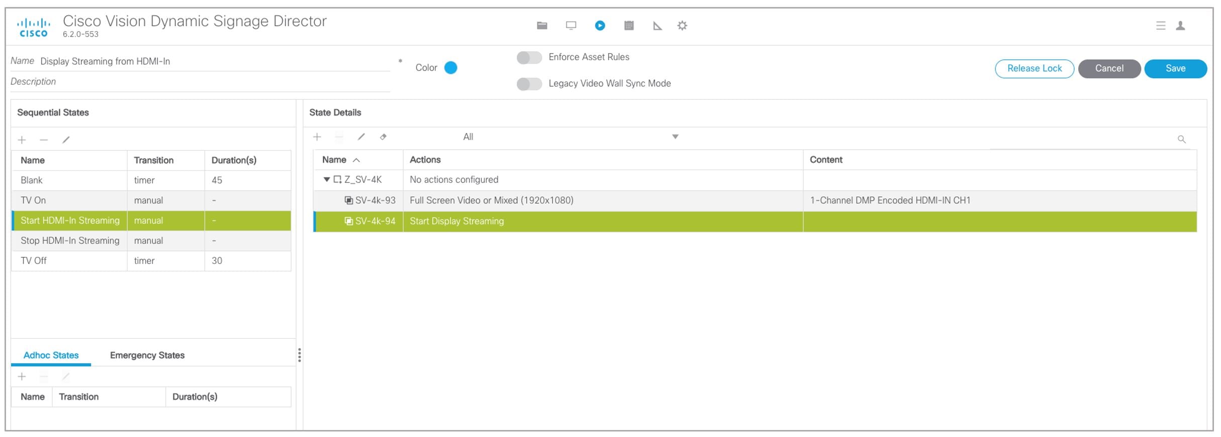
3.![]() For DMP.94 (Figure 29): Script action Start HDMI-In Streaming and assign it to DMP encoded channel 1.
For DMP.94 (Figure 29): Script action Start HDMI-In Streaming and assign it to DMP encoded channel 1.
4.![]() For DMP.93: Tune in on DMP Encoded channel 1 (Figure 30).
For DMP.93: Tune in on DMP Encoded channel 1 (Figure 30).
Figure 29 Start HDMI-In Streaming to DMP-Encoded Channel 1
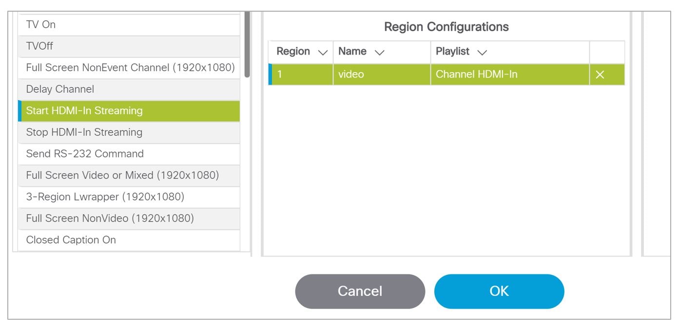
Figure 30 DMP-Encoded Channel 1
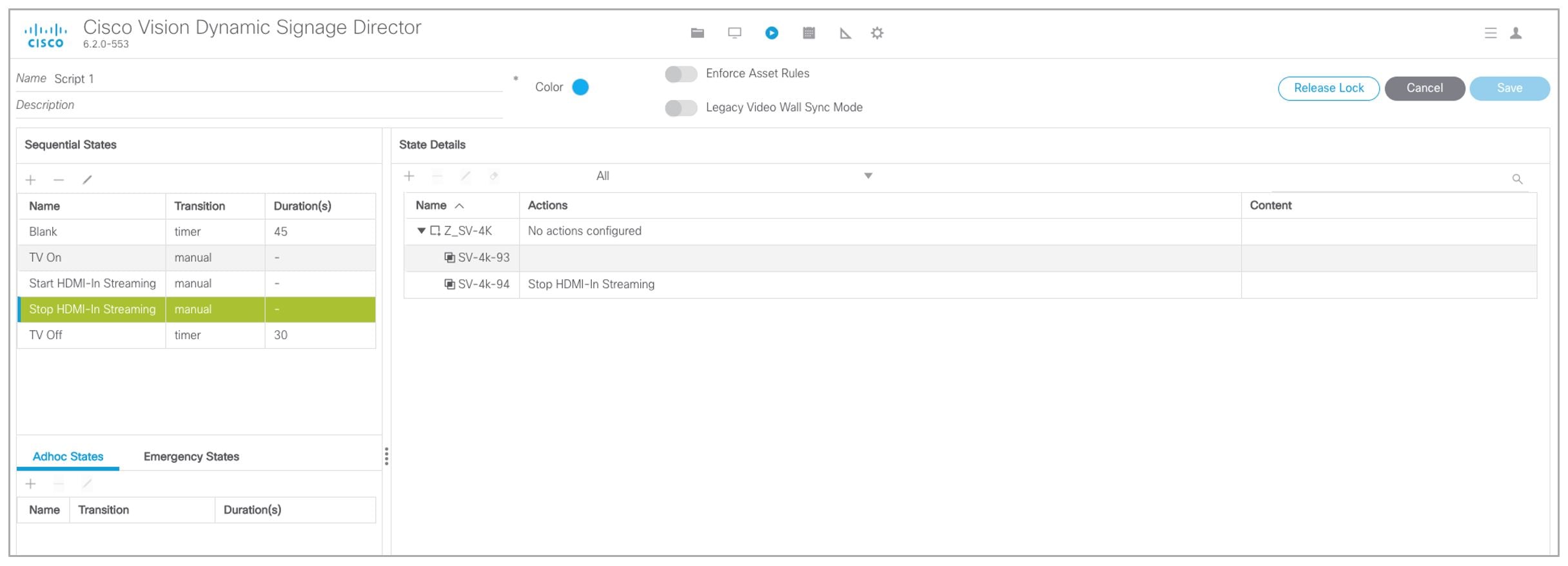
5.![]() On DMP.94: stop display streaming (Figure 31). See Configuring HDMI-In as a Video Source in a Region on the SV-4K, CV-UHD, and CV-UHD2 Media Players.
On DMP.94: stop display streaming (Figure 31). See Configuring HDMI-In as a Video Source in a Region on the SV-4K, CV-UHD, and CV-UHD2 Media Players.
Figure 31 Stop HDMI-In Streaming
HDMI-In Streaming with External URL Source or Playlist
When you want to use the DMP HDMI-IN encoder to broadcast an External URL Script or a Playlist, there is an additional head-end DMP required (DMP.95).
Script Configuration
1.![]() Create separate script and run Ex. Mixed playlist on DMP.95.
Create separate script and run Ex. Mixed playlist on DMP.95.
2.![]() Connect the HDMI-OUT to the HDMI-IN of DMP.94 (Figure 32).
Connect the HDMI-OUT to the HDMI-IN of DMP.94 (Figure 32).
Figure 32 Start HDMI-In Streaming and Assign to DMP-Encoded Channel
3.![]() In DMP.94 Start HDMI-Streaming and assign to DMP encoded Channel.
In DMP.94 Start HDMI-Streaming and assign to DMP encoded Channel.
4.![]() DMP.93: Select DMP Encoded channel 1.
DMP.93: Select DMP Encoded channel 1.
5.![]() On DMP.94, stop display streaming (Figure 33).
On DMP.94, stop display streaming (Figure 33).
Figure 33 Stop HDMI-In Streaming on DMP 94
Display Streaming
Display Streaming with Video Source Input on DMP HDMI-In
In this scenario, everything entering the HDMI-IN is displayed on the TV connected to the encoder DMP (DMP.94) and will be streamed out on DMP channel Encoded Ch1.
Script Configuration
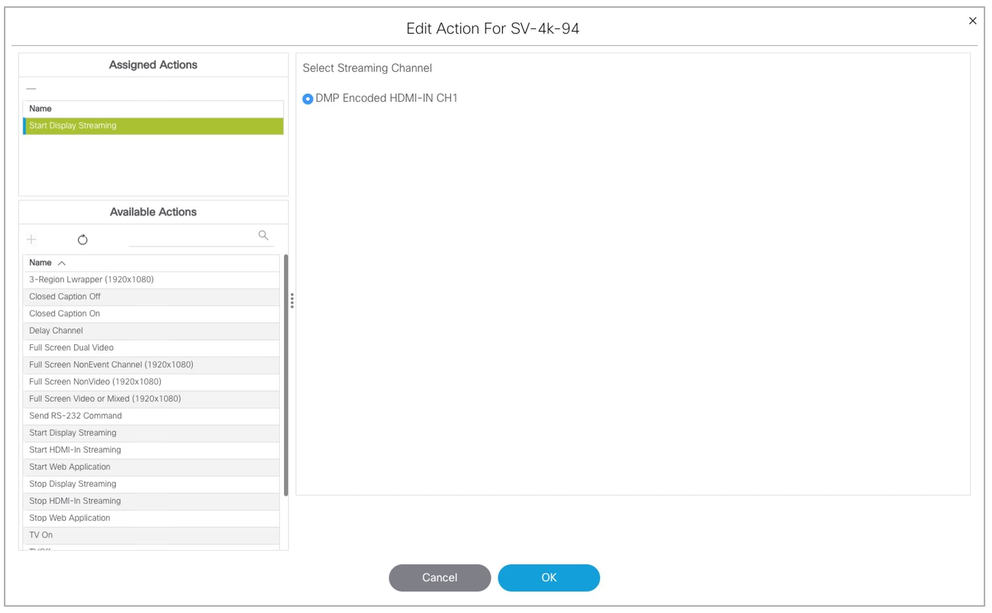
1.![]() In DMP.94, start display streaming (Figure 34) and assign to DMP encoded Channel 1 (Figure 35).
In DMP.94, start display streaming (Figure 34) and assign to DMP encoded Channel 1 (Figure 35).
Figure 34 Start Display Streaming on DMP.94
IMPORTANT: When content rules are in place, a DMP that reboots may not display the same content as other DMPs in the same group until the next state change.
Figure 35 Select Streaming Channel
2.![]() For DMP.93, tune to DMP-encoded Channel 1 (Figure 36).
For DMP.93, tune to DMP-encoded Channel 1 (Figure 36).
Figure 36 Start Display Streaming on DMP.93
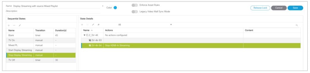
Display Streaming with External URL or Mixed Media Playlist
In this scenario, no HDMI-IN of the DMP is used. A script in DMP 94 is setup and started. Once the script runs, “Start Display Streaming” will attach it to the DMP-encoded channel, functioning as a multicast channel.
Script Configuration
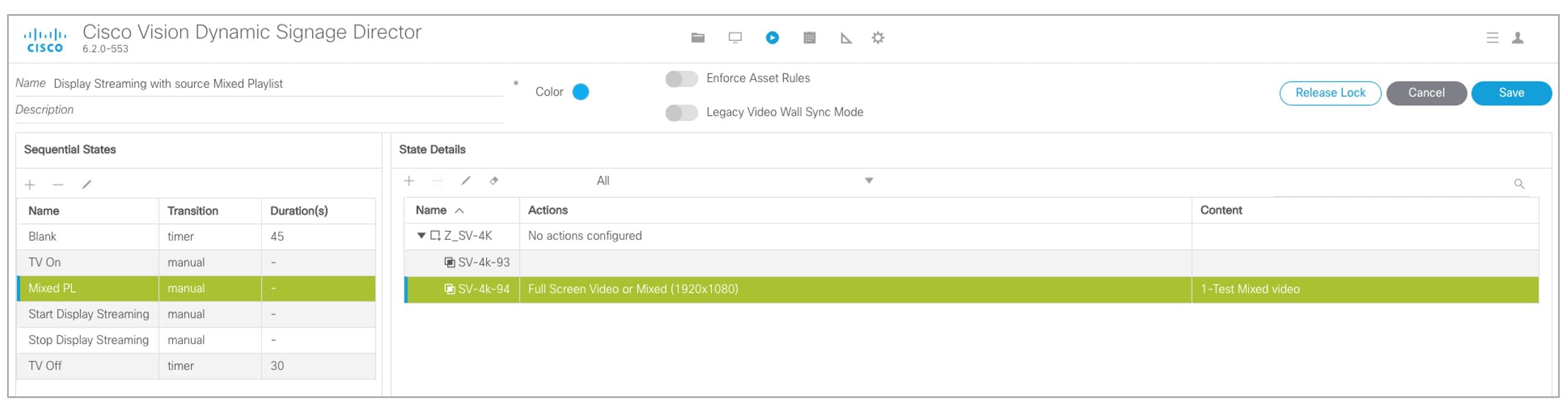
2.![]() Choose event state “Mixed PL.”
Choose event state “Mixed PL.”
3.![]() Assign “Full Screen Video or Mixed (1920X1080)” to DMP.94 (Figure 37).
Assign “Full Screen Video or Mixed (1920X1080)” to DMP.94 (Figure 37).
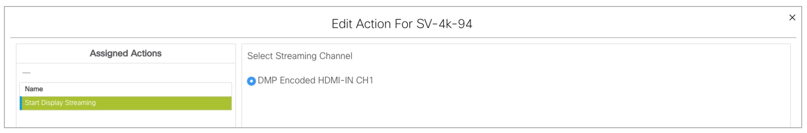
4.![]() For DMP.94, Start Display Streaming (Figure 38) and assign it to DMP-encoded Channel 1 (Figure 39).
For DMP.94, Start Display Streaming (Figure 38) and assign it to DMP-encoded Channel 1 (Figure 39).
Figure 38 Start Display Streaming on DMP.94
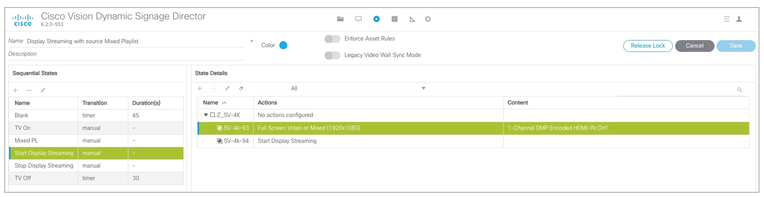
Figure 39 Select Streaming Channel
On DMP.93, choose the DMP-encoded channel 1 (Figure 40).
Figure 40 Assign DMP.93 to Channel DMP Encoded HDMI-In Channel 1
On DMP.94, Stop HDMI-In Streaming (Figure 41).
Figure 41 Stop HDMI-In Streaming on DMP.94
How to Manage Content (Assets)
This section includes the following topics:
■![]() Getting Content Into Cisco Vision Director
Getting Content Into Cisco Vision Director
■![]() Staging Content to the Media Player
Staging Content to the Media Player
Library (Content) Screen
The Library (content/assets) screen allows you to both manage content as well as create and modify playlists.
Library Inbox
New in Release 6.2 is Inbox allowing you to schedule import of assets from external sources, accessible via secure file transfer protocols (SFTP). The assets available at the external sources are checked for valid extensions and file size as configured in Director. (Figure 42). If you don’t specify a destination folder in the Asset Library, the assets are downloaded to the Site list in Inbox, where they can be reviewed and moved to Workspace folders, appropriately.
Figure 42 Library, Inbox for Automated Importing of Assets
To create an automated content import event:
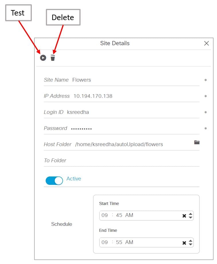
1.![]() Click New Site. The Create Site window appears (Figure 43).
Click New Site. The Create Site window appears (Figure 43).
2.![]() Fill in the fields. The fields marked with * are required.
Fill in the fields. The fields marked with * are required.
3.![]() Schedule Start Time and End Time.
Schedule Start Time and End Time.
Figure 43 Create New Content Source Site
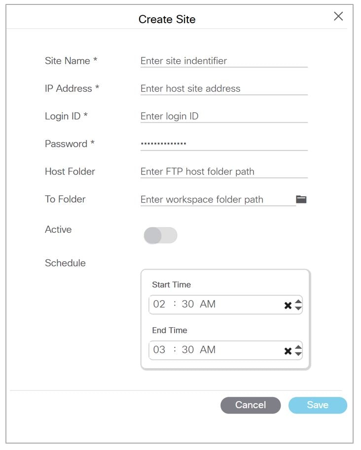
4.![]() (Optional) Choose the Host folder and the To Folder.
(Optional) Choose the Host folder and the To Folder.
To test the content source for validity:
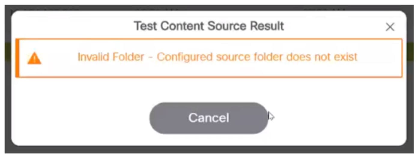
1.![]() Click the Test icon (Figure 44). Test checks the connectivity, validity of the credentials supplied, and also the existence of the configured source folder of the configured site.
Click the Test icon (Figure 44). Test checks the connectivity, validity of the credentials supplied, and also the existence of the configured source folder of the configured site.
Figure 44 Test and Delete a Content Source
If you entered any invalid information, you will see a failure notice. In the case below, it is an invalid destination folder.
If you do not choose a destination folder in the Create Site dialog box, you can preview the content and decide if you want to download it. The unspecified content shows in the Inbox list.
To preview unspecified automated content from the Inbox list:
1.![]() Select the content from the Inbox list in the center panel and double click it (Figure 45).
Select the content from the Inbox list in the center panel and double click it (Figure 45).
2.![]() Click the Play icon in the Site Details right panel to preview the content or change the center panel to thumbnail view.
Click the Play icon in the Site Details right panel to preview the content or change the center panel to thumbnail view.
To download unspecified automated content from the Inbox list to Cisco Vision Director:
1.![]() Select the content from the Inbox list in the center panel and right click it. An Action box appears (Figure 45).
Select the content from the Inbox list in the center panel and right click it. An Action box appears (Figure 45).
Figure 45 Action Box Operations for Auto-Content Import
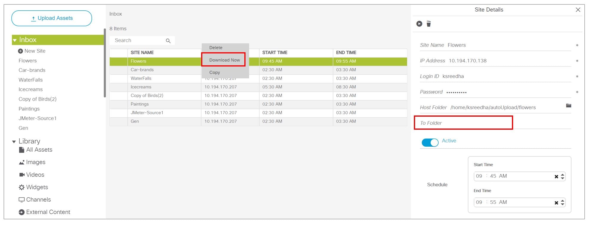
If successful, you see “Content Import successfully triggered now.” This action triggers the content import On Demand. Since you didn’t choose a destination folder, the content goes to the Workspace Folder.
If you mapped the automated content to a designated folder in the Site Details panel, once the Download Now command is executed or the scheduled Start Time has passed, if you click on that content in Inbox, you see:

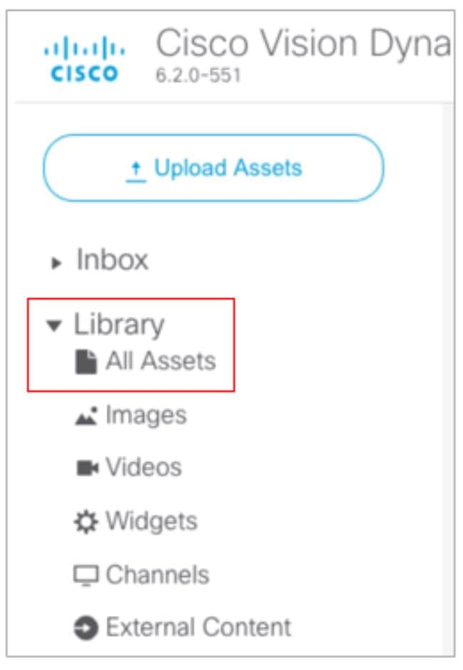
Use the Library menu to do the following tasks:
■![]() Import static graphics or local video content.
Import static graphics or local video content.
■![]() Add an HTML pass-through URL.
Add an HTML pass-through URL.
–![]() Sort the content by name, type, URL, size, or expiration date.
Sort the content by name, type, URL, size, or expiration date.
Library Screen Views
The Content screen has three views:
■![]() Library View (default)
Library View (default)
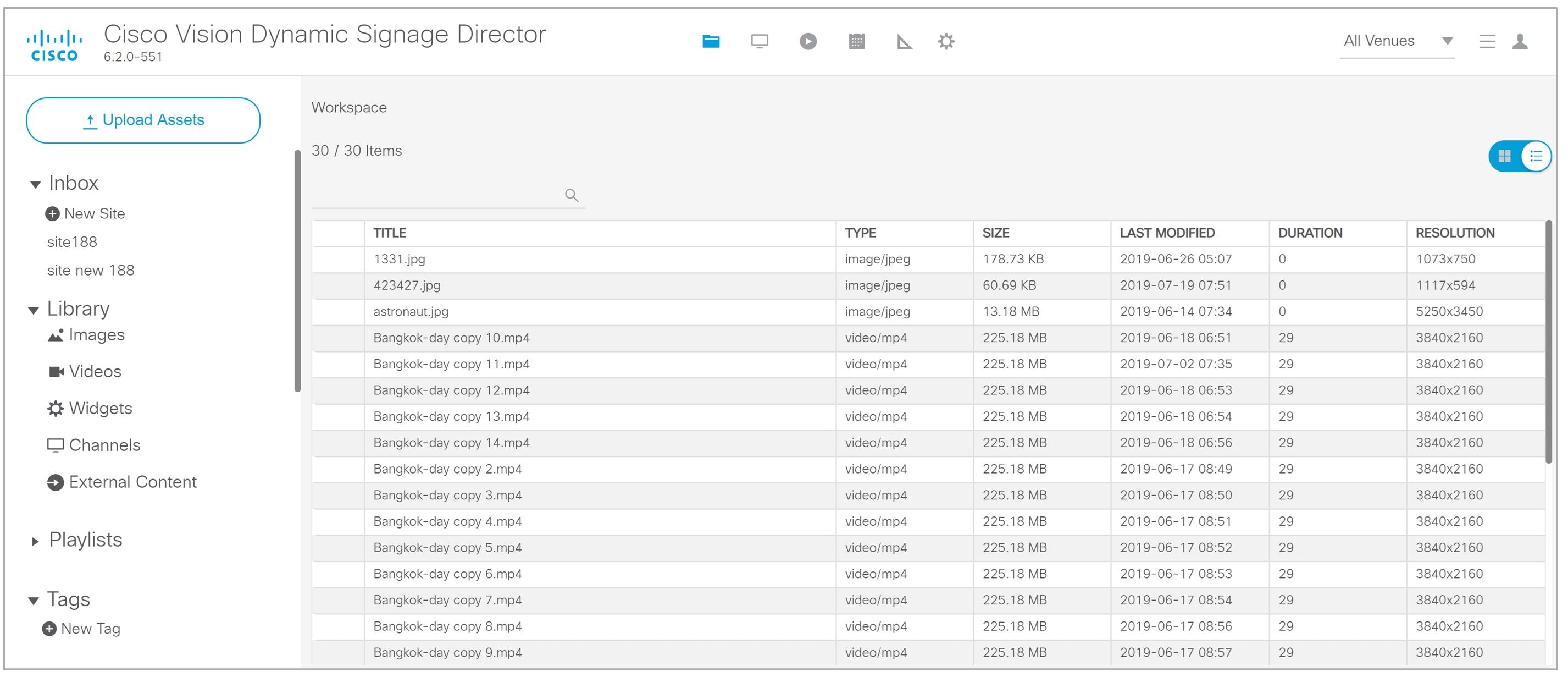
Library View
Library View (Figure 42) identifies the content-related layout and task options available from the Library.
Asset Items Panel
Asset items display as a list with details or as thumbnails. Use the slider in blue in the top right to change views.
By default, the Library Assets window shows List View of the following items stored in the Library:
■![]() All Assets (when multi-venue is not enabled)
All Assets (when multi-venue is not enabled)
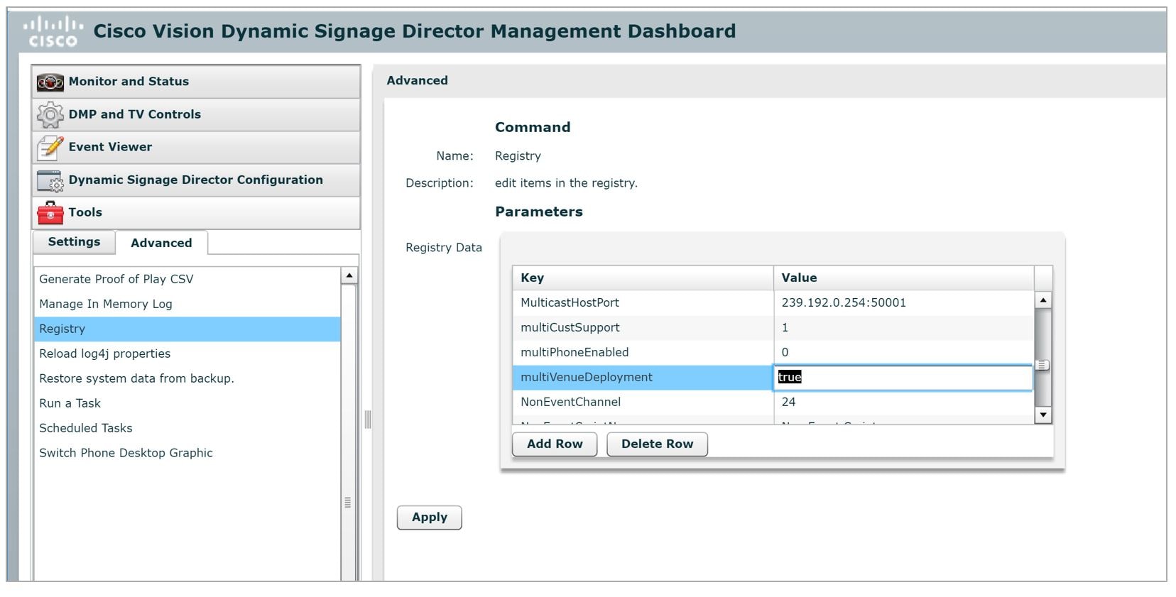
Note : In the left panel of the Library interface, the Library drop-down menu shows All Assets only when the registry setting for multiVenueDeployment is set to false. If multiVenueDeployment is set to true, All Assets is not visible.
To allow all assets across multi-venues:
1.![]() Go to More > Management Dashboard > Tools drawer > Advanced tab > Registry.
Go to More > Management Dashboard > Tools drawer > Advanced tab > Registry.
2.![]() In Registry Data, scroll to multiVenueDeployment. Set the Value to true (Figure 46).
In Registry Data, scroll to multiVenueDeployment. Set the Value to true (Figure 46).
Figure 46 Registry for Multi-Venue Deployment
Playlist View
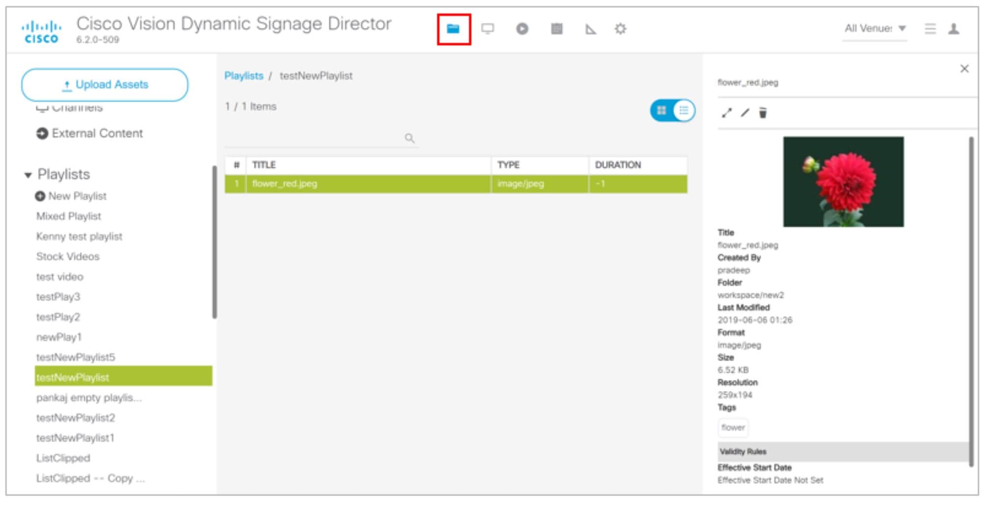
1.![]() Click Playlist in the Library window to display your available playlists. The screen shows List View and gives the Title, Type, and Duration of your content.
Click Playlist in the Library window to display your available playlists. The screen shows List View and gives the Title, Type, and Duration of your content.
2.![]() Click any row to get the details of any content selected (Figure 47).
Click any row to get the details of any content selected (Figure 47).
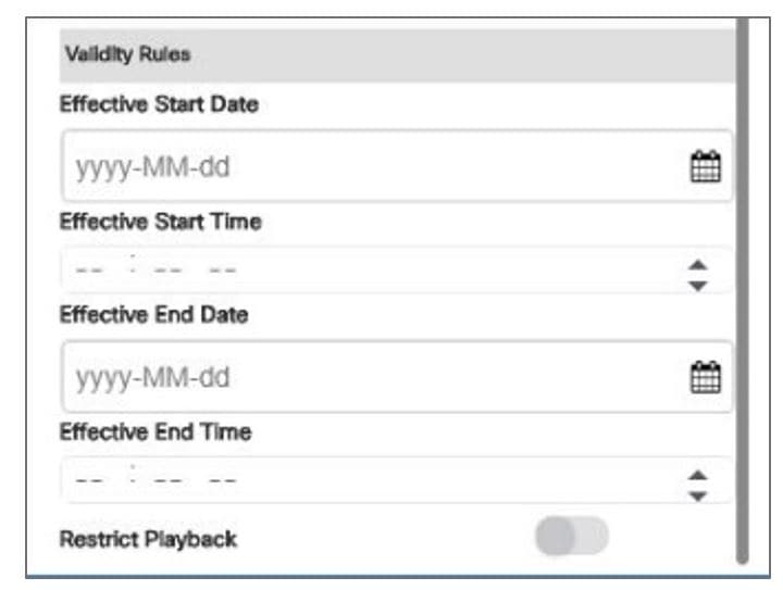
3.![]() Use the pen icon to edit information for your content. The Validity Rules panel appears (Figure 48).
Use the pen icon to edit information for your content. The Validity Rules panel appears (Figure 48).
4.![]() Set the Effective Start and End Dates and Times. Click the calendar icon.
Set the Effective Start and End Dates and Times. Click the calendar icon.
5.![]() You can also choose Restrict Playback here. Set the days and times specifically as to when your content will not display.
You can also choose Restrict Playback here. Set the days and times specifically as to when your content will not display.
6.![]() Click the Save icon in the top of the panel.
Click the Save icon in the top of the panel.
Figure 48 Validity Rules Panel
Asset (Content) Validation
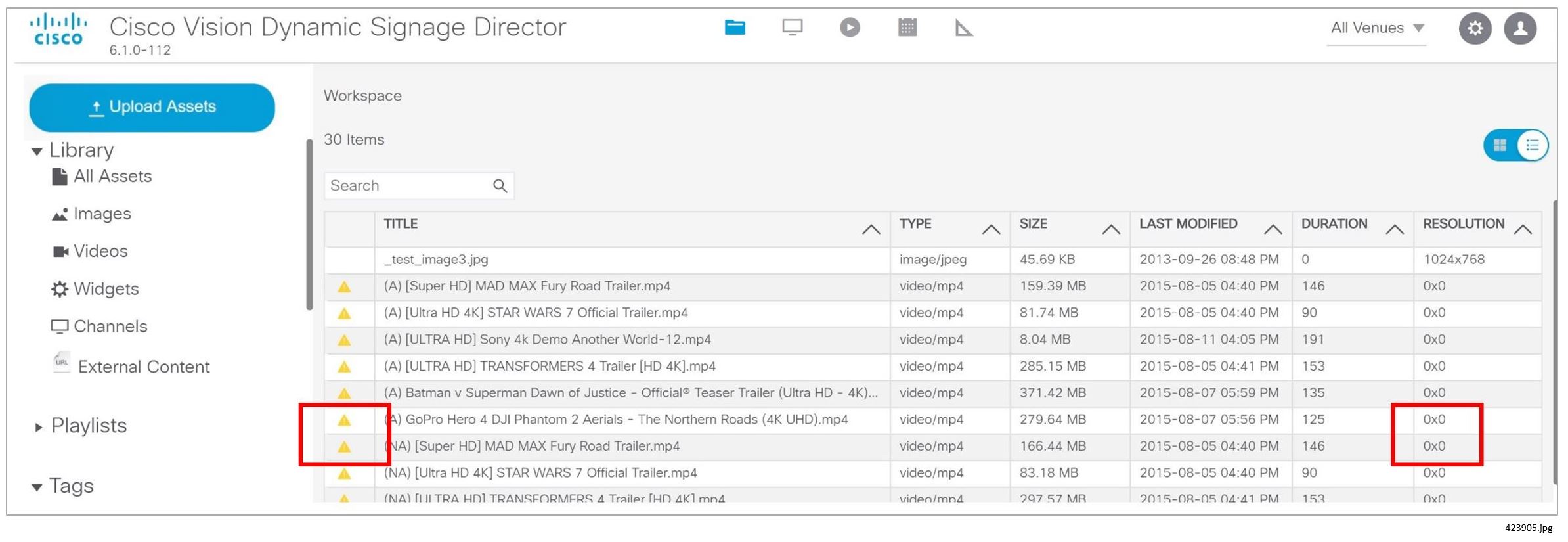
If you upload a piece of content that is not supported by the DMP (Figure 49), you get a warning message. The warning symbols means that the content may be distorted on the display. Best practice is to correct any warnings of your content so it will appear as planned. Hover over the icon for information.
The warning displays if the content metadata does not meet the restrictions defined in Management Dashboard. These settings do not necessarily mean that the DMP does not support the content, but it can be configured that way. As an example, if a site has content guidelines that all images must be no more than 1920x1080 only, and videos must be no more than full HD resolution only, that can be set in Management Dashboard. UHD video files can be played on the UHD DMPs, but a warning may still show in the UI.
Figure 49 Warning Symbol for Content Validity
To check the validity of content:
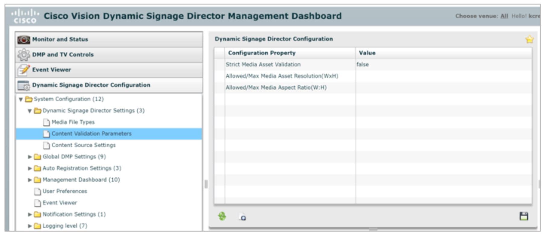
1.![]() Go to More > Management Dashboard > Dynamic Signage Configuration > System Configuration > Dynamic Signage Director Settings > Content Validation Parameters.
Go to More > Management Dashboard > Dynamic Signage Configuration > System Configuration > Dynamic Signage Director Settings > Content Validation Parameters.
Note : Since you can upload images and videos, each type has different issues involved in troubleshooting them. For images and videos, clear the warning here.
2.![]() Check the resolution parameters of your assets to be certain they fall within the ranges allowed (Figure 50).
Check the resolution parameters of your assets to be certain they fall within the ranges allowed (Figure 50).
Figure 50 Management Dashboard Content Validation Parameters
Asset Search Methods
Use the Playlist screen to find your asset items or playlists in multiple ways:
■![]() Search for asset items assigned with a particular tag name by selecting the tag in the Library left pane.
Search for asset items assigned with a particular tag name by selecting the tag in the Library left pane.
■![]() Search for asset items by name or file type using the Search box on the Playlist panel.
Search for asset items by name or file type using the Search box on the Playlist panel.
TIP: You can enter the first few letters of the content file name, or enter a file type such as ".jpg" in the search box.
■![]() Search for playlists using the Search box on the Playlist panel, and by typing in the first few letters of the playlist name.
Search for playlists using the Search box on the Playlist panel, and by typing in the first few letters of the playlist name.
Guidelines for Asset Tags
Consider the following guidelines to create asset tags:
■![]() Proof of Play processing requires the following naming convention:
Proof of Play processing requires the following naming convention:
■![]() <tag name> _PoP
<tag name> _PoP
where <tag name> is the name for your proof of play label, and the “_PoP” suffix is required to designate the label for proof of play processing.
■![]() The following characters are not supported in tag names: / ? < > \ : * | "
The following characters are not supported in tag names: / ? < > \ : * | "
■![]() Content in multiple playlists can use the same tag. The number of playlists that have content assigned to a tag displays under the # column in the Playlist Detail window next to the tag name.
Content in multiple playlists can use the same tag. The number of playlists that have content assigned to a tag displays under the # column in the Playlist Detail window next to the tag name.
Creating and Assigning Content Tags
User Role: Administrator / Content Manager
TIP: Consider assigning zone and group names as tags for the content files used in those areas. This allows you to type in a single search word or phrase and find all the content for a given zone or group, such as “Luxury Suite Delta” or “Concourse A.” You can also use tags that correspond to the type of content in the playlist, such as “menu.”
To create and assign content tags:
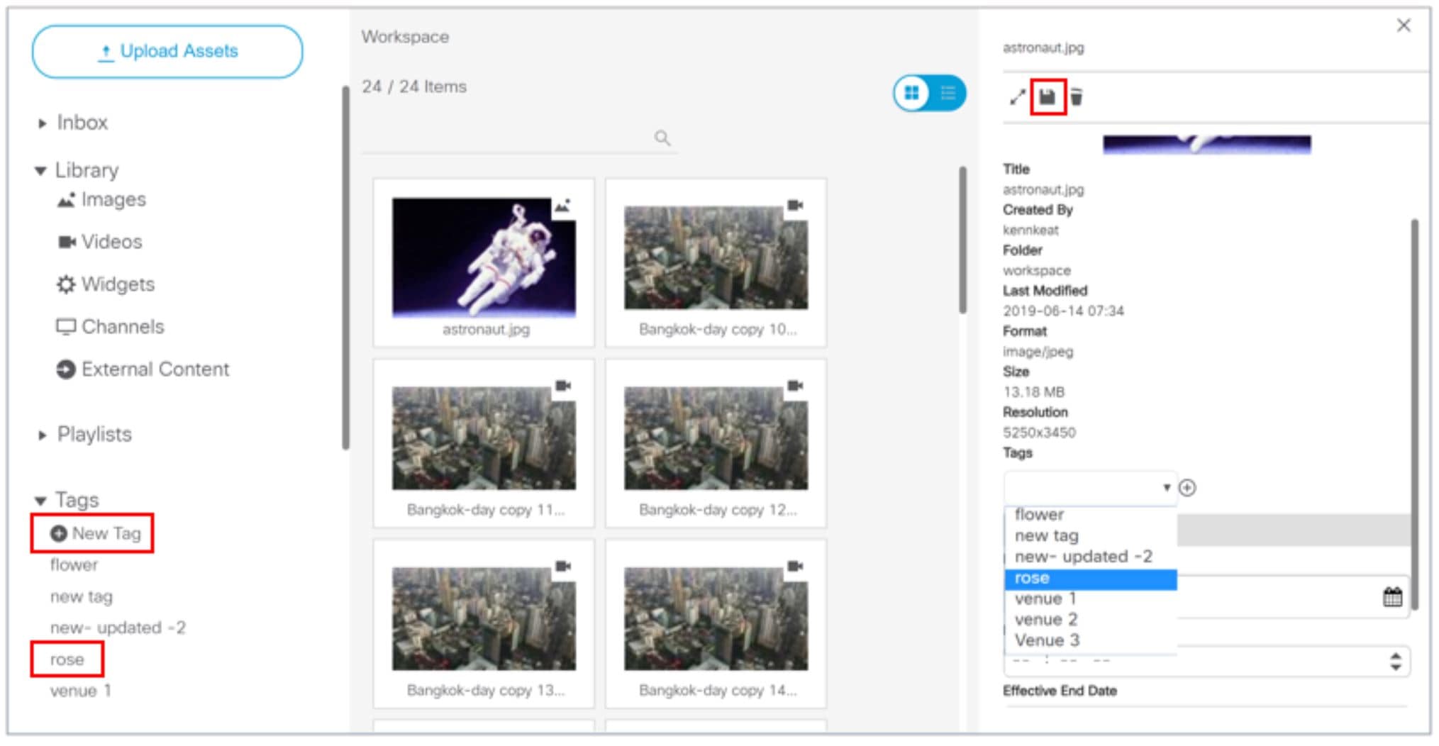
1.![]() Click Library > Tag arrow. New Tag appears.
Click Library > Tag arrow. New Tag appears.
3.![]() In the field, type a new name for the tag.
In the field, type a new name for the tag.
4.![]() Hit Return/Enter. The tag name appears.
Hit Return/Enter. The tag name appears.
IMPORTANT: The following characters are not supported in tag names: / ? < > \ : * | ".
Note : If the tag name doesn’t appear, click Refresh.
Be sure to include the required “_PoP” suffix in your tag name for proof of play records. For more information about Proof of Play, see the Cisco Vision Director Proof of Play.
5.![]() To assign a tag to content, select the content (asset) from the Grid or List view. The detail pane appears ( Figure 51).
To assign a tag to content, select the content (asset) from the Grid or List view. The detail pane appears ( Figure 51).
6.![]() Click the Pen icon to edit the metadata.
Click the Pen icon to edit the metadata.
7.![]() Select the tag name you want to attach to your content.
Select the tag name you want to attach to your content.
Figure 51 Assigning a Tag to Content
TIP : Assign tags to content when you first upload content to the Library.
9.![]() To verify that the content was assigned to the tag, click the tag name. The content assigned to the selected tag will display in the Content Items area.
To verify that the content was assigned to the tag, click the tag name. The content assigned to the selected tag will display in the Content Items area.
Removing a Tag From Content
User Role: Administrator / Content Manager
When you remove a tag from content, the content will no longer be associated with that tag but the content itself remains in the Asset Library. Figure 52 summarizes the steps to remove a tag from selected content.
Figure 52 Workflow Summary to Remove a Tag From Content
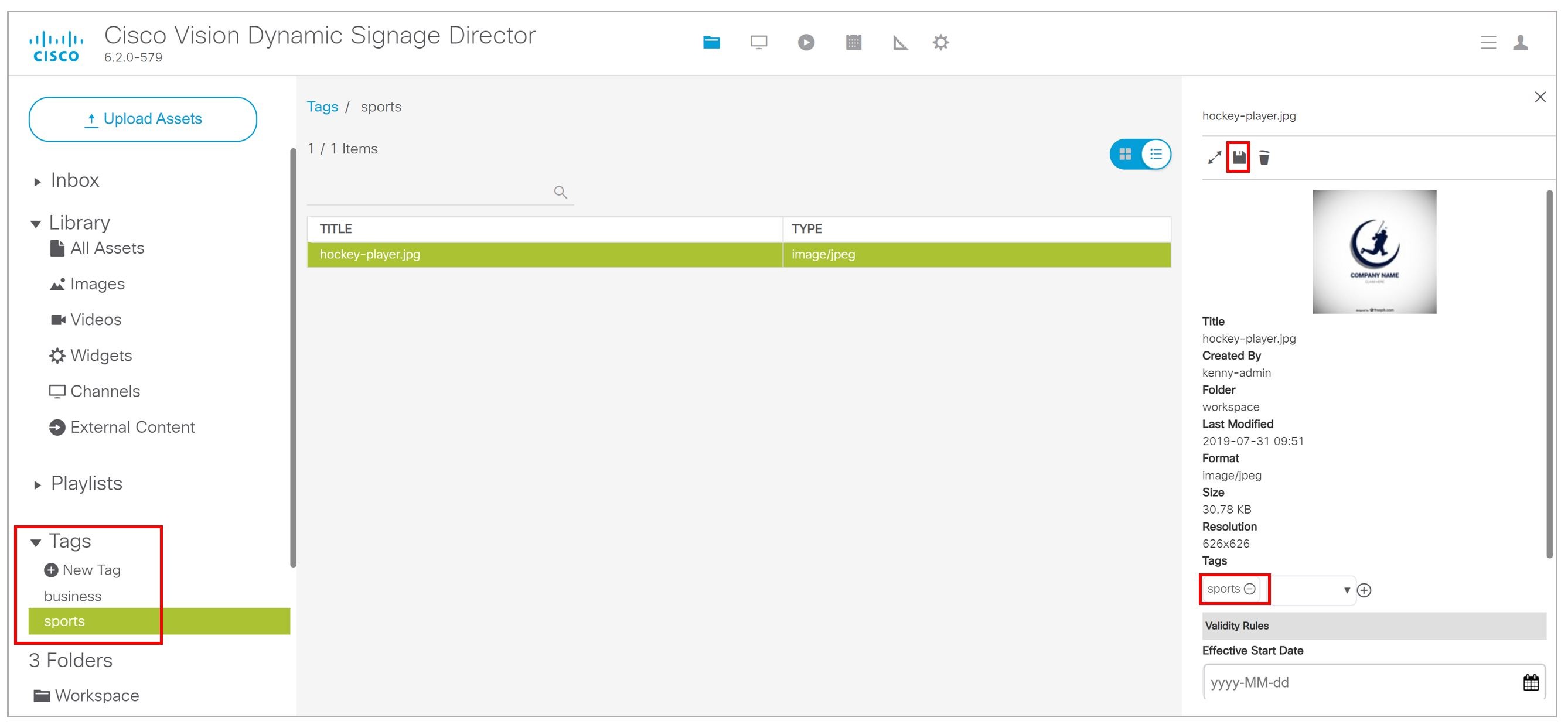
1.![]() In Library, select the tag name. The content items for that tag display in the Tags panel.
In Library, select the tag name. The content items for that tag display in the Tags panel.
2.![]() Click on the content item from which you want to remove the tag.
Click on the content item from which you want to remove the tag.
TIP: Use the keyboard Shift-Click function to select and untag multiple content items assigned to a tag.
3.![]() Click the Pen icon in the Detail Panel to edit the tag metadata. The Tag information appears.
Click the Pen icon in the Detail Panel to edit the tag metadata. The Tag information appears.
4.![]() Click the tag name and the “–” symbol to remove the tag from the asset.
Click the tag name and the “–” symbol to remove the tag from the asset.
There is no confirmation prompt. The tag is immediately removed from the content.
Getting Content Into Cisco Vision Director
Cisco Vision Director supports a wide variety of content types and methods for ingesting content.
There are limitations and specifications for the content size and formats supported by Cisco Vision Director. These vary depending upon a number of factors including the TV display resolution, the media player used in the venue, the screen template region layout, and the TV proximity to the fans.
Before you deploy content to Cisco Vision Director, be sure that you refer to the Cisco Vision Content Planning and Specification Guide, Dynamic Signage Director, Release 6.2 to be sure the content is in the correct format, is the appropriate size, and has the correct dimensions for where it will be displayed. If the content is not the correct size for the region into which it will be placed, the image will either be cropped or there will be blank space in the region.
Table 4 summarizes the different content types supported by Cisco Vision Director, the methods of how you ingest the content, and references to topics in this document and other external guides where you can find the details about how to work with that content type.
Table 4 Content Ingestion Methods by Type of Content
|
|
|
|
|---|---|---|
|
|
|
|
|
|
|
|
|
|
|
|
|
|
|
|
|
|
|
|
|
|
|
|
|
|
|
|
|
|
|
|
|
|
|
|
|
|
|
|
|
|
|
|
|
|
|
|
|
|
|
|
|
|
|
|
|
|
|
|
|
|
|
|
|
|
|
|
|
|
|
|
Importing Local Video and Images to the Library
User Role: Administrator / Content Manager
To import local video and images from the Main Menu:
1.![]() Go to Library > Upload Assets.
Go to Library > Upload Assets.
TIP: Use the keyboard Shift-Click function to select and untag multiple content items assigned to a tag.
2.![]() Browse to the file that you want to upload.
Browse to the file that you want to upload.
TIP: Use the drop-down box by the File name to filter your selection by file type, including.zip files.
4.![]() From the Upload Content dialog box, do the following (Figure 53):
From the Upload Content dialog box, do the following (Figure 53):
Figure 53 Upload Assets (Content)
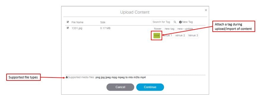
a.![]() (Optional) Add or delete available tags.
(Optional) Add or delete available tags.
b.![]() (Optional) Select available tags to be assigned to the content that you are uploading.
(Optional) Select available tags to be assigned to the content that you are uploading.
5.![]() Click Continue. The content uploads and appears in the Listview.
Click Continue. The content uploads and appears in the Listview.
Adding a URL for HTML Pass-Through Content
User Role: Administrator / Content Manager
For HTML content guidelines, see the Cisco Vision Content Planning and Specification Guide: Dynamic Signage Director, Release 6.2.
To add a URL for HTML pass-through content:
1.![]() Go to Configuration > Channel Definitions > Basic Info tab.
Go to Configuration > Channel Definitions > Basic Info tab.
Customizable Background Images for Login, DMP, or Channel Guide
Now you can upload a different login image when you login to Cisco Vision Dynamic Signage Director, upload an image to show as the background of a DMP, and upload a channel guide image. The current file types allowed are stills, no video files:.jpg,.jpeg,.png, and.gif.
For the DMP image upload, the new image will show immediately after a DMP reboot. If the DMP should lose power or connectivity for any reason, the DMP will show a black screen. Then the screen will display the Cisco logo.
To upload a different image to the DSD Login page:
1.![]() Go to More > Manage Software > Default Images.
Go to More > Manage Software > Default Images.
2.![]() Click Login Background Image (Figure 54).
Click Login Background Image (Figure 54).
3.![]() Click Upload. Choose a new image. Click OK.
Click Upload. Choose a new image. Click OK.
Note: When a DMP is configured for portrait mode, the DMP scales the image to fit (not to fill). The display may show black areas where the image does not fill.
Figure 54 Uploading a New DSD Login Image
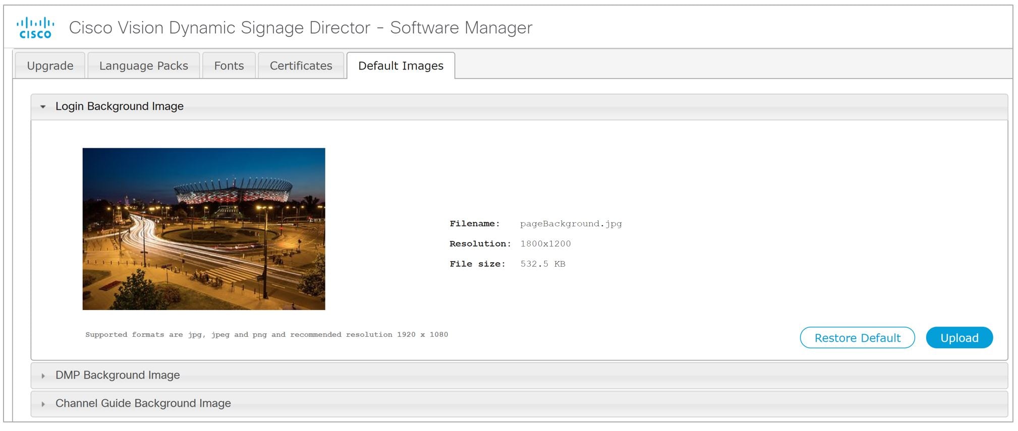
This example shows only the login image upload. Open the DMP Background Image or Channel Guide Background Image drop-downs. The file size and type of file is limited. For instance, the limitation of file sizes apply to the new image you plan to display on the DMP, too. It displays with proper aspect ratio, depending on the screen size of the device you are changing.
We recommend an image that is 1920 X 1080 resolution. Use Restore Default if you need to return to the default images.
Staging Content to the Media Player
Once you have content uploaded to Cisco Vision Director, it must be pushed to the media player before it can be run by a script. This process of pushing content to the media player is called content staging.
Content staging needs to be done when:
■![]() New custom fonts, language packs, or new login, DMP, or channel guide background default images have been installed or uploaded in the Software Manager.
New custom fonts, language packs, or new login, DMP, or channel guide background default images have been installed or uploaded in the Software Manager.
■![]() There have been changes to any content imported to the content Library (CMS). This includes local video and graphics files, and channels.
There have been changes to any content imported to the content Library (CMS). This includes local video and graphics files, and channels.
Note : Changes to widgets or data integration sources do not require content staging. But you must stage content to the DMP if you change content in a script or change content already assigned to a DMP within a particular script.
There are two ways that you can stage content from the Main Menu:
■![]() Staging content manually
Staging content manually
Manual content staging is performed outside the actual running of the script using the Staging button on the Script Management > Staging screen. With this method, you can stage content per script for all media players, or by selected media players.
Note : Only Administrator and Event Operator roles can stage content manually. Venue operator roles cannot stage content this way.
■![]() Scheduling content staging
Scheduling content staging
With this method, you can schedule content staging to occur at a specified number of minutes ahead of script start, or at a script start.
Staging Content Manually
User Role: Administrator / Event Operator
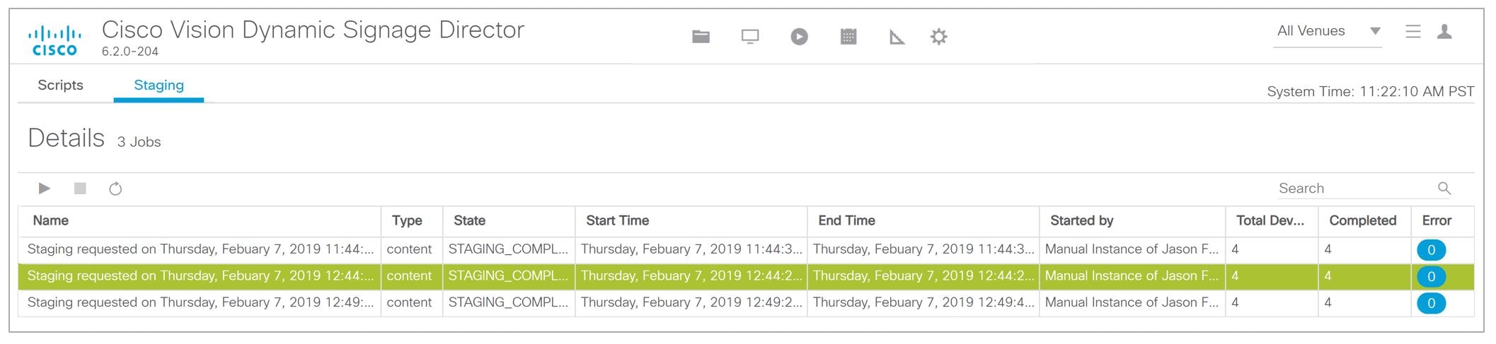
1.![]() Go to Script Management > Staging tab (Figure 55).
Go to Script Management > Staging tab (Figure 55).
2.![]() Select the script whose content you need to update on the media players.
Select the script whose content you need to update on the media players.
3.![]() Click the Play icon. The Start Manual Staging box appears (Figure 56).
Click the Play icon. The Start Manual Staging box appears (Figure 56).
4.![]() In the Staging screen, select the script you want to stage in the For Script field. Use the pull-down arrow.
In the Staging screen, select the script you want to stage in the For Script field. Use the pull-down arrow.
Figure 56 Start Manual Staging Dialog Box
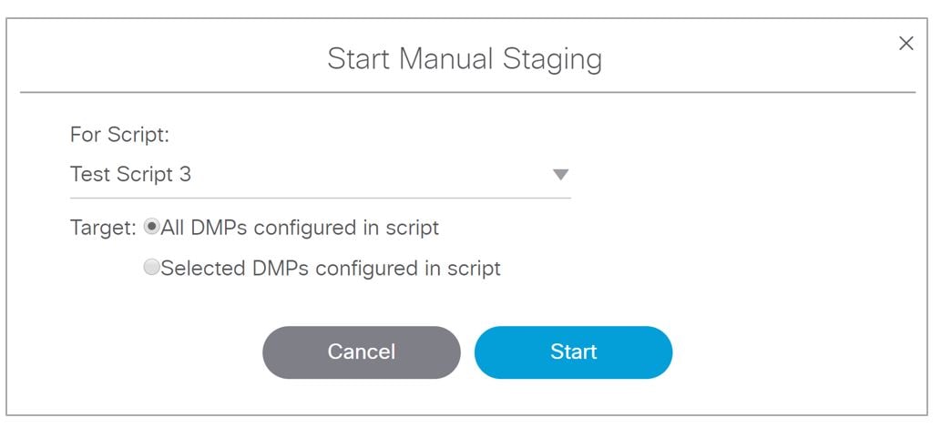
5.![]() Select the target media players to receive the content updates. If you click “Selected DMPs configured in script,” a list of available media players appears (Figure 57).
Select the target media players to receive the content updates. If you click “Selected DMPs configured in script,” a list of available media players appears (Figure 57).
Figure 57 Selected DMPs Configured in Script

6.![]() Select the available media players to receive the content updates. Use the scroll bar to find the DMP. Use the Shift and Control keys to select multiple DMPs.
Select the available media players to receive the content updates. Use the scroll bar to find the DMP. Use the Shift and Control keys to select multiple DMPs.
Scheduling Content Staging with Script Start
User Role: Administrator / Event Operator / Venue Operator
Be advised: a script will not start until staging is complete, even if 0 minutes ahead of script start is configured. Determine how long before the script start to schedule the staging.
For more information about starting event scripts, see also the Starting an Event Script.
To schedule content staging with script start:
1.![]() Go to Script Management > Script tab. The Script Details screen appears (Figure 58) with your scripts.
Go to Script Management > Script tab. The Script Details screen appears (Figure 58) with your scripts.
Figure 58 Script Details Screen
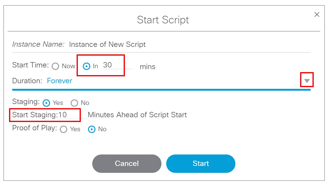
3.![]() Click Start. The Start Script dialog box appears (Figure 59).
Click Start. The Start Script dialog box appears (Figure 59).
Figure 59 Start Script Dialog Box
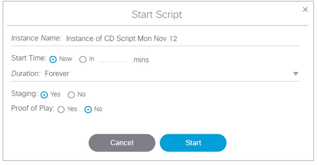
4.![]() Set the start time as Now or type in the minutes.
Set the start time as Now or type in the minutes.
5.![]() Use the drop-down arrow to choose the Duration. The duration has values listed in seconds.
Use the drop-down arrow to choose the Duration. The duration has values listed in seconds.
6.![]() Click the Staging Yes or No button.
Click the Staging Yes or No button.
a.![]() Type in the Minutes Ahead of Script Start to stage content to the media players (Script Start).
Type in the Minutes Ahead of Script Start to stage content to the media players (Script Start).
b.![]() To run staging immediately before running the script, specify a value of 0. The script will not start until staging is complete.
To run staging immediately before running the script, specify a value of 0. The script will not start until staging is complete.
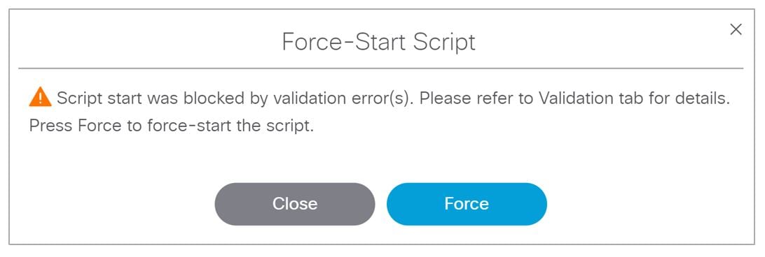
If the script start is blocked by validation error(s), Figure 60 appears.
Figure 60 Confirm Force Script Start
Use the drop-down arrow to see more information on your script. The Status column shows “ Starting.” When complete, see “Past” and icon, as well as the date and time in the Started column.
Click the Staging tab to see the details of your job. Double click the Error icon to see how to resolve the error.
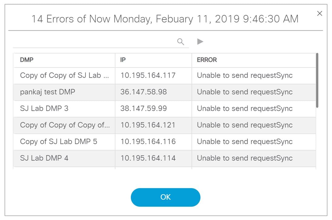
 Feedback