Cisco PWR-IE240W-AC-IEC and PWR-IE400W-AC-IEC Power Supply Units
The Cisco power supply units (PSU) are DIN rail mounted AC to DC PSUs with IEC C16 input connector, designed for use with Cisco IE series DIN rail mounted switches.
The two models are:
-
PWR-IE240W-AC-IEC
-
PWR-IE400W-AC-IEC
Compatible Products
These PSUs are designed for use with DIN rail mounted Cisco Industrial Ethernet switch families.
 Note |
Refer to individual switch documentation for specific power requirements and PoE budgets. |
Protection Features
This section describes the PSU protection features.
|
Feature |
Trigger Threshold |
Protection Type |
Recovery |
|---|---|---|---|
|
Over-Current Protection (OCP) |
Trips at >120% of rated load current |
Hiccup mode, non-latching |
Automatic when fault is cleared |
|
Over-Voltage Protection (OVP) |
Limits the DC output to <60 V |
Non-latching |
Power cycle required |
|
Thermal Protection |
Auto shutdown if internal temperature exceeds safe limits |
Non-latching |
Automatic when temperature returns to normal range |
Note |
If the PSU enters protection mode repeatedly, disconnect the load and inspect for faults before reconnecting. Check that ambient temperature is within the operating range, airflow is not obstructed, and that the load does not exceed the derated capacity at elevated temperatures. |
Front Panel
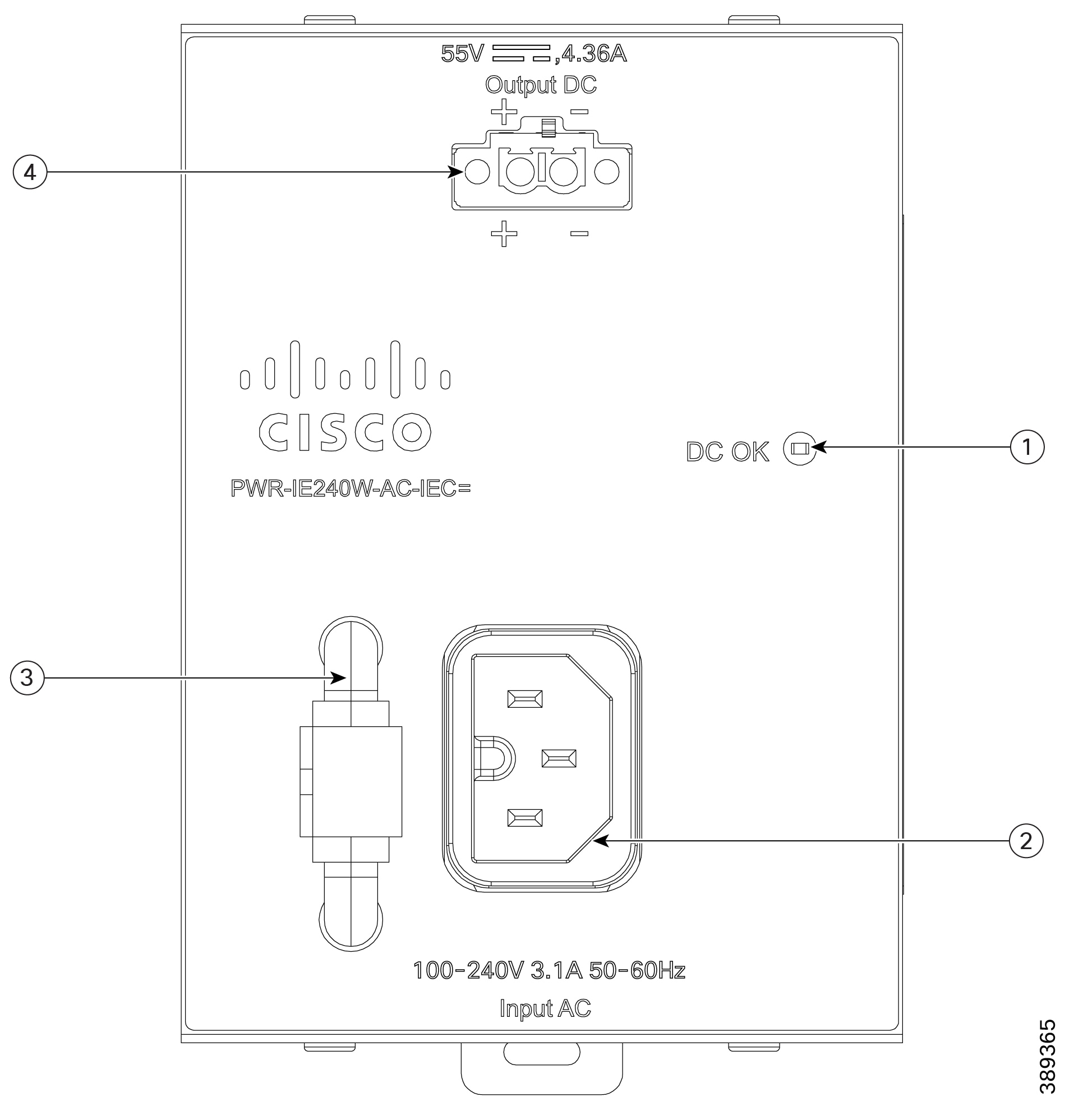
|
1 |
Status LED |
3 |
Cable Strain Relief and hook-and-loop strap |
|
2 |
AC Input Connector |
4 |
DC Output Connector |
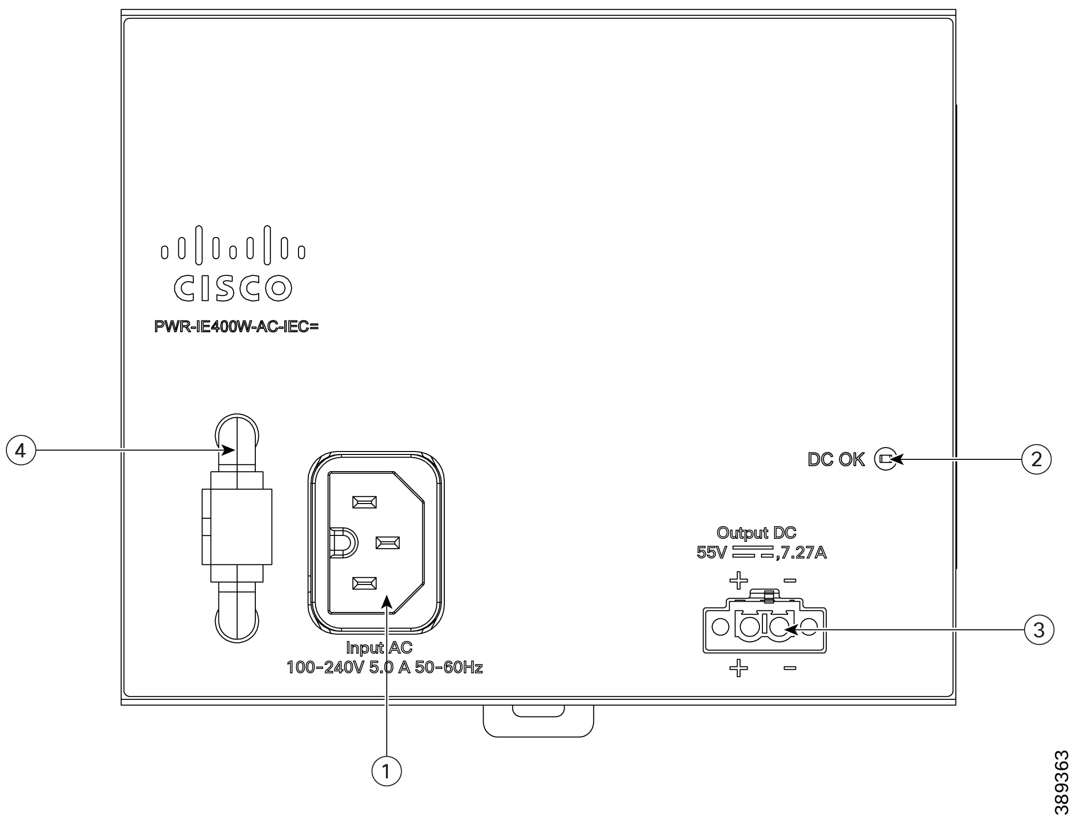
|
1 |
AC Input Connector |
3 |
DC Output Connector |
|
2 |
Status LED |
4 |
Cable Strain Relief and hook-and-loop strap |
LED status
|
LED |
Status |
Description |
|---|---|---|
|
DC OK |
Green—ON |
DC output voltage is within specifications (54-56 VDC) and operating normally |
|
OFF |
DC output is not present or out of specifications |
Package Contents
This section lists the items included in the box.
-
Cisco PWR-IExxxW-AC-IEC PSU
-
One user selected country-based AC input cable
-
One user selected DC power output cable:
-
CAB-DC-381=—DC power cable for switches with a 3.81mm power input (Such as IE3100 and IE3105), 1 meter length.
-
CAB-DC-500=—DC power cable for switches with a 5.00mm power input (Such as IE3500 and IE3505), 1 meter length.
DC Cables can also be ordered separately for replacement purposes.
-
If any item is missing or damaged, contact your Cisco representative or reseller.
Orderable Replacement Parts
Refer to the following PIDs to identify and order the correct replacement for your power supply unit or DC power cable.
|
PID |
Description |
|---|---|
|
PWR-IE240W-AC-IEC |
240W AC to DC power supply with IEC connector |
|
PWR-IE400W-AC-IEC |
400W AC to DC power supply with IEC connector |
|
PID |
Description |
Compatible Switches |
|---|---|---|
|
CAB-DC-381= |
DC Power Cable with 3.81mm connector, 1 meter length |
IE switches with 3.81mm power input connector |
|
CAB-DC-500= |
DC Power Cable with 5.00mm connector, 1 meter length |
IE switches with 5.00mm power input connector |
Note |
DC power cable is included with PSU purchase. Order separately only for replacement purposes. |
Serviceability
The PSUs are not field-serviceable. No user-serviceable parts are inside.
-
Replacement—In the event of PSU failure, replace the entire unit.
-
Return Material Authorization (RMA)—Contact Cisco Technical Assistance Center (TAC) for RMA procedures.
Mounting Instructions
This section describes the mounting procedure for the Cisco PWR-IExxxW-AC-IEC PSUs.
-
DIN rail mount
These power supplies are UL-certified for non-professional installation.
Mount the PSU on the DIN rail
This procedure guides you to mount the PSUs on standard IEC/EN 60715 top hat DIN rails 35-15 and 35-7.5.
Both PSUs are intended for individual mounting adjacent to the Cisco IE DIN rail switch. To ensure proper cooling, maintain the clearance between the switch and the power supply as specified in the IE switch documentation.
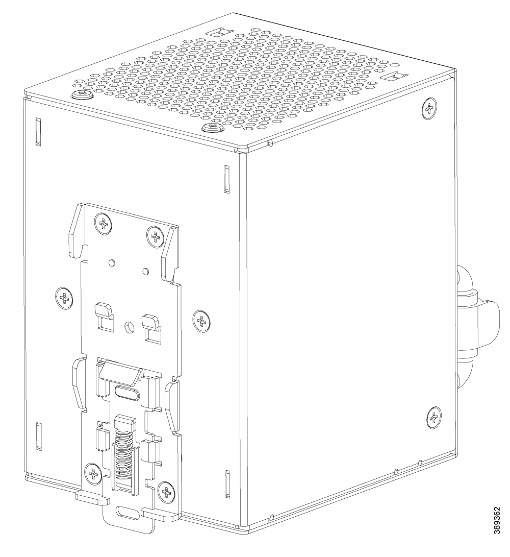
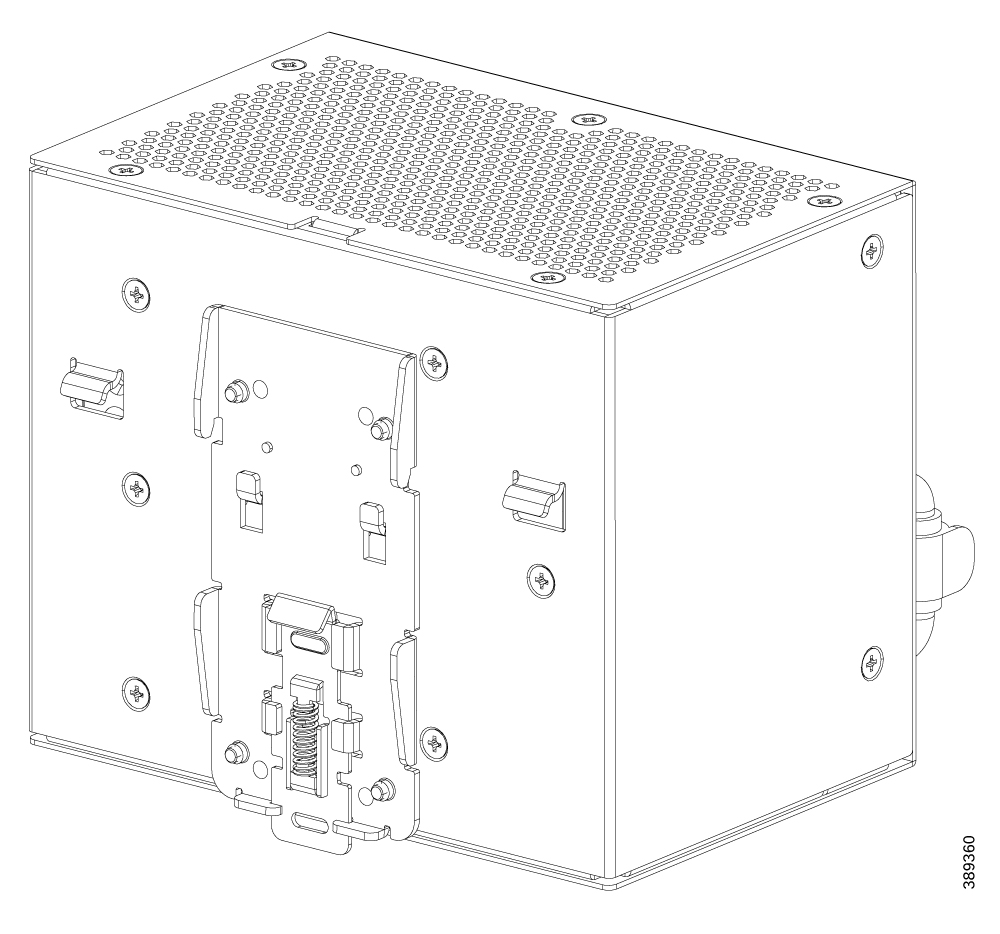
Before you begin
|
Materials Needed |
Supplied with the PSU |
|---|---|
|
Power supply unit |
Yes |
|
Standard IEC/EN 60715 top hat DIN rails 35-15 and 35-7.5 |
No |
|
Flat-head screwdriver |
No |
Procedure
|
Step 1 |
Position the DIN rail in the desired location within your enclosure. To ensure proper performance, maintain 1.0 inch (25 mm) of clearance at the top and bottom, 1.0 inch (25 mm) on the sides, and sufficient space for the PSU depth and cable bend radius, while verifying that ambient conditions meet the thermal derating profile. |
|
Step 2 |
Attach the PSU.
|
|
Step 3 |
Route the cables.
|
|
Step 4 |
Verify the PSU is firmly attached by gently pulling on it. |
Connect the DC output power cable
This procedure describes how to connect a compatible Cisco IE switch to the PSU and supply power using the DC power cable.
Before you begin
|
Materials Needed |
Supplied with the PSU |
|---|---|
|
DC power cable (CAB-DC-381= or CAB-DC-500=) |
Yes |
|
Screwdriver |
No |
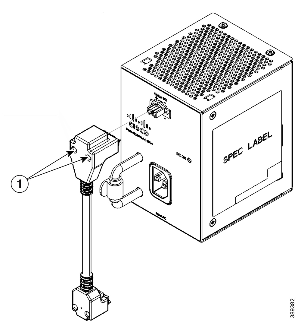
|
1 |
Retention screws |
Procedure
|
Step 1 |
Plug the DC cable's male connector into the PSU’s 2-pin DC Output Connector. The connector is keyed to prevent backwards connection. Firmly seat the connector without using excessive force, then secure it by tightening the retention screws to 3.5 in-lb (0.4 Nm) of torque. |
|
Step 2 |
Identify the mating connector on the Cisco IE switch. Ensure that you use the correct DC cable (3.81 mm or 5.00 mm) based on the DC connector on the Cisco IE switch. |
|
Step 3 |
Route the opposite end (female end) of the cable to the switch. Firmly insert the connector into the switch's DC Power Input. Tighten the retention screws. |
|
Step 4 |
Verify all connections are secure by gently pulling on each connector. |
Connect the AC input power cable
This procedure describes how to connect the input AC power cable to the PSU.
Before you begin
 Warning |
To prevent the risk of electric shock, this equipment must be properly grounded. Always connect the 3-prong AC power cord to a grounded (earthed) outlet. Do not use 3-pin to 2-pin conversion adapters or any other device that defeats the protective ground connection. Maintaining a continuous ground path is essential for the safe operation of this power supply |
Warning |
To prevent electrical arcing and damage, always connect your DC cables first before plugging in the AC power. Similarly, always unplug the AC power before disconnecting the DC cables. |
|
Materials Needed |
Supplied in the Kit |
|---|---|
|
AC power cable with IEC C15 connector |
Choose region specific power cord while ordering the PSU |
Note |
The IEC C15 power cord must comply with local electrical codes. |
Procedure
|
Step 1 |
Insert the IEC C15 plug fully into the PSU inlet.
|
||
|
Step 2 |
Connect the cord’s plug to a grounded AC outlet within the rated 90–264 VAC range. |
||
|
Step 3 |
Verify the cable is securely connected by gently pulling the connector on both ends of the cable. |
Dual Power Supply Redundancy Setup
This section desribes the procedure to set up power redundancy for the Cisco IE switch using PWR-IExxxW-AC-IEC PSUs.
Note |
In systems configured with the redundant power option, connect each of the two power supplies to separate independent power sources. Failure to isolate power feeds introduces a single point of failure, risking system shutdown due to external wiring faults or circuit breaker trips. |
Follow the installation steps for each unit, connecting them to separate power inputs on the switch.
Technical Specifications
This section provides the technical specifications for the Cisco PWR-IExxxW-AC-IEC series PSUs.
Note |
While the power supply unit is rated for operation between -40°C and +85°C, the input cable restricts the system’s effective thermal envelope to -20°C to +70°C. To maintain operational integrity and prevent insulation degradation, ensure ambient and operational temperatures remain strictly within the input cable’s specified thermal limits. |
|
Specifications |
PWR-IE240W-AC-IEC | PWR-IE400W-AC-IEC |
|---|---|---|
|
Input voltage range and frequency |
Nominal AC input: 100-240 VAC, 50-60 Hz Supported AC input: 90-264 VAC, 47-63 Hz |
|
|
Output voltage and current |
54-56 VDC (nominal 55 V), 4.36 A, 240 W Max |
54-56 VDC (nominal 55 V), 7.27 A, 400 W Max |
|
Operating temperature |
–40 °C to +50 °C at full power |
|
|
Power derating |
>50 °C to 85 °C at 2.5%/°C |
|
|
Physical specifications (W x H x D) |
85 x 120 x 127 mm 3.34 x 4.72 x 5.0 in |
144 x 120 x 126 mm 5.66 x 4.72 x 5.0 in |
|
Weight |
2.25 lbs (1.02 kg) |
3.10lbs (1.41 kg) |
|
Non-operating temperature |
–40 °C to +85 °C |
|
|
Humidity |
Operating: 5% to 95%, non-condensing Non-operating: 5% to 95%, non-condensing |
|
|
Thermal shock |
Operating: –40 °C to +70 °C at 0.5°C/min Non-operating: –40 °C to +85 °C, 2-3 min change |
|
|
Altitude |
Operating: 5000 meters |
|
|
Reliability |
MTBF: 300,000 hrs @ 40 °C |
|
|
IP Rating |
IP 20 |
|
Mechanical Specifications
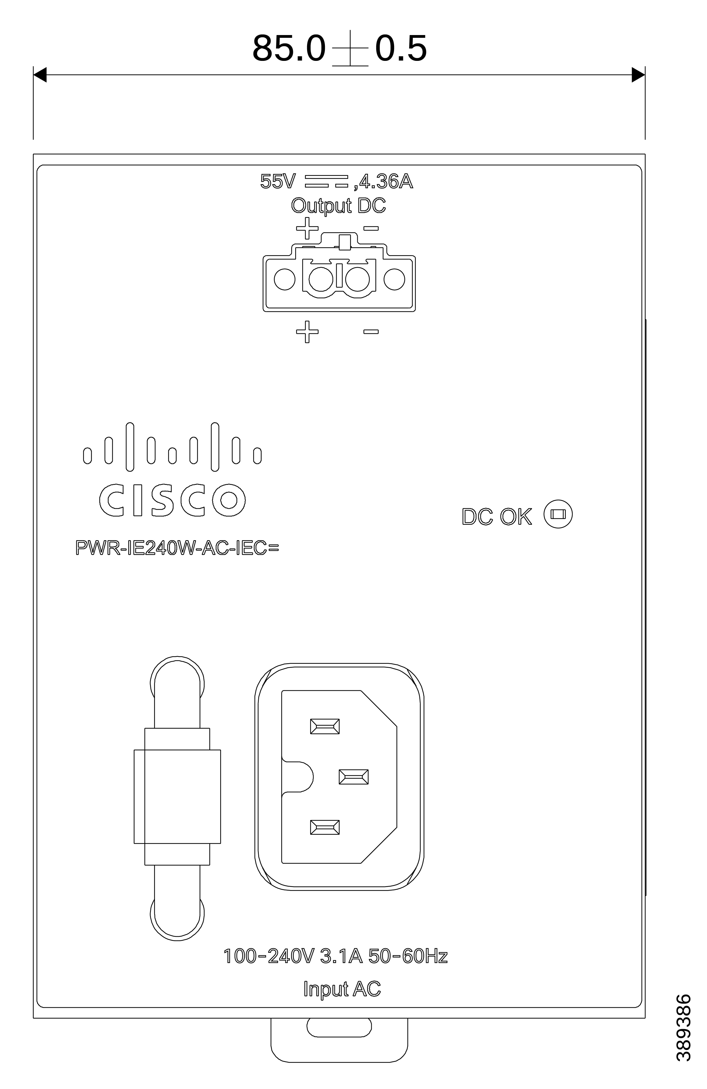
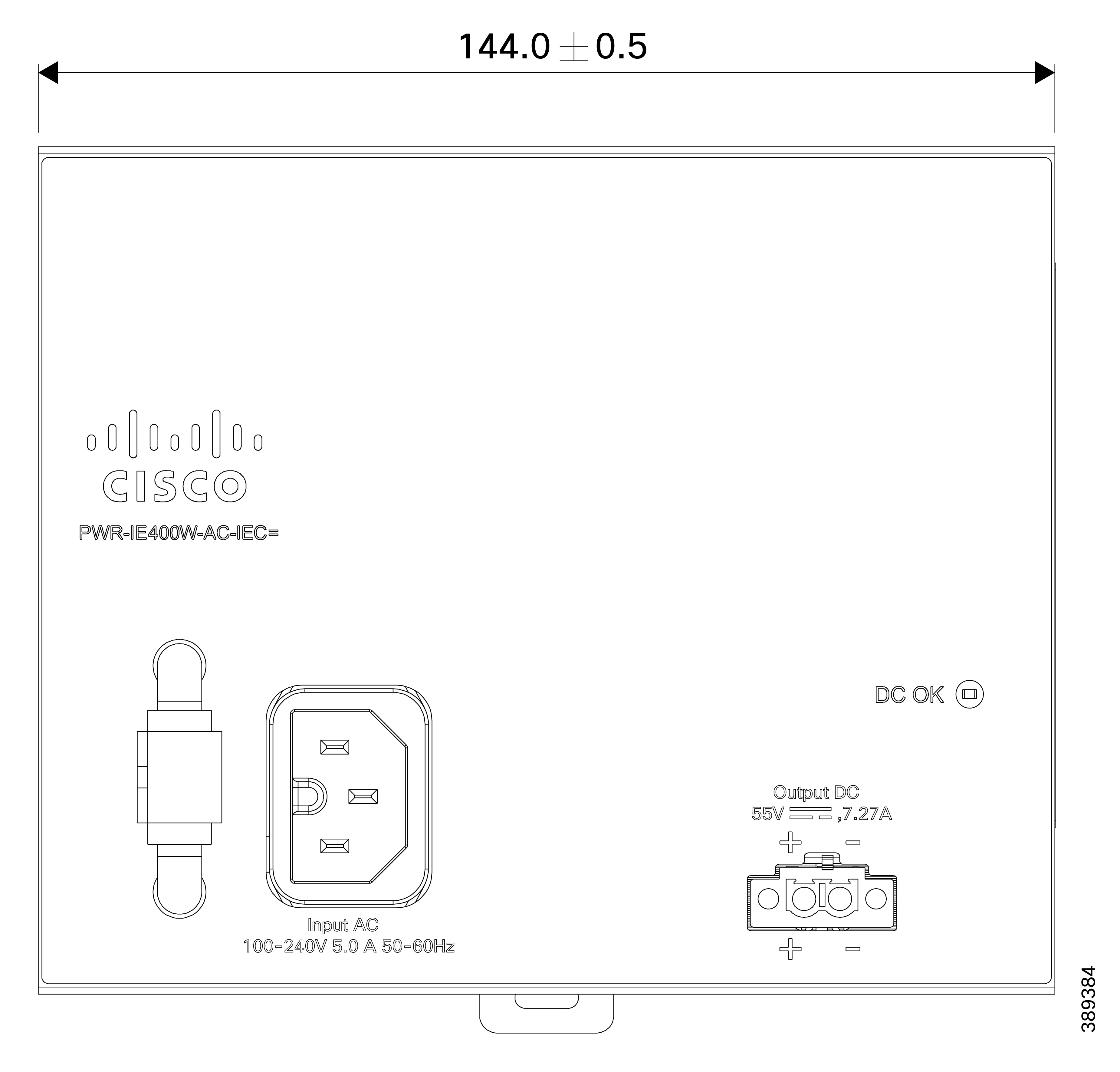
This section provides the PSU's physical dimensions.
PWR-IE240W-AC-IEC= Dimensions

PWR-IE400W-AC-IEC= Dimensions

Troubleshooting
This section lists the common issues and their solutions.
|
Symptom |
Possible Cause |
Solution |
|---|---|---|
|
DC OK LED off |
No AC input power |
Check AC power source and verify outlet has power |
|
Faulty AC power cord |
Test with known good IEC C15 power cord |
|
|
Load exceeds PSU capacity |
Reduce load or use higher capacity PSU. Check ambient temperature and derating requirements. |
|
|
Short circuit |
Disconnect input power. Inspect cables for damage |
|
|
PSU in protection mode |
Disconnect AC power, wait 30 seconds to allow the latching protection to reset. Reconnect and retry |
|
|
Internal PSU failure |
Replace PSU |
|
|
PSU operates intermittently |
Loose connections |
Verify and tighten all cable connections |
|
Over-temperature condition |
Verify adequate ventilation, check ambient temperature. Ensure ambient temperature is at or below 122°F (50°C) for full power operation. |
|
|
Overload condition |
Verify load does not exceed PSU capacity, accounting for temperature derating |
|
|
Switch does not power on |
Incorrect DC cable |
Verify correct cable type for switch model (3.81mm or 5.00mm) |
|
DC output voltage out of spec |
Check DC OK LED; if off, see above troubleshooting steps |
|
|
Faulty switch |
Test PSU with known good switch |
Safety Guidelines
Regulatory Information
Note |
Statement 2017—Class A Notice for FCC Modifying the equipment without Cisco's authorization may result in the equipment no longer complying with FCC requirements for Class A digital devices. In that event, your right to use the equipment may be limited by FCC regulations, and you may be required to correct any interference to radio or television communications at your own expense. This equipment has been tested and found to comply with the limits for a Class A digital device, pursuant to Part 15 of the FCC Rules. These limits are designed to provide reasonable protection against harmful interference when the equipment is operated in a commercial environment. This equipment generates, uses, and can radiate radio frequency energy and, if not installed and used in accordance with the instruction manual, may cause harmful interference to radio communications. Operation of this equipment in a residential area is likely to cause harmful interference in which case users are required to correct the interference at their own expense. |
Safety Warnings
Warning |
Statement 1071—Warning Definition IMPORTANT SAFETY INSTRUCTIONS Before you work on any equipment, be aware of the hazards involved with electrical circuitry and be familiar with standard practices for preventing accidents. Read the installation instructions before using, installing, or connecting the system to the power source. Use the statement number at the beginning of each warning statement to locate its translation in the translated safety warnings for this device. SAVE THESE INSTRUCTIONS  |
warning_nonsafety |
Statement 2009—Class A Warning To avoid electromagnetic interference, do not install or use this product in a residential environment. |
Safety Warnings
Do not install this device until you have read and understood the safety information in this section.
Warning |
This power supply has not been evaluated to IEC 60079-0/15, UL121201 or CSA213 standards and is not approved for hazardous location installations. The power supply can be used with a switch that is approved for Hazardous Locations (HazLoc). However, it must not be used in a HazLoc environment. |
-
To guarantee sufficient convection cooling, keep a distance of 1.0 in. (25 mm) above and below the device as well as a lateral distance of 1.0 in. (25 mm) to other units.
-
Install the unit with a branch circuit protective device 20A (UL489 Listed)
-
Use this equipment in a Pollution Degree 2 and at altitude up to 5000 meters.
-
Do not dispose of electrical appliances as unsorted municipal waste. Use separate collection facilities. Contact your local government for information regarding the collection systems available. If electrical appliances are disposed of in landfills or dumps, hazardous substances can leak into the groundwater and get into the food chain, damaging your health and well-being.
In countries applicable, when replacing old appliances with new ones, the retailer is legally obligated to take back your old appliance for disposal for free of charge.
Product Compliance
The power supply meets the following:
|
Safety |
UL 62368-1, CSA C22.2 No. 62368-1, CB to IEC 62368-1 and EN 62368-1 |
|
Emissions |
EN 55011, EN 55032, EN 55035, CFR 47 Part 15B: Class A, ICES-003: Class A, EN 61000-6-1, EN 61000-6-2, EN 61000-6-4, VCCI |
|
Immunity |
EN 55035, EN 61000-6-1, EN 61000-6-2, IEC 61000-4-2, IEC 61000-4-3, IEC 61000-4-4, IEC 61000-4-5, IEC 61000-4-6, IEC 61000-4-8, IEC 61000-4-11, IEC 61000-4-18 |
Note |
Statement 438—Taiwan RoHS Restricted Substances Content Disclosure Table web address: http://www.cisco.com/go/taiwanrohs |
Warning |
Statement 2012—Voluntary Control Council for Interference (VCCI) Class A Warning for Japan This is a Class A product based on the standard of the VCCI Council. If this equipment is used in a domestic environment, radio interference may occur, in which case, you may be required to take corrective actions. |
 Feedback