Introduction
This document describes configuration for a mobility deployment using an AP that supports URWB and is associated with a Catalyst 9800 Series WLC.
Background Information
This topology supports connectivity for moving assets such as vehicles or robots. It is essential for use cases that require continuous, low-latency communication while in motion.
Acronyms
- Mobility Base (MB)
- Mobility Client (MC)
- Access Point (AP)
- Ultra-Reliable Wireless Backhaul (URWB)
- Wireless LAN Controller (WLC)
Components Used
The configuration involves two different types of hardware components:
- 3x Cisco Catalyst IW9167
- C9800-40
The information in this document was created from the devices in a specific lab environment. All devices used in this document started with a cleared (default) configuration. If your network is live, ensure that you understand the potential impact of any command.
Refer to Old & New terminologies from here
URWB Mobility Network Topology Using Catalyst 9800 Controller CLI
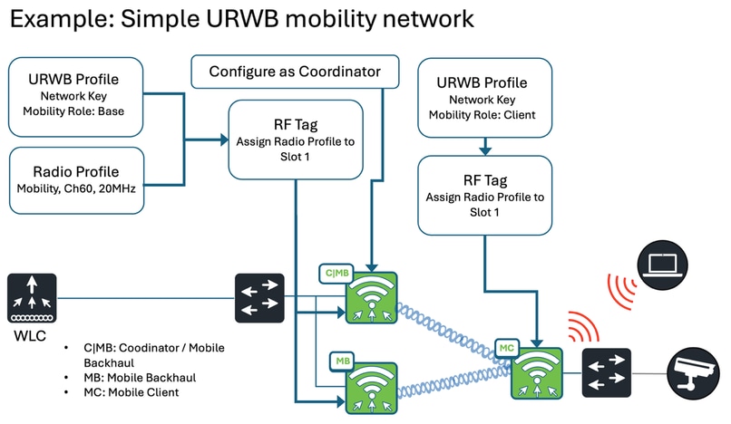
URWB Mobility Configuration from the Catalyst 9800 Controller
At a high level, three steps are required for deployment:
1. Access Points (APs) that support URWB must be associated with the Catalyst 9800 WLC.
2. Apply the necessary configuration to the Access Points.
3. Deploy the Access Points in the network.
Configuring URWB Network Profile
(Configure -> URWB Network Profile)
Network Profile for Mobility Base
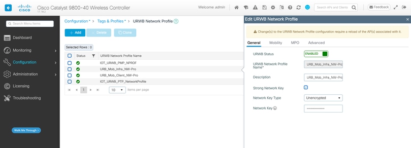
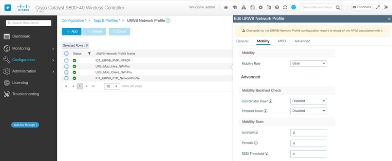
wireless profile urwb URB_Mob_Infra_NW-Pro
 description URB_Mob_Infra_NW-Pro
 strong-network-key
 network-key key 0 S3cretK3y8675309!!!
 no shutdown
Network Profile for Mobility Client
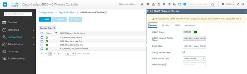
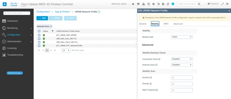
wireless profile urwb URB_Mob_Client_NW-Pro
 description URB_Mob_Client_NW-Pro
 strong-network-key
 network-key key 0 S3cretK3y8675309!!!
 mobility role client
 no shutdown
Note: In a mobility cluster, the network key for all Base and Client devices must be the same in order to establish the MPLS tunnel and communicate with each other.
Configuring Radio Profile
(Configuration -> Tags and Profiles -> Radio -> Radio Tab)
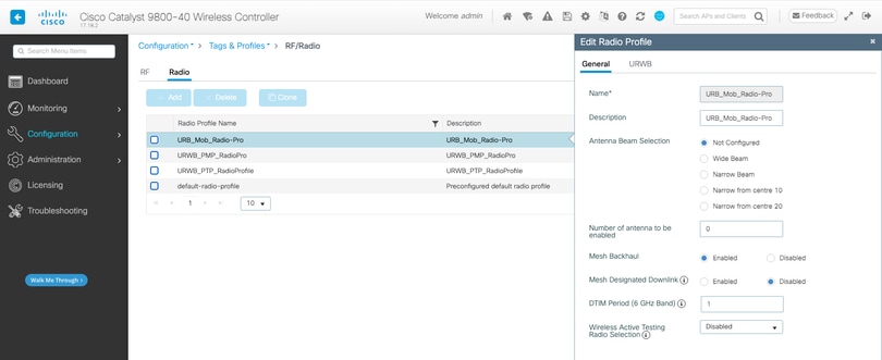
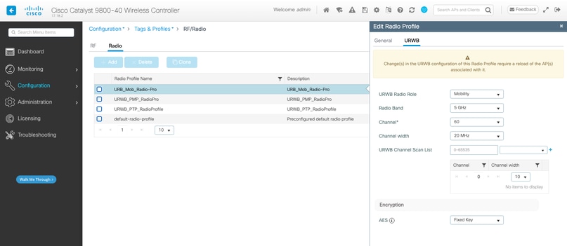
wireless profile radio URB_Mob_Radio-Pro
 description URB_Mob_Radio-Pro
 urwb channel 5Ghz 60
 urwb role mobility
Configuring RF Tags
(Configuration -> Tags and Profiles -> Tags -> RF Tab)
RF Tag for Mobile Base
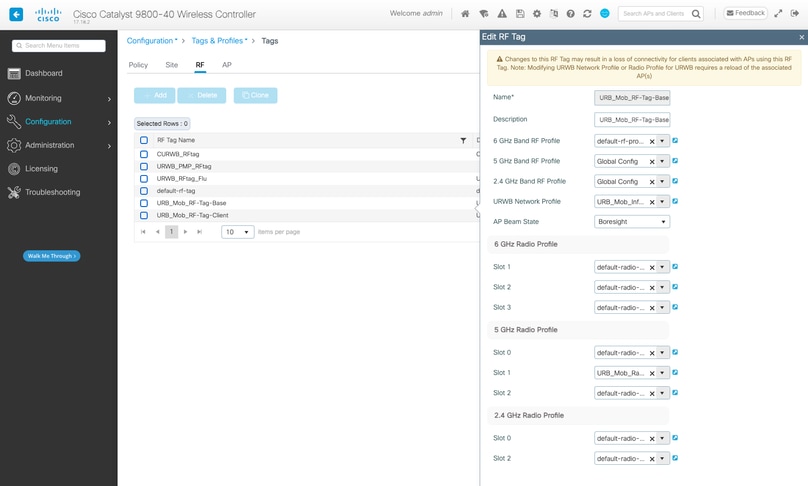
wireless tag rf URB_Mob_RF-Tag-Base
 description URB_Mob_RF-Tag-Base
 dot11 5ghz slot1 radio-profile URB_Mob_Radio-Pro
 urwb-profile URB_Mob_Infra_NW-Pro
RF Tag for Mobile Client
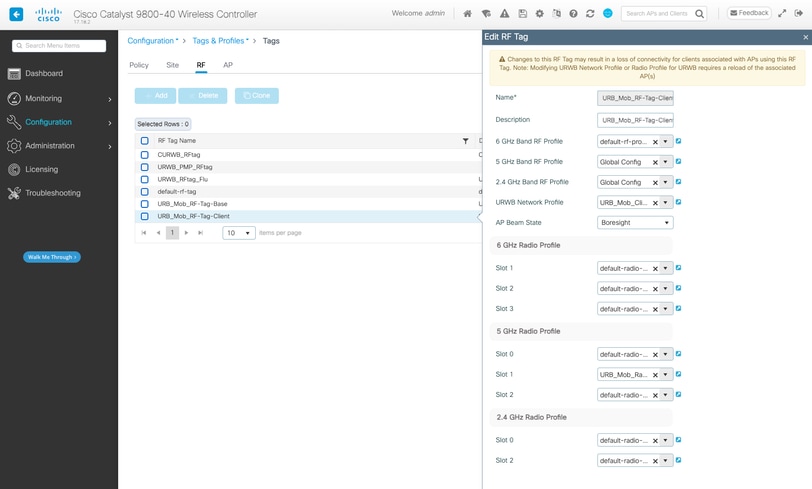
wireless tag rf URB_Mob_RF-Tag-Client
 description URB_Mob_RF-Tag-Client
 dot11 5ghz slot1 radio-profile URB_Mob_Radio-Pro
 urwb-profile URB_Mob_Client_NW-Pro
Configuring Access Points
(Configuration -> Wireless -> Access Point)
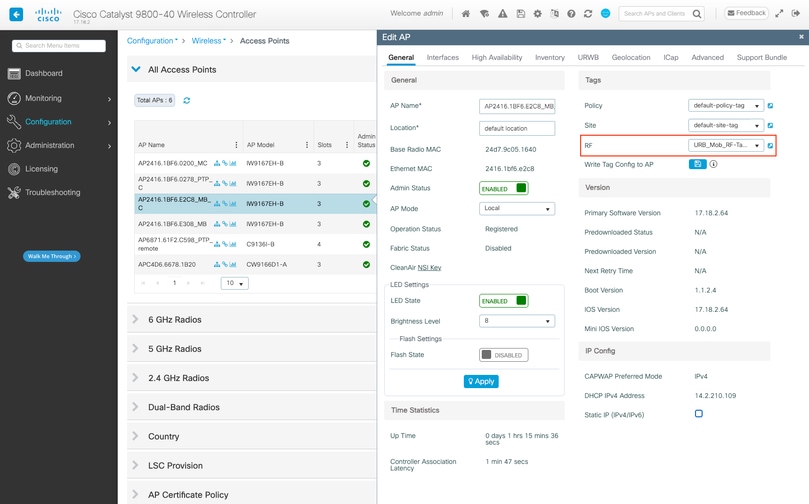
ap 2416.1bf6.0200
 rf-tag URB_Mob_RF-Tag-Client
ap 2416.1bf6.e2c8
 rf-tag URB_Mob_RF-Tag-Base
ap 2416.1bf6.e308
 rf-tag URB_Mob_RF-Tag-Base
Configuring the coordinator
(Configuration -> Wireless -> Access Point. -> URWB)
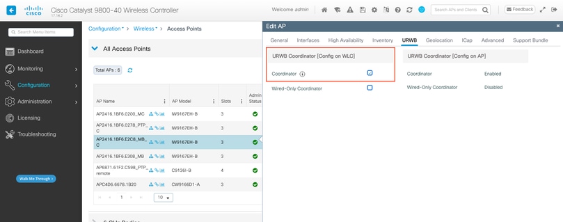
ap name <ap-name> urwb mode coordinator
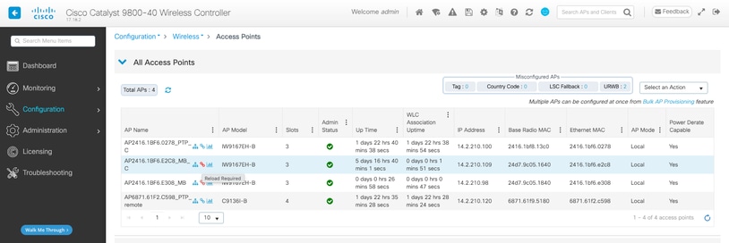
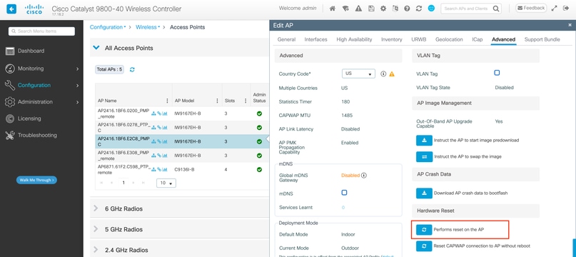
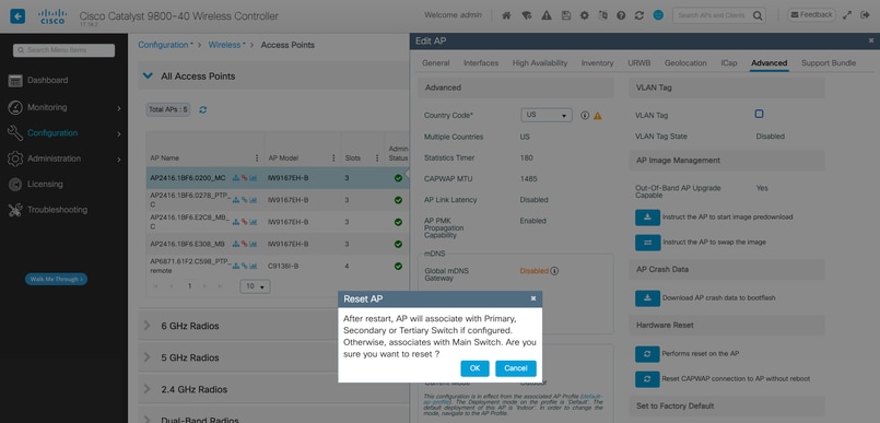
Final Steps
After configuring all settings, save the configuration and apply the changes. If the AP does not reset automatically, it can still require a reset for the changes to take effect. The AP table indicates if the AP requires a reload. If needed, it can be reloaded from the C9800. Once the Access Points (APs) reboot and the radios are back online, you can check the RSSI from the Antenna Alignment page and monitor live connectivity from the URWB Network Topology page.
Troubleshoot & Monitor the CURWB Network
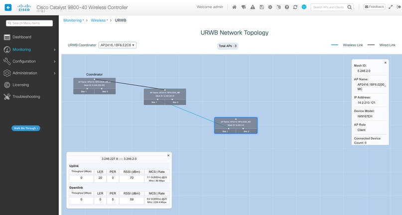
Monitoring the URWB network
(Monitoring -> Wireless -> URWB)
URWB Network Topology allows you to check different network key parameter index values for UPLINK and DOWNLINK, such as LER (Link Error Rate), PER (Packet Error Rate), RSSI (Signal Strength), throughput, and so on.
Physical Issues
- Ensure the use of CURWB-supported antennas, correctly connected to radios within recommended guidelines, and oriented in the proper direction.
- Confirm that overlapping coverage is adequate throughout the track.
- Maintain a direct line of sight for radios.
High Channel Utilization
- Mitigate interference through strategic RF planning.
- Utilize multiple frequency deployments with frequency scanning for seamless handover, requiring two radios per vehicle.
- Ensure radios are positioned at least 10 feet apart at the same height, and maintain a minimum of 3 feet between radios on the same pole to prevent interference from nearby devices.
Throughput Issues
Throughput problems can result from several factors:
- Strong signal strength is vital for optimal throughput; weaker signals reduce modulation rates and throughput. Aim for a signal strength between -45 dBm and -70 dBm.
- High channel utilization can also lead to throughput degradation.
Latency Issues
Latency issues, particularly in sensitive applications, can stem from:
- Inadequate signal strength along the track.
- Interference affecting frequency performance.
- The need for Quality of Service (QoS) configurations on radios and switches.
- Fluidity settings requiring verification and fine-tuning according to PLC configurations.
Debugs on the WLC
URWB exec debug:
set platform software trace wncd chassis active R0 urwb-exec debug
URWB config debug:
Set platform software trace wncd chassis active R0 urwb-config debug
URWB database debug:
Set platform software trace wncd chassis active R0 urwb-db debug
CLI commands on the AP
Show urwb modeconfig
Show urwb mpls config
Show urwb dot11Radio <> config
Show urwb mesh route status
Show urwb eng-stats
 Feedback