Introduction
This document describes the process to replace a 9800 Wireless Controller that operates in HA-SSO without breaking HA synchronization.
Prerequisites
Requirements
Cisco recommends that you have knowledge of these topics:
Components Used
The information in this document is based on these software and hardware versions:
-
Cisco Catalyst 9800 WLC running Cisco IOS® XE 17.9.4a
-
Cisco Catalyst Center formerly called Cisco DNA Center, Release 2.3.5.5
The information in this document was created from the devices in a specific lab environment. All of the devices used in this document started with a cleared (default) configuration. If your network is live, ensure that you understand the potential impact of any command.
Background Information
High Availability Statefull Switchover (HA-SSO) Deployment Monitored by Cisco DNA Center
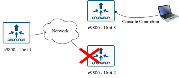
If one of the WLCs fails and must be replaced through RMA, certain procedures need to take place to ensure the replacement is smooth and causes no errors or configurations to be wiped. This process does not cause any downtime on the active WLC. This document is based on the RMA unit using the same configuration of the old unit that is to be replaced; same WMI, RMI IP address, and so on. If you want to use an RMI IP address other than the one that was configured, the procedure needs downtime as this RMI address needs to be updated on the Active unit too that requires a reboot to take effect.
In this example:
The standby unit is replaced in this scenario.
Network Diagram
Configure
Before You Start
-
Back up the configuration from the active controller.
-
Remove the faulty WLC from the rack and disconnect it from the network.
-
Connect to the console of the new (RMA) WLC, referred to as Unit3, but do not connect it to the network yet.
Wireless LAN Controller Configurations
1. Version and Install Mode
The software version and install mode must match between the two controllers; otherwise, HA SSO is not going to form.
If versions or modes differ:
- Upgrade or downgrade the RMA WLC to match the active WLC. Here is the upgrade process
- Ensure both are in INSTALL mode (not BUNDLE mode).
Here are the commands to verify:
Unit3# show version | i Version
Cisco IOS XE software, Version 17.09.04a

Unit3# show version | i Installation mode
Router operating mode: Autonomous
Installation mode is INSTALL
2. VLAN, SVI, and WMI
Create the same VLAN and SVI on Unit3, and configure the Wireless Management Interface (WMI) with a primary IP and a secondary IP (the RMI address). The RMI IP must match the RMI IP of the failed standby WLC. You can verify this on the active WLC using "show chassis" and noting the old standby IP.
Here is an example from the lab:
Unit3(config)#Vlan1122
Unit3(config-vlan)#exit
Unit3(config)#interface Vlan1122
Unit3(config-if)#ip address 10.201.166.180 255.255.255.0
Unit3(config-if)#ip address 10.201.166.163 255.255.255.0 secondary
Unit3(config-if)#exit
Unit3(config)#wireless management interface vlan 1122

Note: The RMI and WMI IP addresses must be in the same subnet as the active WLC’s WMI.
3. Network Connectivity / Physical Interface
Configure the uplink interface and allow the required VLANs.
You can either shut down the interface or leave the cable disconnected until the final step.
Unit3(config)# interface twoGigabitEthernet 0/0/0
Unit3(config-if)#switchport mode trunk
Unit3(config-if)#switchport trunk native vlan 1122
Unit3(config-if)#switchport trunk allowed vlan 1104-1126,3000
4. Chassis Number
By default, the chassis number is set to 1.
Ensure that both WLCs do not share the same chassis number to avoid conflicts. Each controller must have a unique identity for a properly functioning HA-SSO Deployment.
As changing the chassis number requires a reboot, it is best to modify the standby (Unit3) as needed before connecting it to the network.
In our scenario, we have the active Unit1 chassis number set to 2, so there is no need to make a change to the chassis for the RMA-ed WLC as it is set to 1 by default.
Here is how to check the chassis number on the active unit:
Unit1#show chassis
Chassis/Stack Mac Address : 00a3.8e23.a0e0 - Local Mac Address
Mac persistency wait time: Indefinite
Local Redundancy Port Type: Twisted Pair
H/W Current

Chassis# Role Mac Address Priority Version State IP
------------------------------------------------------------------------------------
1 Member 0000.0000.0000 0 V02 Removed 169.254.166.163
*2 Active 00a3.8e23.a0e0 2 V02 Ready 169.254.166.164
If renumbering is needed on the RMA "Unit3" unit:
Unit3#show chassis
Chassis/Stack Mac Address : yyyy.yyyy.yyyy  - Local Mac Address
Mac persistency wait time: Indefinite
H/W Current
Chassis# Role Mac Address Priority Version State IP
-------------------------------------------------------------------------------------
*1 Active yyyy.yyyy.yyyy 1 V02 Ready 0.0.0.0

Unit3#chassis 1 renumber x
WARNING: Changing the switch number may result in a configuration change for that switch. The interface configuration associated with the old switch number remain as a provisioned configuration. The new switch number be effective after the next reboot. Do you want to continue?[y/n]? [yes]: yes
This reload is not required at this point. We require it in the last step when we are reconnecting this unit to the network to let the rest of the configuration take effect.
Note: Chassis renumbering require a reboot to take effect.
5. Chassis Priority
Chassis priority determines which WLC becomes the active unit and whose configuration be inherited; Priority 2 is the highest. If both WLCs have equal priority, the election process use the chassis serial number as a tiebreaker.
In our scenario, both controllers have a priority of 1 as you can see below, so we need to change the priority on the active Unit1 to make it higher, hence priority 2.
Unit3#show chassis
Chassis/Stack Mac Address : yyyy.yyyy.yyyy
Mac persistency wait time: Indefinite
H/W Current
Chassis# Role Mac Address Priority Version State IP
-------------------------------------------------------------------------------------
*1 Active yyyy.yyyy.yyyy 1 V02 Ready 0.0.0.0
On the Active Unit1:
Unit1#show chassis
Chassis/Stack Mac Address : xxxx.xxxx.xxxx - Local Mac Address
Mac persistency wait time: Indefinite
Local Redundancy Port Type: Twisted Pair
H/W Current
Chassis# Role Mac Address Priority Version State IP
-------------------------------------------------------------------------------------
1 Member 0000.0000.0000 0 V02 Removed 169.254.166.163
*2 Active 00a3.8e23.a0e0 1 V02 Ready 169.254.166.164

Unit1#chassis 2 priority 2

Unit1#show chassis
Chassis/Stack Mac Address : 00a3.8e23.a0e0 - Local Mac Address
Mac persistency wait time: Indefinite
Local Redundancy Port Type: Twisted Pair
H/W Current
Chassis# Role Mac Address Priority Version State IP
-------------------------------------------------------------------------------------
1 Member 0000.0000.0000 0 V02 Removed 169.254.166.163
*2 Active 00a3.8e23.a0e0 2 V02 Ready 169.254.166.164
Note: Changing the priority on the WLC does not require a reboot.
6. Redundancy Config
Your active chassis number and its RMI IP determines these redundancy configurations. Match the redundancy configuration from the active WLC.
Unit3(config)#redundancy-management interface Vlan1122 chassis 1 address 169.254.166.163 chassis 2 address 169.254.166.164
Unit3(config)#exit
Unit3#wr
7. Reload and Connect the Uplink + RP Port
This last step is important to do in the right order to ensure that the active WLC does not reboot. After ensuring that you have saved the configuration and verified all the changes made on the RMA-ed Unit3, it is ready to be placed in the rack where the faulty controller was and connected to the network. Then, we need to reboot for the previous configuration to take effect. While this reboot is happening, connect the RP port back-to-back with the active Unit1. It is very critical to connect the RP before the device comes up to prevent the active from reloading.
This step must be performed in the correct order to prevent an unplanned reboot of the active WLC.
- Save the configuration and verify all settings on Unit3.
- Mount Unit3 in the rack where the faulty controller was located.
- Connect it to the network.
- Reboot Unit3 for all configuration changes to take effect.
- While Unit3 is rebooting, connect the Redundancy Port (RP) directly to the active WLC (Unit1).

Caution: Connect the RP port before Unit3 finishes booting. If the RP is connected after the controller has fully booted, both WLCs reload, which we aim to avoid.
Cisco Catalyst Center Integration
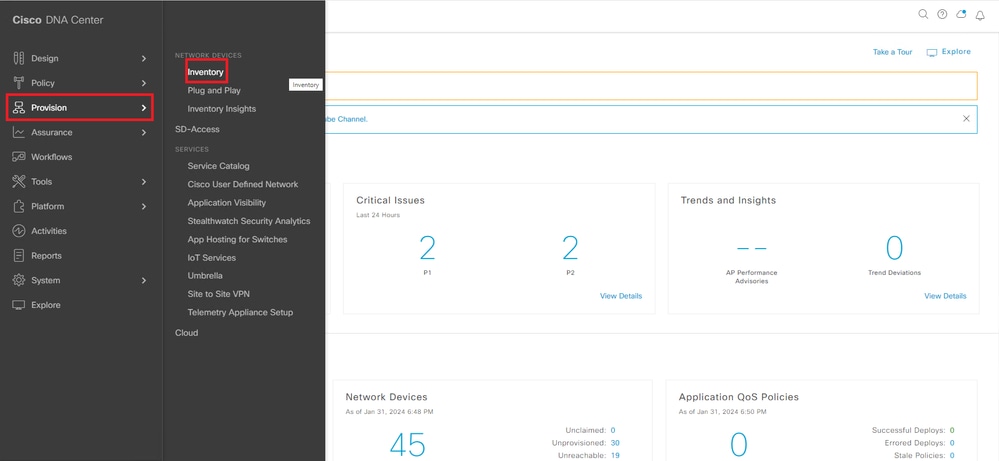
Before re-establishing HA-SSO, Cisco Catalyst Center displays the controller as a single, standalone device, as showen in the screenshot here:

After rebuilding HA-SSO from the 9800 Console connection, perform a resync in Cisco Catalyst Center to register the RMA unit’s new serial number.
Note: You DO NOT need to add Unite 3 to Catalyst Center.
1. In Cisco Catalyst Center, navigate to Provision > Inventory.
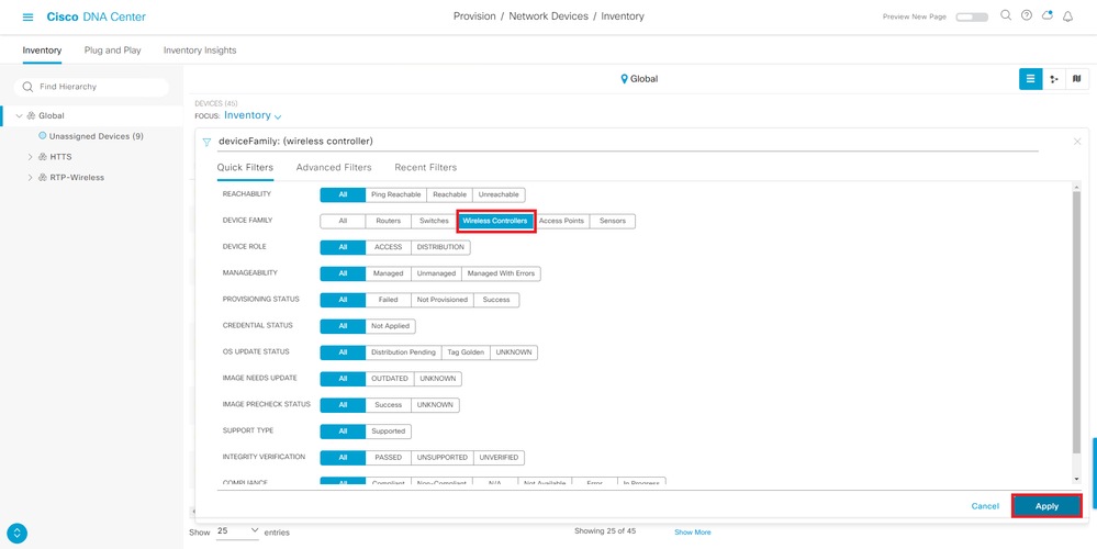
2. Select Filter → Wireless Controller.
3. Locate the active WLC, which currently shows no peer.

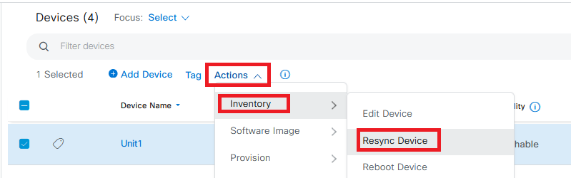
4. Select Actions > Inventory > Resync Device.
5. Wait some time for the resync to complete. Both serial numbers appears and be updated in the Catalyst Center database.
Verify and Troubleshoot
On Cisco Catalyst Center, verify that the WLC entry shows both serial numbers and the HA icon next to the WLC name.

On the Wireless LAN Controller CLI, confirm the correct priority levels and RMI IP addresses:
Unit1#show chassis
Chassis/Stack Mac Address : xxxx.xxxx.xxxx - Local Mac Address
Mac persistency wait time: Indefinite
Local Redundancy Port Type: Twisted Pair
H/W Current
Chassis# Role Mac Address Priority Version State IP
-------------------------------------------------------------------------------------
*1 Active f87a.411b.cfa0 2 V02 Ready 169.254.166.163
2 Standby 706d.1535.8300 1 V02 Ready 169.254.166.16
Related Links
Replace-c9800-Unit-in-an-Online-HA-SSO-with-no-Downtime
Cisco Catalyst 9800 Series Wireless Controller Software Configuration Guide, Cisco IOS XE Cupertino 17.9.x
 Feedback