Introduction
This document describes guidance for the understanding and resolution of doubts related to Vocera broadcast in the 9800 Wireless LAN Controller (WLC).
Prerequisites
Requirements
Cisco recommends to have knowledge of these topics:
- Basic knowledge of the WLC and Lightweight Access Points (LAPs)
- Basic knowledge of multicast modes cconfiguration on the WLC 9800
- Basic knowledge of wired multicast routing
Components Used
The information in this document is based on these software and hardware versions:
The information in this document was created from the devices in a specific lab environment. All of the devices used in this document started with a cleared (default) configuration. If your network is live, ensure that you understand the potential impact of any command.
Background Information
This article focuses on networks that operate in multicast-to-multicast mode on the WLC. A Vocera badge user can call and communicate to a group of Vocera badge wearers at the same time by using the Broadcast command. When a user broadcasts to a group, the user badge sends the command to the Vocera server, which then looks up the members of a group, determines which members of the group are active, assigns a multicast address to use for this broadcast session, and sends a message to each active user badge instructing it to join the multicast group with the assigned multicast address.
Packet Flow
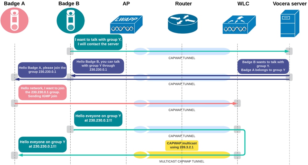
The Vocera broadcast communication follows a specific set of steps when triggered:
- The Vocera Badge user presses the button and says: Broadcast (groupname).
- The badge sends a unicast frame to the Vocera Server requesting a multicast group.
- The AP receives the packet from the badge and encapsulates the packet in CAPWAP and forwards it to the WLC as a CAPWAP unicast packet.
- The WLC decapsulates the packet and forwards the original packet to the Vocera Server.
- The Vocera Server receives the broadcast request and checks the group membership and determines which badges are currently active.
- The Vocera server assigns a multicast group address (from the range 230.230.0.1 – 230.230.15.254) and sends instructions to each active badge to join the multicast group.
- These packets travel over the LAN back to the WLC, which encapsulates them in CAPWAP unicast and forwards them to each AP with active badges.
- The AP decapsulates and transmits them over the air to the corresponding badges.
- Each badge that receives the instruction sends a IGMP Join request, which is received by the AP and then forwarded to the WLC in CAPWAP unicast packet.
- The badge that initiated the broadcast sends its voice stream using the assigned multicast address, which is received by the AP and then forwarded to the WLC in CAPWAP unicast packet.
- The WLC converts this into a CAPWAP multicast stream, forwarding it to all APs.
- If IGMP snooping is enabled on the WLC:
- The controller forwards it to all the APs. However, only the APs that have active clients subscribed to the multicast group forward the multicast traffic on that particular WLAN.
- If IGMP snooping is disabled on the WLC:
- Access points that receive the packet, forwards it to all the BSSIDs mapped to the VLAN on which clients receive multicast traffic.
- Each AP decapsulates and sends the original Vocera multicast packets over-the-air to the badges.
Configure
Enable Global Multicast
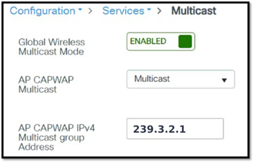
You need to ensure the uniqueness of the CAPWAP multicast address, it must not be shared anywhere in the network. there can be situations where the CAPWAP multicast address overlaps with the Vocera broadcast multicast range, so you need to confirm it does not overlap. In the provided example, the WLC uses the address 239.3.2.1 to tunnel the Vocera broadcast. Therefore, if multicast routing is required on the network, it is important to focus on this address and not the Vocera broadcast, as it is being tunneled through the CAPWAP multicast.
In the GUI:
- To configure the capwap multicast, navigate to Configuration > Services > Multicast. Enable Global Wireless Multicast Mode, select AP CAPWAP MulticastasMulticast, enter the CAPWAP multicast group address, and click Apply.
In the CLI:
WLC#conf t
WLC(config)#wireless multicast 239.3.2.1
Enable IGMP Snooping
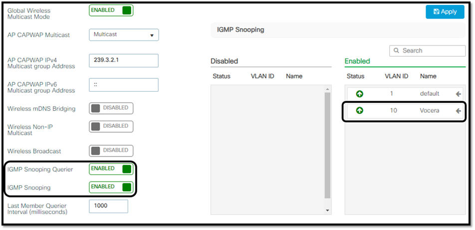
it is recommended to enable IGMP snooping on the WLC. This ensures that the WLC maintains awareness of which Vocera badges have expressed interest in joining the multicast stream initiated by the badge that started the broadcast command. To further optimize multicast efficiency, both IGMP snooping and the IGMP querier function must be enabled. Additionally, IGMP must be explicitly enabled for the VLAN assigned to the badges.
In the GUI:
- To configure the capwap multicast navigate to Configuration > Services > Multicast. Enable IGMP Snooping, IGMP Snooping Querier and add the desired VLANs to the IGMP Snopping enabled box, and click Apply.
In the CLI:
C9800#conf t
C9800(config)#ip igmp snooping
C9800(config)#ip igmp snooping vlan <vlan-id>
C9800(config)#ip igmp snooping querier
Verify
After configuring multicast on the WLC, verify the multicast mode in use that CAPWAP multicast traffic can be forwarded as expected. use the command show wireless multicast to view the CAPWAP multicast status on the controller.
C9800#show wireless multicast
Multicast: Enabled
AP CAPWAP Multicast: Multicast
AP CAPWAP IPv4 Multicast group Address: 239.3.2.1
To verify communication between the AP and the WLC through the CAPWAP multicast tunnel, use the show ap multicast mom command. In the command output, review the Status column. The desired result is for the status to display as UP.
C9800# show ap multicast mom
AP Name MOM-IP TYPE MOM- STATUS
------------------------------------------------------
AP9120 IPv4 Up

Note: The Cisco IOS® MOM-STATUS displays as "UNKNOWN" for certain Cisco IOS-based Access Point models. This occurs because these APs do not send the MoM payload to the controller. The affected models include: Cisco Aironet 1702i Access Point, Cisco Aironet 3702i/3702e Access Point, Cisco IW3702 Access Point. For more details, refer CSCwd12261 
If the status is displayed as “DOWN”, the issue is most commonly related to multicast routing. Troubleshooting must begin by verifying multicast connectivity between the AP and the WLC. In deployments where the AP and WLC reside in different VLANs, this verification is specially critical, as additional configuration is required to allow multicast traffic to traverse subnet boundaries.
On the Layer 3 device that serves as the gateway for both the WLC and the AP subnets, multicast routing must be enabled globally with the ip multicast-routing command. In addition, Protocol Independent Multicast (PIM) must be configured on each interface acting as the default gateway for the AP and WLC VLANs by applying the ip pim sparse-dense-mode command:
Router#sh run all | sec multicast-routing|inrterface x|inrterface y
ip multicast-routing
!
interface X
ip pim sparse-dense-mode
!
interface Y
ip pim sparse-dense-mode
!
Note: PIM sparse-dense-mode was used in this example for simplicity. However, it is important to note that the PIM mode can vary depending on the network requirements.
Review the multicast routing functionality on the L3 device. To confirm that the CAPWAP multicast traffic from the WLC to the AP is being forwarded, run the show ip mroute x.x.x.x command, where x.x.x.x represents the multicast address assigned to CAPWAP multicast on the WLC.
Router#show ip mroute 239.3.2.1
(*, 239.3.2.1), 00:05:46/stopped, RP 0.0.0.0, flags: DCL
Incoming interface: Null, RPF nbr 0.0.0.0
Outgoing interface list:
GigabitEthernet0/2, Forward/Sparse-Dense, 00:04:28/stopped
GigabitEthernet0/1, Forward/Sparse-Dense, 00:05:46/stopped
(192.3.2.1, 239.3.2.1), 00:02:03/00:02:56, flags: LT
Incoming interface: GigabitEthernet0/1, RPF nbr 0.0.0.0
Outgoing interface list:
GigabitEthernet0/2, Forward/Sparse-Dense, 00:02:03/stopped
Note: The output shows that the default gateway is receiving the multicast address 239.3.2.1 (CAPWAP multicast address) from 192.3.2.1 (WLC’s IP address) on GigabitEthernet0/1 and is then forwarding it to GigabitEthernet0/2, which are the interfaces assigned to the subnets of the APs.
Review the status of the IGMP snooping on the WLC using one of the sh run all | sec igmp snooping or show ip igmp snooping commands:
C9800#sh run all | sec igmp snooping
ip igmp snooping querier
ip igmp snooping
C9800#show ip igmp snooping
Global IGMP Snooping configuration:
-------------------------------------------
IGMP snooping : Enabled
Vlan 10:
--------
IGMP snooping : Enabled

Caution: You must be cautious when using IGMPv3 with switches that are enabled for IGMP snooping. The IGMPv3 messages are different from the messages used in IGMP Version 1 (IGMPv1) and Version 2 (IGMPv2). If your switch does not recognize IGMPv3 messages, the hosts do not receive traffic when IGMPv3 is used.
IGMPv3 devices do not receive multicast traffic in either cases: When IGMP snooping is disabled. When IGMPv2 is configured on the interface. It is recommended to enable IGMPv3 on all intermediate or other Layer 3 network devices. Primarily, on each subnet used by multicast devices including controller and AP subnets.
When a Vocera broadcast is initiated, the Badges send an IGMP join message being forwarded to the WLC. To confirm that the WLC is properly receiving these IGMP join requests, use the show wireless multicast group summary command. The desired output must display a multicast group address within the reserved Vocera multicast range and VLAN associated with the Vocera Badges.
C9800#show wireless multicast group summary
IPv4 groups
-------------
MGID Group Vlan
-----------------------------------------
4160 230.230.0.1 10
IPv6 groups
-------------
MGID Group Vlan
----------------------------------------------------
C9800#
To identify the specific Vocera badges that have subscribed to a given broadcast stream on the WLC, run the show wireless multicast group X.X.X.X vlan Y command. In this command, replace X.X.X.X with the Vocera multicast address assigned by the Vocera server (as indicated in the output of the previous verification command), and replace Y with the VLAN to which the badge is connected.
C9800#show wireless multicast group 230.230.0.1 vlan 10
Group : 230.230.0.1
Vlan : 10
MGID : 4160
Client List
-------------
Client MAC Client IP Status
---------------------------------------------------------------
aaaa.bbbb.cccc 10.10.0.1 MC_ONLY
Once all configuration steps have been completed and the WLC is confirmed to be receiving IGMP join requests from the Vocera badges, the WLC forwards the Vocera broadcast by encapsulating it within a CAPWAP multicast tunnel directed toward the APs, the APs receive the CAPWAP multicast, de-encapsulate the Vocera broadcast packets, and forward them to the Vocera badges that have requested to join the stream.
References
 Feedback