Cisco Wireless Vocera Deployment Guide
Available Languages
Bias-Free Language
The documentation set for this product strives to use bias-free language. For the purposes of this documentation set, bias-free is defined as language that does not imply discrimination based on age, disability, gender, racial identity, ethnic identity, sexual orientation, socioeconomic status, and intersectionality. Exceptions may be present in the documentation due to language that is hardcoded in the user interfaces of the product software, language used based on RFP documentation, or language that is used by a referenced third-party product. Learn more about how Cisco is using Inclusive Language.
This document provides design considerations, deployment guidelines, and best practices for the implementation of Vocera badges over Cisco wireless LAN solutions.
It includes Vocera device and Cisco wireless LAN settings for the recommended environment and RF characteristics.
We have consolidated all the best practices on wireless infrastructure and device/platform configuration for an optimal Vocera badge deployment.
Cisco recommends that you have knowledge of these topics:
● Cisco Catalyst 9800 Series Wireless Controller (WLC) configuration
● Multicast on a WLC
● Wireless RF characteristics
● Basic understanding of how network requirements are gathered and RF surveys are conducted
Recommended Cisco IOS XE Software releases
This section provides guidance on the most reliable Cisco IOS XE software for Catalyst WLCs. Refer the below link for recommended software releases, https://www.cisco.com/c/en/us/support/docs/wireless/catalyst-9800-series-wireless-controllers/214749-tac-recommended-ios-xe-builds-for-wirele.html
Vocera B3000n Communication Badge
Delivering a secure, integrated, and intelligent communication solution for customers, the Vocera B3000n Communication Badge builds upon the success of the B3000 Communication Badge and is a key component of the Vocera Communication System created to deliver secure, integrated, and intelligent communication. The Vocera badge has been designed from the ground up to meet the requirements of highly mobile workers who need to stay connected while keeping their hands free to perform their regular job duties. Using an enterprise-class Wi-Fi network, the Vocera badge delivers hands-free, real-time voice communication between users whenever needed.
The wearable Vocera badge weighs less than 2 ounces, allowing users to keep their hands free without the burden of carrying a smartphone. With a highly durable design, the Vocera badge is built to withstand the rigors of challenging environments. Acoustic tuning using four microphones and advanced noise reduction technology greatly improve the hands-free audio experience for users while providing greater accuracy for voice recognition.
Features overview:
● The dual-band radio permits the B3000n to use both the 2.4-GHz and 5-GHz Wi-Fi spectrum. 5 GHz is less susceptible to noise and interference from other radio devices, leading to higher voice quality and better voice recognition.
● The B3000n contains an illuminated halo around the call button; this halo provides a visual indication of the badge call status. It glows green when on an active call and pulses amber when on Do Not Disturb or on hold. The illuminated halo can also be used to indicate when text messages are waiting to be read.
● A large, front-facing speaker provides hands-free audio, enabling users to clearly hear the conversation without having to hold the Vocera badge in their hands.
● Four microphones and integrated Acoustic Noise Reduction (ANR) reduce background conversations and noise interference to improve speech recognition in noisy environments.
● Multiuser operation (shared device) permits a Vocera badge to be passed to another user at the end of a shift, allowing the new user to log in to the Vocera system from the Vocera badge and immediately begin using it.
For more information, refer to the Vocera B3000n Communication Badge data sheet at https://www.vocera.com/resource/data-sheets/vocera-b3000n-communication-badge
The pace, complexity, and unpredictability of the hospital environment cause care team members to multitask and reprioritize constantly. Care teams need to field multiple interruptions and shifting variables in real time while still delivering the best possible patient care. They need tools that help them to identify priorities, access information, and communicate effectively—yet allow them to keep both hands free so they can communicate and access and share information without interrupting patient care. It’s often impractical and inefficient for clinicians to manage a smartphone when providing hands-on patient care.
Imagine neonatologists and nurses caring for sick babies in a closed unit: Both hands are engaged with tiny patients, and infection control is paramount. The need to communicate across obstructed lines of sight means stopping to use a phone and then washing their hands before care can continue. Now imagine a hundred such moments for those nurses and doctors, every day.
It’s time to change the conversation.
Meet the Vocera Smartbadge.
Designed to enable clinician agility and accelerate patient care, the Vocera Smartbadge is an entirely new approach to patient-centered healthcare communication. Leveraging our nearly two-decade track record of responding to the challenges hospital clinicians face every day, the Smartbadge redefines and revolutionizes the way care teams connect, collaborate, and act.
Situational awareness. In sync.
The Smartbadge is powered by the Vocera Platform, which enables data to be aggregated from most clinical and operational systems used in hospitals today. The Smartbadge allows patient information from those systems to be presented in parallel with notifications to enable real-time situational awareness and help reduce interruption fatigue.
Bring the care team in. Even when they’re out.
Just say a name, a role, or a group name to connect instantly with care team members inside or outside the hospital. There’s no need to remember phone numbers or keep track of who’s on call. The Smartbadge responds to more than 100 voice commands through an optimized speech-recognition engine.
You can send broadcast messages easily to rapid-response groups, such as code blue and sepsis-response teams. A dedicated panic button allows you to summon help instantly.
For more information, refer to the Vocera Smartbadge Solution Brief, https://www.vocera.com/resource/solution-briefs/vocera-smartbadge
The Vocera badge uses both unicast and multicast packet delivery to provide several key features that make up this complete solution. Here are four of the essential features that rely on proper packet delivery, with basic information on how each feature uses the underlying network for delivery and functionality.
Badge-to-badge communications: When one Vocera user calls another user, the badge first contacts the Vocera server, which looks up the IP address of the badge of the callee and contacts the badge user to ask the user if they can take a call. If the callee accepts the call, the Vocera server notifies the calling badge of the IP address of the callee badge to set up direct communication between the badges with no further server intervention. All communication with the Vocera server uses the G.711 codec, and all badge-to-badge communication uses a Vocera proprietary codec.
Badge telephony communication: When a Vocera telephony server is installed and set up with a connection to a PBX, a user can call internal extensions from the PBX or outside telephone lines. Vocera allows users to make calls either by saying the numbers (five, six, three, two) or by creating an address book entry in the Vocera database for the person or function at that number (for example, pharmacy, home, pizza). The Vocera server determines the number that is being called, either by intercepting the numbers in the extension or by looking the name up in the database and selecting the number. The Vocera server then passes that information to the Vocera telephony server, which connects to the PBX and generates the appropriate telephony signaling (for example, Dual-Tone Multifrequency [DTMF]). All communication between the badge and Vocera server and between the Vocera server and Vocera telephony server use the G.711 codec over unicast User Datagram Protocol (UDP).
Vocera broadcast: A Vocera badge user can call and communicate to a group of Vocera badge wearers at the same time by using the Broadcast command. When a user broadcasts to a group, the user's badge sends the command to the Vocera server, which then looks up the members of a group, determines which members of the group are active, assigns a multicast address to use for this broadcast session, and sends a message to each active user’s badge instructing it to join the multicast group with the assigned multicast address.
Badge location function: The Vocera server keeps track of the access point to which each active badge is associated, as each badge sends a 30-second keepalive to the server with the associated basic service set identifier (BSSID). This allows the Vocera system to roughly estimate the location of a badge user. This function has a relatively low degree of accuracy because a badge might not be associated to the access point to which it is closest.
Vocera infrastructure planning
The Vocera Infrastructure Planning Guide white paper describes the site survey minimum requirements, which show that the badge should have a minimum received signal strength of -65 dBm, a signal-to-noise ratio (SNR) greater than 25 dB, and proper access point overlap and channel separation. Although the badges use an omnidirectional antenna similar to that of the notebook that would be used for a site survey, a notebook does not mimic the behavior of the badge very well, given the wearers’ effects on signal strength. Due to this unique requirement and the behavior of the transmitting device, the use of the Cisco architecture and Radio Resource Management (RRM) is ideal to make sure there are no unusual Radio Frequency (RF) site characteristics.
Successful and smooth handoffs can occur only if the coverage cells of adjacent access points overlap. For example, a person who is moving around while wearing a badge must be able to stay connected to the current access point while moving into the coverage area of an adjacent access point to ensure that a handoff can occur without packets being dropped.
A properly designed wireless network must provide cells with overlapping coverage on noninterfering channels while simultaneously maintaining proper cell separation among access points using the same channel. Adequate cell overlap is required for smooth Basic Service Set (BSS) transitions.
The boundaries of access point coverage cells can change in real time as people and objects move around in the network environment. Some access points attempt to accommodate this situation by adjusting their power output dynamically.
Overlapping cells on the same channel result in:
● Interference and dropped packets
● Shared network bandwidth
● Increase in noise flow
● Decrease in SNR
Vocera recommends a site survey for voice to prepare for the performance requirements of the badges and access points. The survey provides an opportunity to tune the access points and understand the roaming characteristics and different coverage requirements.
Vocera badges operate at a low power and require a voice-grade network capable of transmitting human voice. All mobile battery clients operate at a lower power than the maximum transmit (TX) power of an access point.
Before conducting the survey, perform the following prerequisites:
● Authenticate and connect the badges to the corporate voice SSID so that you can test call quality and roaming by playing the welcome tutorial or an in-a-call session.
● Test multicast functionality by initiating a broadcast call. If the chime is heard followed by no audio at the recipient badges, the site network administrators must be notified that multicast is not configured properly in the wired or wireless network.
● Test the TX power of the access points to be sure it does not exceed Vocera’s required TX settings. (Ensure that the TX power of your access points falls within the maximum and minimum power recommended.)
Table 1. Maximum and minimum recommended transmit
| Device and frequency |
Maximum power |
| B3000n (2.4 GHz) |
Max 17dBm (50 mW) and Min 12dbm (16 mW) |
| B3000n (5 GHz) |
Max 16 dBm (40 mW) and Min 13 dbm (20 mW) |
| V5000 (5 GHz) |
Max 17 dBm (50 mW) and Min 13 dbm (20 mW) |
Capacity refers to the maximum number of device-to-device calls a specific access point can support simultaneously.
Capacity planning is an important aspect of a Vocera deployment. An access point is flooded when the number of calls it is processing exceeds its capacity. High-traffic areas may require more access points than low-traffic areas to prevent flooding.
For example, you may need to provide additional access points in places such as breakrooms or nursing stations if device users frequent these areas. Monitor user traffic patterns when you update your site survey to accommodate the Vocera system.
A Vocera usage pattern is not like that of a conventional telephone. Vocera calls are typically brief, meaning there is less probability of many users being on calls simultaneously and exceeding the capacity of an access point.
Introducing additional access points to a network can create new problems, such as choppy audio due to interference with existing access points.
The following table displays the packet characteristics per Vocera device.
Table 2. Bandwidth used per device
| Vocera version |
Device |
Codec |
Bandwidth used for sound |
Packet interval |
Packets per second |
| VS 4.4.x |
B3000n/B3000 |
G.711 |
64 Kbps |
36 ms |
27.8 |
| VS 5.x |
B3000n/B3000/V5000 |
G.711 |
64 Kbps |
20 ms |
50 |
Important: It is possible to achieve more calls per access point than shown in the table, but the voice quality will degrade, resulting in choppy audio.
The following table shows the recommended maximum number of device and calls per AP with acceptable voice quality supported by a wireless test network.
Table 3. Maximum calls and devices per access point
| Wireless band |
Device |
Max calls per AP |
Max devices on calls per AP |
| 2.4 GHz |
B3000n |
8 |
14 |
| 5 GHz |
B3000n, B3000, V5000 |
18 |
30 |
Multicasting is a method of sending messages or data to many clients at the same time using IP multicast group addresses. Multicasting is more efficient than unicasting.
A badge can send one multicast packet to many receivers instead of sending one copy of the unicast packet to each receiver. Vocera uses multicast transmissions to provide broadcasts and Push-To-Talk (PTT) conferences. Vocera multicast features can be configured to cross subnet boundaries.
The Vocera broadcast and instant conference PTT features use multicast to forward IP datagrams to a multicast group within a single subnet for urgent broadcast commands, Virtual Multipoint Interface (VMI) broadcasts, and broadcasts from a phone. If your network uses Internet Group Management Protocol (IGMP) to manage multicast traffic between IP hosts across an IP subnet boundary, you may configure all badges to support IGMP broadcasts.
By default, the B3000 uses IGMP version 2, the B3000n uses IGMP versions 2 and 3, and the V5000 uses IGMP version 3.
Note: You must be cautious when using Internet Group Management Protocol version 3 (IGMPv3) with switches that are enabled for IGMP snooping. The IGMPv3 messages are different from the messages used in IGMP Version 1 (IGMPv1) and Version 2 (IGMPv2). If your switch does not recognize IGMPv3 messages, the hosts do not receive traffic when IGMPv3 is used.
IGMPv3 devices do not receive multicast traffic in either case:
● When IGMP snooping is disabled.
● When IGMPv2 is configured on the interface.
It is recommended to enable IGMPv3 on all intermediate or other Layer 3 network devices. Primarily, on each subnet used by multicast devices including controller and AP subnets. https://www.cisco.com/c/en/us/td/docs/wireless/controller/9800/17-6/config-guide/b_wl_17_6_cg/m-vewlc-multicast-cg.html
Multicast in wireless deployment
Understanding multicast within a Control and Provisioning of Wireless Access Points (CAPWAP) deployment is necessary to deploy the Vocera broadcast function. This document later covers the essential steps to enable multicast within the controller-based solution. There are currently two delivery methods that the Catalyst 9800 Series controller uses to deliver multicast to the clients:
● Multicast-unicast
● Multicast-multicast
The multicast-unicast delivery method creates a copy of every multicast packet and forwards it to every access point. When a client sends a multicast IGMP/MLD join to the wireless LAN, the access point forwards this join through the CAPWAP tunnel to the controller. The controller bridges this multicast join onto its directly connected LAN connection that is the default Virtual LAN (VLAN) for the associated Wireless LAN (WLAN) of the client. When an IP multicast packet arrives from the network to the controller, the controller replicates this packet with a CAPWAP header for each access point that has a client within the wireless domain that has joined this specific group. When the source of the multicast is also a receiver within the wireless domain, this packet is also duplicated and forwarded back to the same client that sent the packet.
For Vocera badges, this is not the preferred method of multicast delivery within the CAPWAP controller solution. The unicast delivery method works with small deployments. However, due to the considerable overhead on the WLC, this is never the recommended multicast delivery method.
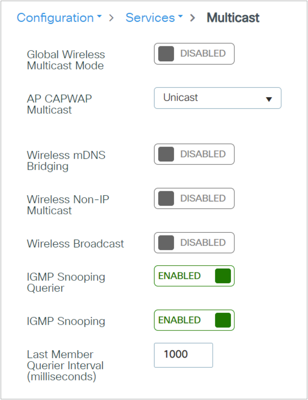
Use the following command to check that the mode is set to unicast:
C9800#show wireless multicast
| Multicast: Disabled AP CAPWAP Multicast: Unicast Wireless Broadcast: Disabled Wireless Multicast non-ip-mcast: Disabled Wireless Multicast link-local: Enabled |
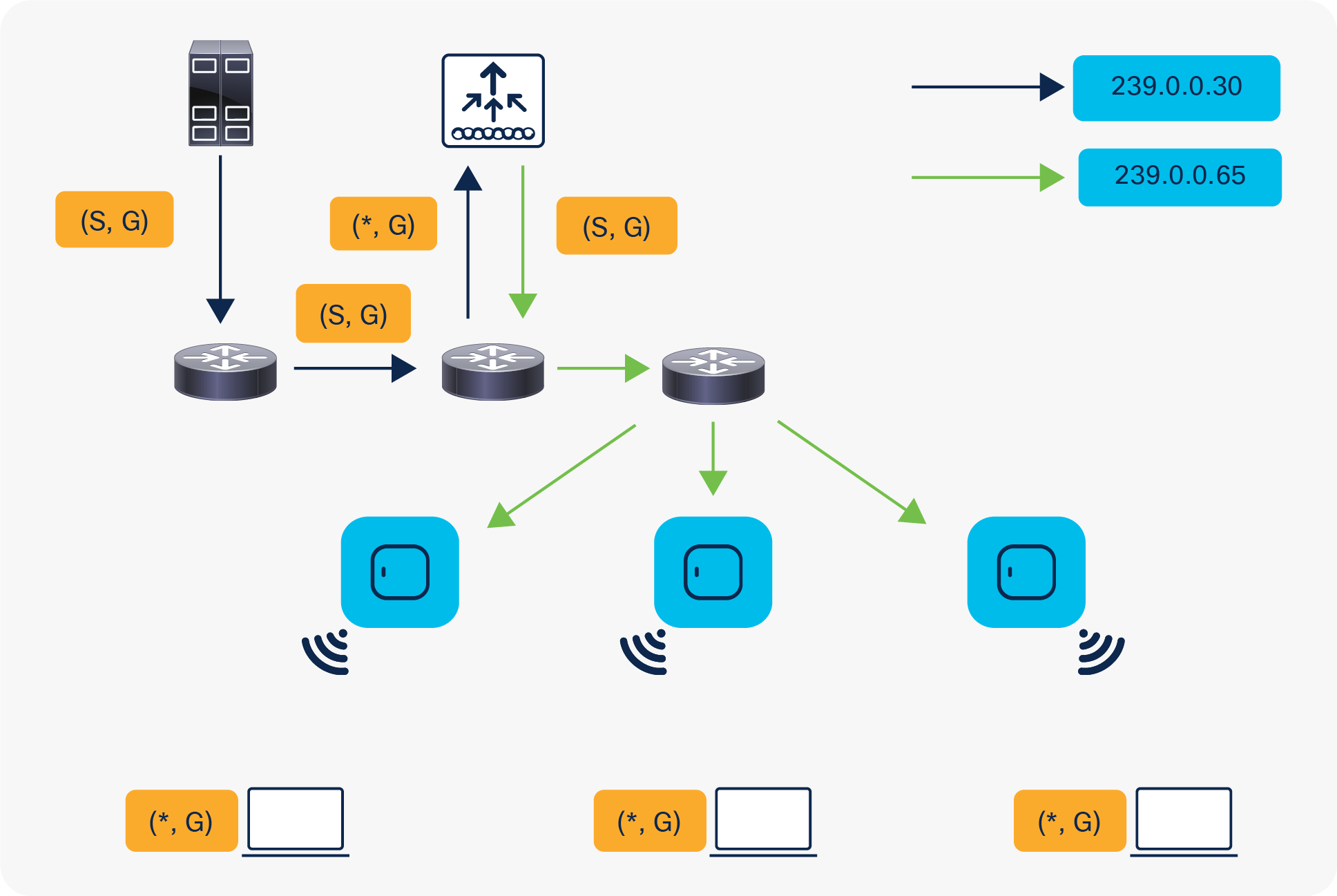
The multicast-multicast delivery method does not require the controller to replicate each multicast packet received. The controller is configured for an unused multicast group address that each access point becomes a member of.
In Figure 1, the multicast group defined from the WLC to the access point is 239.0.0.65. When a client sends a multicast join to the WLAN, the access point forwards this join through the CAPWAP tunnel to the controller. The controller forwards this link-layer protocol onto its directly connected LAN connection that is the default VLAN for the associated WLAN of the client. The router that is local to the controller then adds this multicast group address to that interface for forwarding ((*,G)). In Figure 1, the example multicast join was sent to the multicast group 239.0.0.30. When the network now forwards multicast traffic, the multicast address of 239.0.0.30 is forwarded to the controller. The controller then encapsulates the multicast packet into a CAPWAP multicast packet addressed to the multicast group address (239.0.0.65 in the figure) that is configured on the controller and forwarded to the network. Each access point on the controller receives this packet as a member of the controller multicast group. The access point then forwards the clients’ or servers’ multicast packet (239.0.0.30) as a broadcast to the WLAN/SSID identified within the CAPWAP multicast packet.
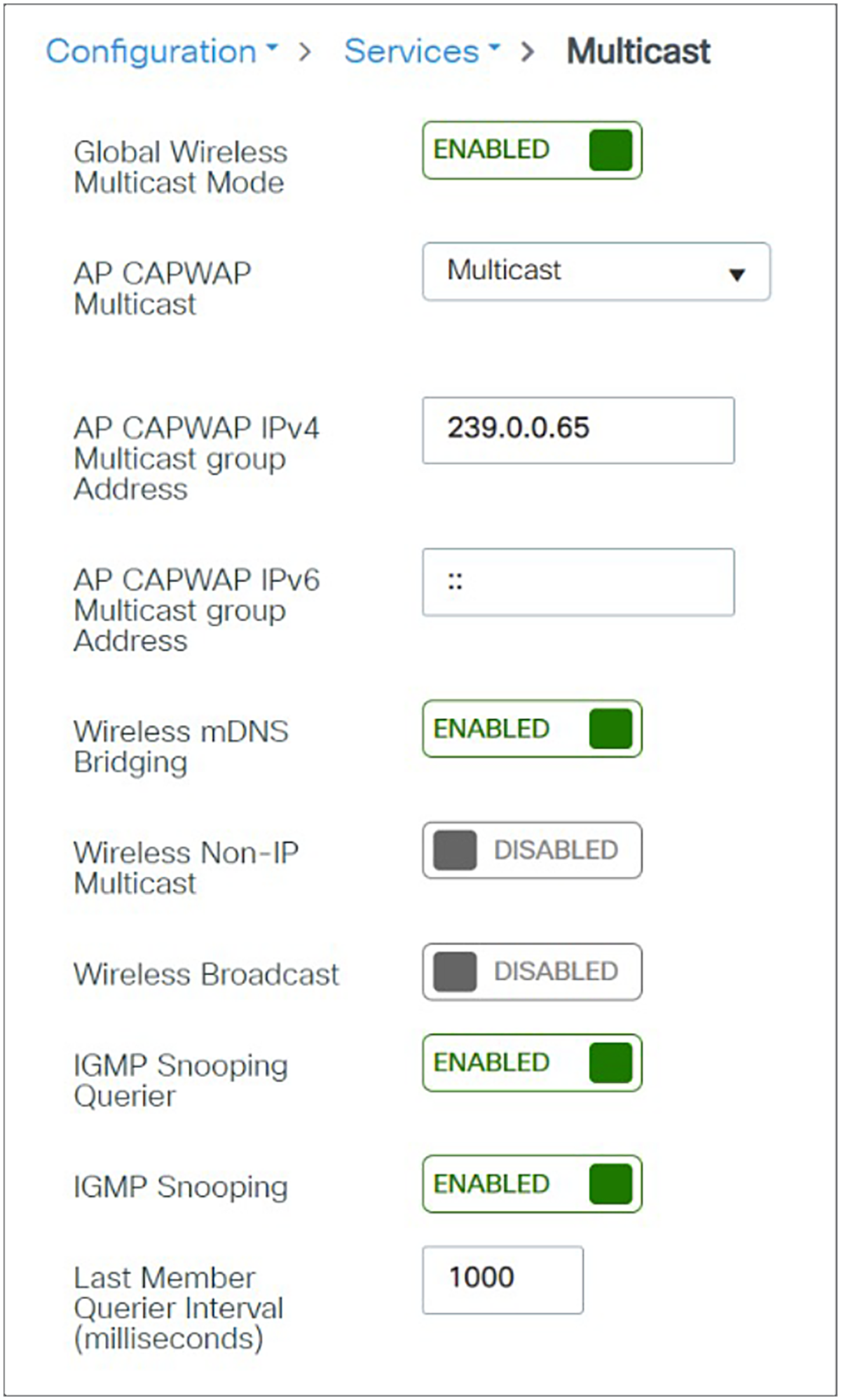
Use the following command to verify the multicast mode:
C9800#show wireless multicast
| Multicast: Enabled AP CAPWAP Multicast: Multicast AP CAPWAP IPv4 Multicast group Address: 239.0.0.65 AP CAPWAP IPv6 Multicast group Address: :: Wireless Broadcast: Disabled Wireless Multicast non-ip-mcast: Disabled Wireless Multicast link-local: Enabled |
WLC-AP Multicast Status:
Cisco Catalyst 9800 Series Wireless Controller initiates a ping request that passes through the CAPWAP multicast tunnel onto the CAPWAP multicast receiver, which is the AP. In response, the AP pings the packets for CAPWAP multicast group IP address and sends back the response to the controller. You can view the statistics on the AP for transmitted and received traffic to analyse the data that are sent and received through the multicast tunnel. Alternatively, you can also verify by enhancing the existing statistics on the AP for transmitted and received traffic to explicitly list the joins, leaves, data packets transmitted and received through the multicast tunnel.
To confirm if the APs receive multicast to multicast (mom) traffic sent by the controller, use the following command,
| C9800#show ap multicast mom AP Name MOM-IP TYPE MOM-STATUS --------------------------------------------- Cxxxxxxx IPv4 Up |
Multicast group join
To confirm the APs, join to the multicast group by use the following command in the Switch,

To confirm the WLC snoops the Multicast query, use the following command at WLC,

Cisco FlexConnect access points allow the local termination of WLANs at the network edge rather than being centrally switched to the WLC, and the multicast behavior is controlled at that edge. If a FlexConnect WLAN is centrally switched and multicast is enabled on that WLC, multicast is delivered to that FlexConnect WLAN and the CAPWAP multicast group is allowed to extend to the FlexConnect network location.
For Locally switched network, Client is bridged at AP and receives Multicast over locally assigned VLAN ID. The multicast group configurations at the WLC does not have any impact in locally switched network as the AP and switched attached will handle the client multicast traffic.
Internet Group Management Protocol (IGMP)
IP networks use IGMP and Protocol Independent Multicast (PIM) to manage multicast traffic across Layer 3 boundaries. When IGMP is enabled on your network, routers and other network devices use it to determine which hosts in the domain are interested in receiving multicast traffic.
The Vocera server assigns a multicast address to each broadcast session. The device registers to receive the stream and joins the group by sending an IGMP report to the upstream router. The router then adds that group to the list of multicast groups that should be forwarded on to the local subnet. IGMP allows the device to inform the router that it is interested in receiving a particular multicast stream. When a host no longer wants to receive multicast traffic, it sends the router an IGMP Leave message.
If IGMP is enabled on your network and you want to broadcast across subnets, you must also set the B3.BroadcastUsesIGMP True property on the badge. Enabling this property allows a badge to register its membership in the appropriate multicast group to receive multicast traffic from other badges, as well as from another subnet. Vocera broadcast is implemented as IP multicast. If broadcast commands must cross a subnet, IGMP must be supported on the switch, IP multicast routing on your router, and PIM on your VLANs.
Note: For B3000n and B3000 badges, the Broadcast Uses IGMP property is enabled by default.
When the badge property V5.ForceIGMPVersion is set, and if the Vocera Smartbadge is configured to use IGMP version 3, but your network supports only IGMP version 2, the Smartbadge negotiates down to IGMP version 2 and uses that with the network.
Note: You must be cautious when using Internet Group Management Protocol version 3 (IGMPv3) with switches that are enabled for IGMP snooping. The IGMPv3 messages are different from the messages used in IGMP Version 1 (IGMPv1) and Version 2 (IGMPv2). If your switch does not recognize IGMPv3 messages, the hosts do not receive traffic when IGMPv3 is used.
IGMPv3 devices do not receive multicast traffic in either case:
● When IGMP snooping is disabled.
● When IGMPv2 is configured on the interface.
It is recommended to enable IGMPv3 on all intermediate or other Layer 3 network devices. Primarily, on each subnet used by multicast devices including controller and AP subnets. https://www.cisco.com/c/en/us/td/docs/wireless/controller/9800/17-6/config-guide/b_wl_17_6_cg/m-vewlc-multicast-cg.html
For more information, refer to the Vocera Badge Configuration Guide, https://pubs.vocera.com/vs_infrastructure/Production/docs/InfrastructureGuide.pdf
Internet Group Management Protocol (IGMP) snooping
IGMP snooping is a method wherein switches, access points, and controllers can listen in on IGMP messages between hosts and routers.
The network switches will intelligently forward multicast traffic only to those ports that have joined the multicast group. IGMP snooping can be configured on network switches and access points.
To enable multicast features across subnet boundaries, perform the following steps:
1. Enable IGMP snooping for all switches, access points, and controllers. For example, enable it on the switches and access points on each subnet used by the badge.
2. Enable IP multicast routing on all intermediate routers or other network devices on the Vocera subnets.
3. Enable PIM sparse-dense mode on all VLANs that the voice traffic will traverse.
4. Set the Broadcast Uses IGMP property to True on all badges.
For more information, refer to the Vocera Badge Configuration Guide, https://pubs.vocera.com/vs_infrastructure/Production/docs/InfrastructureGuide.pdf
Catalyst 9800 Series configuration
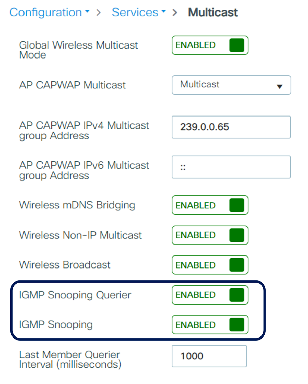
Make sure both IGMP snooping and the IGMP querier are enabled for Vocera deployment in the Catalyst 9800 Series as follows:
Cisco introduces an IGMP query to allow users to roam at Layer 2 by sending a general IGMP query when this occurs. The client then responds with the IGMP group that they are a member of, and this is bridged to the wired network as described earlier in this document. When a client roams to a controller that does not have Layer 2 connectivity, or a Layer 3 roam, synchronous routing is added for multicast source packets. When a client that has completed a Layer 3 roam sources a multicast packet from the wireless network, the foreign controller encapsulates this packet in Ethernet over IP (EoIP or CAPWAP) in the IP tunnel to the anchor controller. The anchor controller then forwards that packet to the wireless clients that are locally associated, as well as bridging it back to the wired network, where it is routed using normal multicast routing methods.
Multicast traffic flow in Layer 3 mobility
A single controller is the most straightforward deployment scenario. It allows you to deploy the Vocera badge solution with few deployment concerns. Your network must be enabled for IP multicast routing only to allow the access points to receive the CAPWAP multicast packets. If required, you can limit network multicast complexity by configuring all routers and switches with the controllers multicast group.
With multicast configured globally on the controller, the proper SSID, security settings, and all the access points registered, the Vocera badge solution, and all its functions, operates as expected. With the Vocera broadcast function, a user roams and the multicast traffic follows as expected. No extra settings are required to allow this solution to function properly.
When a Vocera badge sends a multicast message, as it does with a Vocera broadcast, it is forwarded to the controller. The controller then encapsulates this multicast packet within a CAPWAP multicast packet. The network infrastructure forwards this packet to every access point that is connected to this controller. When the access point receives this packet, it then looks at the CAPWAP multicast header to determine which WLAN/SSID it should broadcast this packet to.
When a client that is listening to the multicast groups roams from one controller to another, the first controller transmits all the multicast group information for the listening client to the second controller. As a result, the second controller can immediately create the multicast group information for the client. The second controller sends the IGMP reports to the network for all multicast groups to which the client was listening. This process aids in the seamless transfer of multicast data to the client.
With the Vocera broadcast function, a client that roams to another controller as a Layer 2 roam receives a general IGMP query immediately after authentication. The client should then respond with the interested groups, and the new controller will then bridge this client to the locally connected switch. This allows the advantages of IGMP and Cisco Group Management Protocol on your upstream switches.
You can create additional badge SSIDs and Layer 2 domains for separate badge networks as long as your network is configured to pass multicast traffic appropriately. Also, each Vocera Layer 2 broadcast domain created must exist everywhere a controller is connected to the network so as not to break multicast.
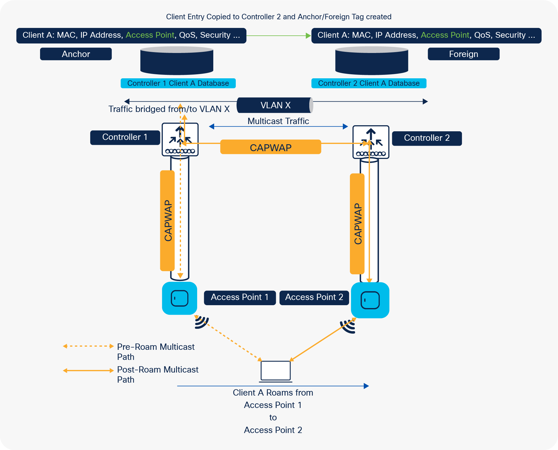
Multi-controller deployment – Layer 3
Layer 3 roaming environments are a little more complex in this respect. Layer 3 roaming is like Layer 2 roaming in that the controllers exchange mobility messages on the client roam. However, instead of moving the client database entry to the new controller, the original controller marks the client with an “Anchor” entry in its own client database. The database entry is copied to the new controller client database and marked with a “Foreign” entry in the new controller. The roam remains transparent to the wireless client, and the client maintains its original IP address.
If the listening client roams to a controller in a different subnet, the multicast packets are tunneled to the anchor controller of the client. The anchor then forwards the multicast packets to the infrastructure switch.
As explained in the previous section, when a client performs a Layer 3 roam, synchronous routing is added for multicast source packets. When a client, who has completed a Layer 3 roam sources a multicast packet from the wireless network, the foreign controller encapsulates this packet in the Mobility messages (EOIP or CAPWAP) in IP tunnel to the Anchor controller. The anchor controller then forwards that to the wireless clients locally associated as well as bridge this back to the wired network where it is routed using normal multicast routing methods.
Multicast traffic flow in inter-controller roaming
If the user experience voice quality deterioration during roaming or after roaming, there could be multiple factors involved, refer the suggestions in Common Roaming Issues section to identify the cause of the problem.
Deployment challenges and recommendations
Wireless IP telephony networks require careful RF planning. A thorough voice site survey is often required to determine the proper levels of wireless coverage and to identify sources of interference. Access point placement and antenna selection can be greatly eased with the help of the results of a valid voice site survey. The most important consideration is the transmit power of the wireless phone or badge. Ideally the device will learn the transmit power of the access point and adjust its transmit power to that of the access point.
Although most wireless networks today are deployed after an extensive RF site survey, the deployments are designed with data service in mind as well. Voice over WLAN (VoWLAN) phones are likely to have different roaming characteristics and different coverage requirements than those of a typical WLAN adapter for a mobile client such as a laptop. Therefore, an additional site survey for voice is often recommended to prepare for the performance requirements of multiple VoWLAN clients. This additional survey gives the opportunity to tune the access points to ensure that the VoWLAN badges have enough RF coverage and bandwidth to provide proper voice quality.
For additional information on RRM and RF design considerations, refer to the C9800 Radio Resource Management Deployment Guide, available at https://www.cisco.com/c/en/us/td/docs/wireless/controller/technotes/8-8/b_C9800_rrm_dg.html.
Many aspects of building construction are unknown or hidden from the site survey, so you might have to acquire that information from other sources (such as architectural drawings). Some examples of typical construction methods and materials that affect the range and coverage area of access points include metallic film on window glass, leaded glass, steel-studded walls, cement floors and walls with steel reinforcement, foil-backed insulation, stairwells and elevator shafts, plumbing pipes and fixtures, and many others.
Various types of inventories can affect RF range, particularly those with high steel or water content. Some items to watch for include cardboard boxes, pet food, paint, petroleum products, engine parts, and so forth.
Make sure you perform a site survey at peak inventory levels or at times of highest activity. A warehouse at a 50% stocking level has a very different RF footprint than the same warehouse at an inventory level of 100%.
Similarly, an office area after hours (without people) has a different RF footprint than the same area during the day, when it is full of people. Although many parts of the site survey can be conducted without full occupation, it is essential to verify the site survey and tweak key values during a time when the location is occupied. The higher the utilization requirements and density of users, the more important it is to have a well-designed diversity solution. When more users are present, more signals are received on each user's device. Additional signals cause more contention, more null points, and more multipath distortion. Diversity on the access point (antennas) helps minimize these conditions.
Keep in mind these guidelines when you conduct a site survey for a typical office building:
● Elevator shafts block and reflect RF signals.
● Supply rooms with inventory absorb signals.
● Interior offices with hard walls absorb RF signals.
● Breakrooms (kitchens) can produce 2.4-GHz interference via microwave ovens.
● Test labs can produce 2.4-GHz or 5-GHz interference, creating multipath distortion and RF shadows.
● Cubicles tend to absorb and block signals.
● Conference rooms require high levels of access point coverage because they are areas of high utilization.
Extra precaution must be administered when you survey multi-floor facilities. Access points on different floors can interfere with each other as easily as access points located on the same floor. It is possible to use this behavior to your advantage during a survey. Using higher-gain antennas, it might be possible to penetrate floors and ceilings and provide coverage to floors above as well as below the floor where the access point is mounted. Be careful not to overlap channels between access points on different floors or access points on the same floor. In multitenant buildings, security concerns might require the use of lower transmission powers and lower-gain antennas to keep signals out of neighbouring offices.
The survey process for a hospital is much the same as that for an enterprise, but the layout of a hospital facility tends to differ in these ways:
● Hospital buildings tend to go through many reconstruction projects and additions. Each additional construction is likely to have different construction materials with different levels of attenuation.
● Signal penetration through walls and floors in patient areas is typically minimal, which helps create microcells and multipath variations.
● The need for bandwidth increases with the increasing use of WLAN ultrasound equipment and other portable imaging applications. The need for bandwidth increases with the addition of wireless voice as well.
● Healthcare cells are small, and seamless roaming is essential, especially with voice applications.
● Cell overlap can be high, and so can channel reuse.
● Hospitals can have several types of wireless networks installed. This includes 2.4-GHz non-802.11 equipment. This equipment can cause contention with other 2.4-GHz networks.
● Wall-mounted diversity patch antennas and ceiling-mounted diversity omnidirectional antennas are popular, but keep in mind that diversity is required.
Warehouses have large open areas that often contain high storage racks. Many times, these racks reach almost to the ceiling, where access points are typically placed. Such storage racks can limit the area that the access point can cover. In these cases, consider placing access points on other locations besides the ceiling, such as side walls and cement pillars. Also consider the following factors when you survey a warehouse:
● Inventory levels affect the number of access points needed. Test coverage with two or three access points in estimated placement locations.
● Unexpected cell overlaps are likely because of multipath variations. The quality of the signal varies more than the strength of that signal. Clients might associate and operate better with access points that are farther away than with nearby access points.
● During a survey, access points and antennas usually do not have antenna cables connecting them. But in a production environment, access points and antennas might require antenna cables. All antenna cables introduce signal loss. The most accurate survey includes the type of antenna to be installed and the length of cable to be installed. A good tool to use to simulate the cable and its loss is an attenuator in a survey kit.
Surveying a manufacturing facility is like surveying a warehouse, except that there might be many more sources of RF interference in a manufacturing facility. In addition, the applications in a manufacturing facility usually require more bandwidth than those in a warehouse. These applications can include video imaging and wireless voice. Multipath distortion is likely to be the greatest performance problem in a manufacturing facility.
Device/WLC configurations (best practices)
This section lists the badge properties that you can configure using the Badge Properties Editor (BPE) on your B3000n badge.
Enter information or check the badge properties in the following table.
Table 4. B3000n badge properties
| Field |
Description |
| Profiles |
|
| Selected Profiles |
Specifies the name of the profile you selected to control general behavior. You must use the profiles.txt file for environments that require more than one wireless profile in a dynamic campus-type setting. |
| Create Profile |
Allows you to create a new profile to control general behavior. |
| General settings |
|
| Server IP Address |
Specifies the IP address of the computer that runs the Vocera Voice Server. This is a required field. Use dotted-decimal notation to specify this value. For example, 192.168.3.7. If you are configuring a cluster, enter the IP address of each machine in the cluster, separated by commas, with no spaces. Note: Do not enter more than four comma-separated IP addresses. The Vocera Voice Server supports a maximum of four cluster nodes. |
| SSID |
Specify an SSID other than vocera (all lowercase) for your production server. Badges are factory-programmed to use the vocera SSID to establish a wireless connection to the configuration computer that you have set up for your Vocera system. |
| Hide Boot Menus |
Select this option to prevent configuration menus from being displayed on a badge. The menus provide access to powerful utilities for maintenance and troubleshooting. Use these utilities only when you are working with Vocera Technical Support. Note: This property is ignored by the B3000 and B3000n badges, with menus always hidden. |
| Group Mode |
Select this option to ensure that noise-canceling microphones are turned off while users are on a call. Group mode widens the speech zone, allowing additional people to speak into the primary microphone of the badge. Uncheck this option if you want to eliminate background noise when users are on a call. Note: B3000 and B3000n users can change the Group mode setting on their badges, overriding the default.
● For the B3000: Group mode is always off during Genie interactions and broadcasts.
● For the B3000n: Group mode is automatically enabled when the badge is turned to a 105-degree angle to improve voice recognition.
|
| Reset Volume to Default |
Select this option to reset the default volume at bootup. Otherwise, the previous volume setting is maintained at bootup. |
| Display Bluetooth Settings |
Select this option to display the Bluetooth configuration menu on the badge. |
| Security settings |
|
| Enable FIPS |
Select this option to enable the badge cryptographic security module to run in a secure mode that conforms with Federal Information Processing Standard (FIPS) 140-2. For the B3000 and B3000n, when Enable FIPS is checked, it requires WPA2-PSK, WPA2-PEAP, or WPA2-TLS (Wi-Fi Protected Access 2–Pre-Shared Key, WPA2–Protected Extensible Authentication Protocol, or WPA2–Transport Level Security). |
| Authentication type |
|
| Open |
Specifies that your wireless network does not require authentication. |
| LEAP |
Specifies that your wireless network implements the Cisco LEAP protocol for authentication. |
| Username and Password |
Enter appropriate values in the Username and Password fields if your network uses either LEAP, WPA-PEAP, or EAP-FAST (Extensible Authentication Protocol–Flexible Authentication via Secure Tunneling) authentication. If your network uses EAP-TLS authentication with external certificates (instead of the Vocera manufacturer certificates), enter a value for the Username field but not the Password field. Otherwise, skip both of these fields. Each badge on a Vocera Voice Server must use the same username and password. The username format depends on the requirements set by the RADIUS authentication server. For example, when you use LEAP Windows Active Directory, enter domain\userid in the Username field, where domain is a Windows domain name and userid identifies the user. Other RADIUS servers may require the username only. The password value is case sensitive. You can use initial or embedded spaces in either of these values; trailing spaces cause an error message when the values are saved. The badge supports a maximum of 128 alphanumeric characters for the Username and 32 alphanumeric characters for the Password. In addition, the badge supports the following characters for LEAP passwords: ^ # ! * @ % & $ Note: If you are using EAP-FAST authentication and you change the username or password values, you must also generate a new Proxy Auto-Configuration (PAC) file. With manual PAC provisioning, you must generate a new PAC file on the authentication server and copy it to the Vocera Voice Server and the Vocera configuration computer. With automatic PAC provisioning, you must restore the factory settings on the badge and reconfigure it. When the badge reconnects, it retrieves the new PAC file automatically from the authentication server. |
| WPA-PSK |
Specifies that your wireless network uses the WPA Pre-Shared Key protocol for authentication. |
| Pre-shared Key |
If Authentication Type is set to WPA-PSK, the Pre-shared Key field appears. The pre-shared key that the badge supplies for authentication is a 64-character hexadecimal value. |
| WPA-PEAP |
Specifies that your wireless network uses the WPA Protected Extensible Authentication Protocol for authentication. |
| EAP-FAST |
Specifies that your wireless network uses EAP–Flexible Authentication through Secure Tunneling for authentication. EAP-FAST authentication enables you to select between automatic and manual PAC provisioning. |
| Enable Auto-PAC |
Select this option to enable automatic download of a PAC from the authentication server and to periodically refresh the PAC to ensure that it does not expire. To take advantage of automatic PAC provisioning, you must configure badges correctly by setting Auto-PAC properties. If you enable manual PAC provisioning, you must create a .pac file on the authentication server and copy it to the Vocera Voice Server and the Vocera configuration computer. |
| Provision Auto-PAC on Expire |
Select this option to enable automatic provisioning of a new PAC when it expires. If this property is unchecked, a badge with an expired PAC displays the following message: "Expired or invalid PAC credentials." Note: This message appears only if a badge has been powered off or did not roam at all for a while and the master key and the retired master key on the authentication server have expired. If this happens, the badge must be reconfigured. To take advantage of this feature, you must also select EAP-FAST authentication. |
| Auto-PAC Provision Retry Count |
Select this option to limit the number of times a badge attempts to retry retrieving a PAC from the authentication server after the first attempt fails. For example, the badge may attempt to retry retrieving a PAC due to wireless network problems. Select a number from 0 to 5. If a badge exceeds the retry count, it displays the following message: “Too many retries for Auto-PAC provisioning.” By default, this property is set to 0 (indicating no retries). To take advantage of this feature, you must also select EAP-FAST authentication. |
| EAP-TLS |
Specifies that your wireless network uses EAP–Transport Layer Security for authentication. Check the EAP-TLS field to enable the badge to use custom EAP-TLS certificates rather than Vocera manufacturer certificates. If you use custom EAP-TLS certificates, you must generate self-signed certificates or obtain them from a trusted Certificate Authority (CA). If you check this box, additional configuration is required. You must install client-side certificates on the Vocera Voice Server and the configuration computer, install the server-side certificates on your authentication server, and configure your authentication server for EAP-TLS. Alternatively, uncheck this box to use the Vocera manufacturer certificates. Vocera badges are preconfigured with EAP-TLS client certificates that are automatically downloaded from the Vocera Voice Server or the badge configuration computer. Vocera manufacturer certificates use 2048-bit RSA keys that provide excellent security for enterprise and conform to industry standards and National Institute of Standards and Technology (NIST) recommendations. If you decide to use Vocera manufacturer certificates on the badges, you still need to install Vocera Voice Server-side certificates on your authentication server. For more information on security certificates, refer to the Vocera Device Configuration Guide. |
| Use Custom EAP-TLS Certificates |
Select this option to enable the badge to use custom EAP-TLS certificates rather than Vocera manufacturer certificates. If you use custom EAP-TLS certificates, you must generate self-signed certificates or obtain them from a trusted CA. If you check this box, additional configuration is required. You must install client-side certificates on the Vocera Voice Server and the configuration computer, install the server-side certificates on your authentication server, configure your authentication server for EAP-TLS, and specify the Username and Client Key Password properties. Alternatively, uncheck this box to use the Vocera manufacturer certificates. Vocera badges are preconfigured with EAP-TLS client certificates that are automatically downloaded from the Vocera Voice Server or the badge configuration computer. Vocera manufacturer certificates use 2048-bit RSA keys that provide excellent security for enterprise and conform to industry standards and NIST recommendations. If you decide to use Vocera manufacturer certificates on the badges, you still need to install Vocera Voice Server-side certificates on your authentication server. This property is available only when the Authentication property is set to EAP-TLS. |
| Encryption Type |
The encryption types available are:
● TKIP-WPA: Specifies that your network uses the Temporal Key Integrity Protocol (TKIP) as defined by WPA.
● AES-CCMP: Specifies that your network uses Advanced Encryption Standard–Counter Mode CBC-MAC Protocol (AES-CCMP) as defined by WPA2.
Use hexadecimal characters to enter the key that the access point is using. |
| Wireless settings |
|
| Wireless Band |
Select the wireless bands used by the B3000n badge:
●
ABGN: Uses all 802.11 wireless bands (a, b, g, and n) at 2.4 GHz and 5 GHz. This is the default setting.
●
AN: Uses the 802.11a and 802.11n wireless bands at 5 GHz.
●
BGN: Uses the 802.11b, 802.11g, and 802.11n wireless bands at 2.4 GHz.
●
A: Uses the 802.11a wireless band at 5 GHz.
●
BG: Uses the 802.11b and 802.11g wireless bands at 2.4 GHz.
|
| 2.4-GHz channels |
|
| Set to Defaults (1, 6, 11) |
Select this option to force badges to scan the three nonoverlapping 2.4-GHz channels: 1, 6, and 11. |
| Specify Channels |
Select this option to specify up to four arbitrary channels to scan. If the access points on your network are set to either four channels, three channels, or fewer than three channels other than 1, 6, and 11, select Specify Channels and enter the specific channel numbers in a comma-separated list. Ensure that you specify only channels that are supported for your locale. |
| CCKM |
Check the CCKM box if you want to enable Cisco Certified Key Management. Cisco CKM is a form of fast roaming supported on Cisco access points and various routers. Using Cisco CKM, Vocera devices can roam from one access point to another without any noticeable delay during reassociation. After the RADIUS authentication server initially authenticates a Vocera device, each access point on your network acts as a Wireless Domain Service (WDS) and caches security credentials for Cisco CKM-enabled client devices. When a Vocera device roams to a new access point, the WDS cache reduces the time it needs to reassociate. To take advantage of this feature, your access points must also support Cisco CKM, and you must use either LEAP, WPA-PEAP, EAP-FAST, or EAP-TLS authentication. |
| OKC |
Check the OKC (Opportunistic Key Caching) box to enable authentication between multiple access points in a network when access points are under common administrative control. |
| 802.11r |
Check the 802.11r box to permit continuous connectivity for devices in motion. 802.11r addresses Fast Roaming and BSS Fast Transition. |
| FT over DS |
Check the FT over DS box to configure Fast Transition roaming over the DS (distribution system). |
| 802.11d |
Check the 802.11d box if you are in a country where systems that use other standards in the 802.11 family are not allowed to operate. |
| 802.11k |
Check 802.11k to discover the best available access point. |
| 802.11w |
Check 802.11w to support protected management frames. The options available are:
● Disable
● Optional
● Mandatory
Note: It is difficult to troubleshoot the security of encryption-related issues if the management frames are encrypted. So you have the option to disable encryption or make it optional. Enable 802.11w for the WPA2-PSK-SHA256 profile to work. |
| 5-GHz channels |
|
| Set to Defaults (36, 40, 44, 48, 52, 56, 60, 64, 100, 104, 108, 112, 116, 120, 124, 128, 132, 136, 140, 149, 153, 157, 161, 165) |
Select this option to force B3000n badges to scan the 5-GHz channels: 36, 40, 44, 48, 52, 56, 60, 64, 100, 104, 108, 112, 116, 120, 124, 128, 132, 136, 140, 149, 153, 157, 161, 165. |
| Specify Channels |
Select this option to specify up to four arbitrary channels to scan. If the access points on your network are set to four channels, three channels, or fewer than three channels other than 1, 6, and 11, select Specify Channels and enter the specific channel numbers in a comma-separated list. Ensure that you specify only channels that are supported for your locale. |
| Roaming Policy |
Specifies how quickly a badge searches for an access point when signal quality drops. Higher values cause a badge to search sooner and may correct problems with choppy audio. However, a badge cannot send or receive audio packets while searching for an access point, as communication may be interrupted. Lower values allow a badge to tolerate lower signal quality before searching. The optimal threshold value varies from one 802.11 network to another, depending on how the network is configured. Select a value from 1 to 5. The default value is 2. |
| Custom settings |
|
| B3N.BroadcastUsesIGMP |
Vocera broadcast is implemented as IP multicast. If broadcast commands need to cross a subnet, IGMP must be supported in the switch or router, and this property must be set to TRUE. The B3000n badge auto-detects IGMP and changes its mode dynamically if IGMP is enabled in the infrastructure. Consequently, this property is deprecated in the B3000n badge. |
| DefaultHandsetVolume |
Lists the default volume level of Privacy mode when no user is logged in. |
| DisplayHandsetMode |
Displays Privacy mode in the badge menu under Settings. |
| B3N.EnableAPSD |
Specifies whether the badge takes advantage of the Unscheduled Automatic Power Save Delivery Subset (U-APSD) property of 802.11e. U-APSD improves power management and potentially increases the talk time of 802.11 clients.
● FALSE specifies that U-APSD is disabled.
● TRUE specifies that U-APSD is enabled.
To take advantage of this standard, your access points must also support it. Important: Both the B3N.EnableAPSD and B3N.EnableWMM properties must be set to the same value. The firmware and chip set changes in the B3000n badge make this property unnecessary. Consequently, this property is deprecated in the B3000n badge. |
| B3N.EnableWMM |
Specifies whether the badge takes advantage of the Wi-Fi Multimedia (WMM) subset of 802.11e. The 802.11e Quality of Service (QoS) prioritizes voice over data traffic and ensures high-level voice quality.
● FALSE specifies that 802.11e QoS is disabled.
● TRUE specifies that 802.11e QoS is enabled.
To take advantage of this standard, your access points must also support it. Switches and routers must be configured to honor DSCP markings, and the Vocera QoS Manager service must be enabled on the Vocera Voice Server. If 802.11n is enabled on both the network and the B3000n badge (through the B3N.WirelessBand property), the B3000n takes advantage of WMM and ignores this property. In legacy 802.11n environments, you can continue to use this property for the B3000n badge. This property is not tied to the use of APSD for the B3000n. |
| EnableHandsetQuickEntry |
Enables easy access entry to Privacy mode. |
| HandsetMode |
Enables or disables Privacy mode using easy access. |
| HandsetQuickEntryPromptPlay |
Plays an audible alert, Entering Handset Mode, while switching to Privacy mode using Easy Access. |
| B3N.InstallDone |
Specifies whether the Badge Properties Editor has performed the initial configuration for a badge:
● TRUE specifies that the badge boots the normal Vocera application when it powers up.
● FALSE specifies that the badge attempts to connect to a machine at IP address 10.0.0.1 running the Vocera Voice Server when it powers up. If successful, the badge downloads properties and firmware from the Vocera Voice Server.
|
| B3N.ListenInterval |
Specifies the frequency with which a badge "wakes up" and listens for a beacon. When the beacon interval is 100 ms and B3.ListenInterval is 5, the default listen interval is 500 ms. An access point broadcasts a management frame called a beacon at a fixed interval (required to be set to 100 ms by Vocera). |
| B3N.ResetVolumeToDefault |
Specifies whether the badge resets the volume to the default at bootup.
● FALSE specifies that the badge maintains the previous volume setting at bootup.
● TRUE specifies that the badge resets the volume to the default at bootup.
|
| B3N.SubnetMask |
Specifies a subnet mask that indicates that the bits in the IP address correspond to the subnet, and uses standard dotted notation. For example, 255.255.255.0. You must specify this property if you are using static IP addresses. Leave this field blank if a DHCP server assigns IP addresses. |
| B3N.SubnetRoaming |
Specifies whether users can roam across subnet boundaries while using badges. If subnet roaming is enabled, a badge automatically obtains a new IP address when a user transitions to an access point on a different subnet. If you enable subnet roaming, you must use a DHCP server to supply your IP addresses. TRUE specifies that the access points on your wireless LAN are divided into multiple subnets and you want to allow users to roam across subnet boundaries. FALSE specifies that all the access points on your wireless LAN are within a single subnet. Set this property to minimize DHCP traffic and reduce the chance of a momentary loss of audio when roaming between access points. The subnet where the Vocera Voice Server is located is not relevant to this property. |
| B3N.ChannelstoScan |
Specifies the list of channels to be scanned in 2.4 GHz. Use this property to scan channels other than 1, 6, and 11 mentioned in the specific channel options. If you do not specify channel numbers, all the channels are automatically scanned. |
| B3N.ChannelstoScan5G |
Specifies the list of channels to be scanned in 5 GHz. Use this property to scan channels other than 1, 6, and 11 mentioned in the specific channel options. If you do not specify channel numbers, all the channels are automatically scanned. |
| B3N.HeadsetMicSupport |
Enables or disables the headset mic when a 2.5 mm headphone is used. Set the value to TRUE if the headset has a mic and FALSE if it does not have a mic. The default is TRUE. This property option can also be enabled and disabled from the Badge Settings. |
This section lists the Smartbadge properties that you can configure using the BPE on your V5000 Smartbadge.
Profiles, security, and wireless settings are like those for the B3000n badge. The following table lists the custom settings available for the V5000 Smartbadge.
Table 5. Custom settings for the V5000 Smartbadge
| Fields |
Description |
| Custom settings |
|
| V5.EnableConsoleLog |
Enables or disables the console log. Set the value to FALSE. |
| V5.MinimumVolume [0-6] |
Set this option to TRUE to enable the volume to be set to 0 for all incoming calls, pages, alerts, and messages. |
| V5.EventDisplayActivate |
When set to TRUE, activates display notifications based on incoming events. If the "Raise to Wake" option is also enabled on your Smartbadges, the badge property V5.EventDisplayActivate directly opens the notification. The default value of this property is TRUE. |
| V5.EnableHotwordLedIndication |
Enables or disables an LED indication when hotword detection is active and the screen is turned off. Set the value to TRUE to enable the LED indication. Set the value to FALSE to disable the LED indication. |
| V5.ForceIGMPVersion |
When set to TRUE, enables the Smartbadge to negotiate the IGMP version to be used in the network. The default version is 3 and is backward compatible with versions 1 and 2. |
| v5._EnableDigitalHS_ |
Causes the Smartbadge to detect or not detect the USB-C digital headset. The default value is FALSE. Analog headsets continue to work as before regardless of the digital headset property. |
| V5.EnableHotword |
When set to TRUE, enables the voice command “OK Vocera” to initiate a Genie call. The V5000 Smartbadge listens for a spoken phrase. When that phrase is detected, the V5000 initiates a call to the Genie. The default value is FALSE. |
| V5.DirectCallEnabled |
When set to TRUE, enables direct calling. The default value is FALSE. |
| V5.ChannelsToScan |
Specifies the list of channels to be scanned in the 2.4-GHz and 5-GHz bands together. If you do not specify channel numbers, all the channels are automatically scanned. Vocera recommends using this badge property for scanning. For example, 36, 40, 44, 48, 149, 153, 157, 161, and 165. |
| V5.EnableAutoHandsetModeFt |
When set to TRUE, exposes Automatic Handset mode. You can enable or disable Automatic Handset mode from the Badge Settings menu if the feature is enabled using this property. The option is set after the call is established and is active only when the badge is in the regular speaker mode. This feature is disabled for headset mode. If you take the device away from the ear during the call, the call remains in handset mode. You can use the screen options to change back to hands-free mode when needed. The device returns to hands-free mode after the call ends. |
| V5.UseSHA2cert |
When set to TRUE, switches between the SHA1 certificate and the new Vocera SHA2-256 certificate with 2048-bit RSA encryption. The default value is TRUE. |
| V5.DisplayPPEMode |
Enables or disables Personal Protective Equipment (PPE) mode. The default value is TRUE. |
| V5.DisplayGroupModeState |
Enables or disables Group mode globally. The default value is TRUE. |
| V5.DisplayShortCallerName |
Enables or disables the display of a short caller name in the call screen. By default, the value is set to FALSE. If the value is set to TRUE, only the first name and last initial are displayed. |
| V5.DisplayShortName |
Enables or disables the display of a short name for a logged-in user on the My Account page and login screen. By default, the value is set to FALSE. If the value is set to TRUE, only the first name and last initial are displayed. |
Refer to the Vocera Device Configuration Guide for more information on Badge Configuration Utility (BCU) installations and other configurations: https://pubs.vocera.com/platform/vs/5.6.0/help/vs_bcu_help/index.html#platform/vs/5.6.0/topics/bdg_installbadgeutilities.html
Tune AutoRF
As described in the Recommendations section of this document, it is important to understand that each site has its own RF characteristics. You might need to tune AutoRF or Radio Resource Management (RRM) for your environment.
Before you adjust AutoRF, refer to the C9800 Radio Resource Management Deployment Guide for more information. https://www.cisco.com/c/en/us/td/docs/wireless/controller/technotes/8-8/b_C9800_rrm_dg.html
RRM allows you to adjust the transmit power of each access point by adjusting how strongly each access point hears its third strongest neighbor.
Set the desired Transmit Power Control (TPC) threshold on the RF group, based on the access point density and installed height. For large deployments, there can be significant variations in the RF environment, so it is important to properly adjust the TPC to ensure optimal coverage in each location.
For optimal performance, use the Automatic setting to allow the best transmit power for each radio. While the default values should work for most environments, it is advisable to adjust the TPC thresholds to adapt properly to your RF deployment characteristics.
Before you adjust AutoRF, walk the deployment site using the Vocera badge as worn by the end user and use a site survey tool to gain a strong understanding of how the badge roams and at what power each access point is seen. Once this is complete and it is determined that adjusting the TPC threshold value is required, begin with a value (say –71 dBm) for the TPC algorithm.
Allow the network to work through this adjustment for a minimum of 30 minutes to an hour before you observe any changes. Once the network has been given enough time, walk the site using the same survey tool and badge again. Observe the same roaming characteristics and access point power. The goal here is to attempt to have the badge roam at or before the next access point to get the best possible signal-to-noise ratio.
Multicast setting
The Cisco wireless network design and best practices guide should be followed for the overall configuration of your WLC(s). This section provides additional recommendations specific to Vocera communication badges.
Multicast mode: The device sends multicast packets to a CAPWAP multicast group. This method reduces the overhead on the device processor and shifts the work of packet replication to the network, which is much more efficient than the unicast method.
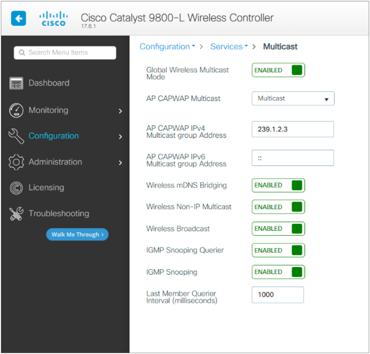
Follow the instructions below to configure Multicast mode.
In the Catalyst 9800 UI, navigate to Configuration > Services > Multicast.
Step 1. Set the AP CAPWAP Multicast mode to Multicast.
Step 2. Configure a multicast group address.
Step 3. Enable IGMP snooping.
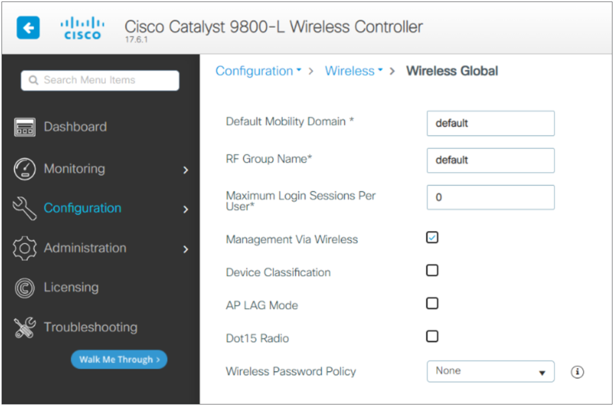
Step 4. Make sure the mobility domain and RF group name are the same across the entire wireless and mobility domain.
Step 5. Click Apply.
Wireless datapath
We recommend configuring a separate VLAN for the Vocera badges to separate their traffic from other voice and data traffic. Configure a native VLAN for access point management traffic, a data VLAN for data traffic, a voice or auxiliary VLAN for voice traffic, and a VLAN for the Vocera badges.
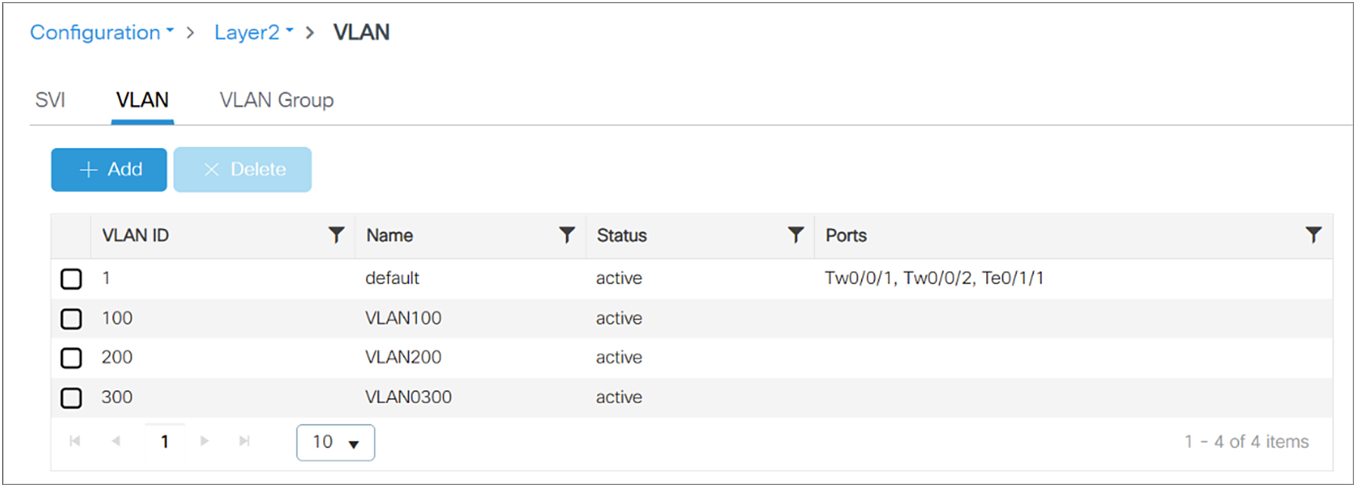
In the Catalyst 9800 UI, navigate to > Configuration > Layer 2 > VLAN.
Step 1. Choose the VLAN tab.
Step 2. Add a VLAN that can be used for Vocera badges and clients connecting to the network.
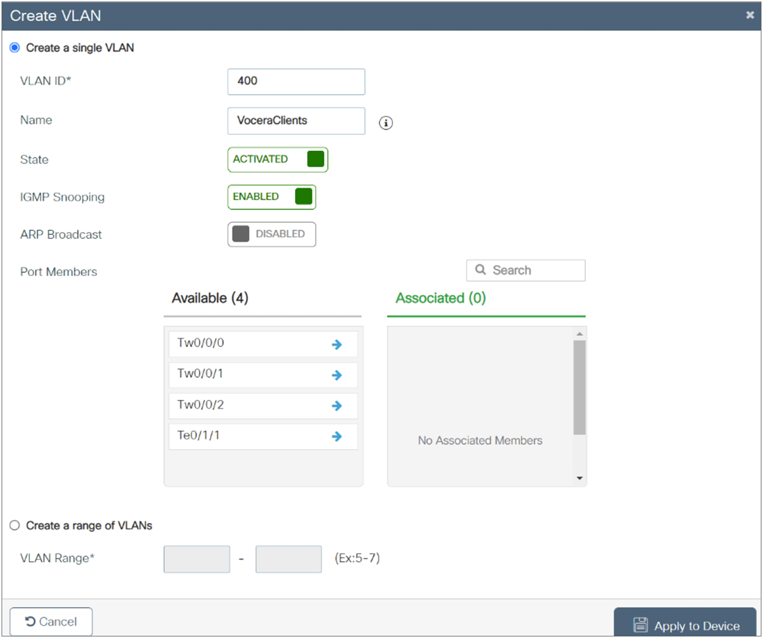
Note: Make sure to configure this VLAN, which is planned for use by Vocera badges, in the policy profile mapped to the WLAN profile.
Multicast Optimization
Multicast optimization enables you to create a multicast VLAN that can be used for multicast traffic. One of the VLANs in the device can be configured as a multicast VLAN where multicast groups are registered. The clients are allowed to listen to a multicast stream on the multicast VLAN. The MGID is generated using the multicast VLAN and multicast IP addresses. If multiple clients on different VLANs of the same WLAN are listening to a single multicast IP address, a single MGID is generated. The device makes sure that all the multicast streams from the clients on this VLAN group always go out on the multicast VLAN to ensure that the upstream router has one entry for all the VLANs of the VLAN group. Only one multicast stream hits the VLAN group even if the clients are on different VLANs. Therefore, the multicast packets that are sent out over the network is just one stream.
Note: When VLAN groups are defined and uses multicast communication, then you need to enable the multicast VLAN.
Refer the wireless multicast section in the configuration guide: https://www.cisco.com/c/en/us/td/docs/wireless/controller/9800/17-8/config-guide/b_wl_17_8_cg/m-vewlc-multicast-cg.html
Wireless LAN and security
For wireless LAN creation in the Cisco Catalyst 9800 Series, follow the instructions below and choose the required security configurations for the Vocera badges.
WLAN Creation
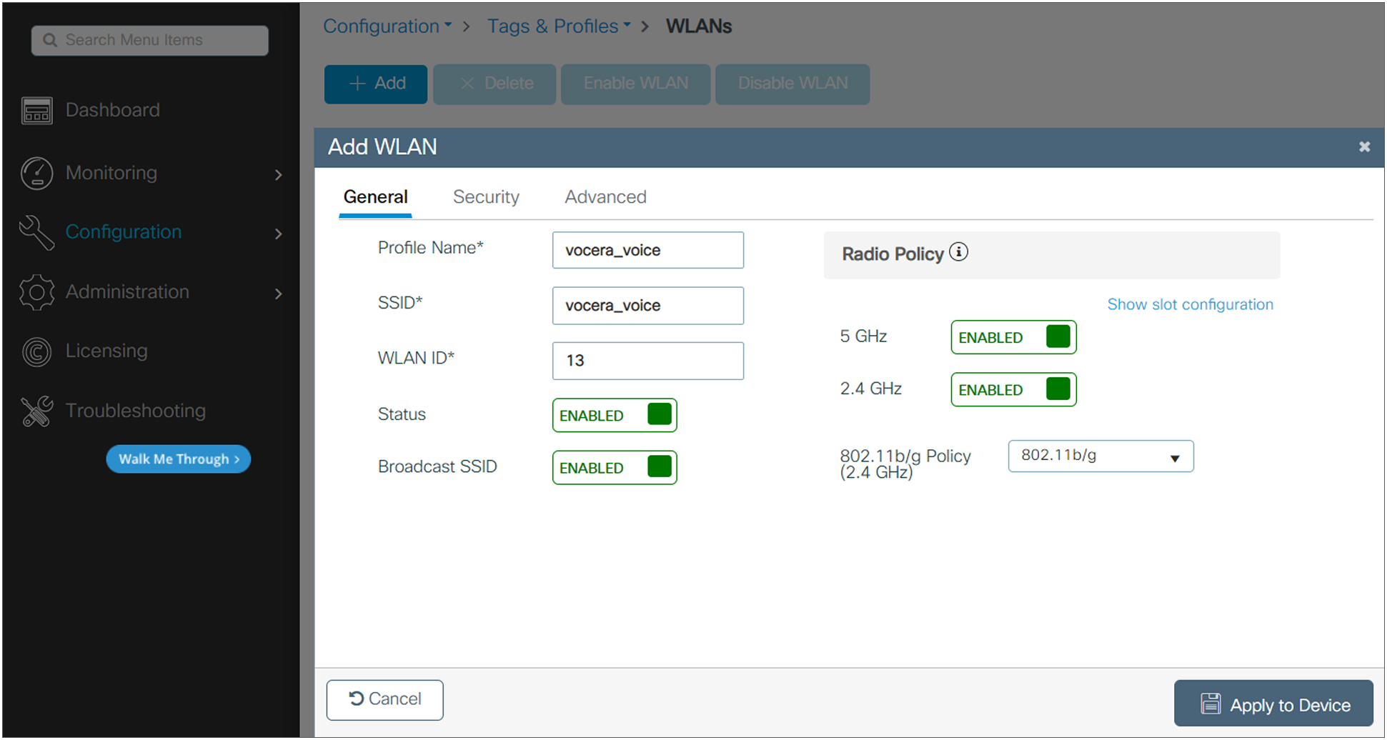
Step 1. In the Catalyst 9800 UI, navigate to Configuration > Tags & Profiles > WLANs and click Add to create a WLAN.
The Add WLAN window is displayed.
Step 2. Under the General tab, in the Profile Name field, enter the name of the WLAN. The name can be ASCII characters from 32 to 126, without leading and trailing spaces.
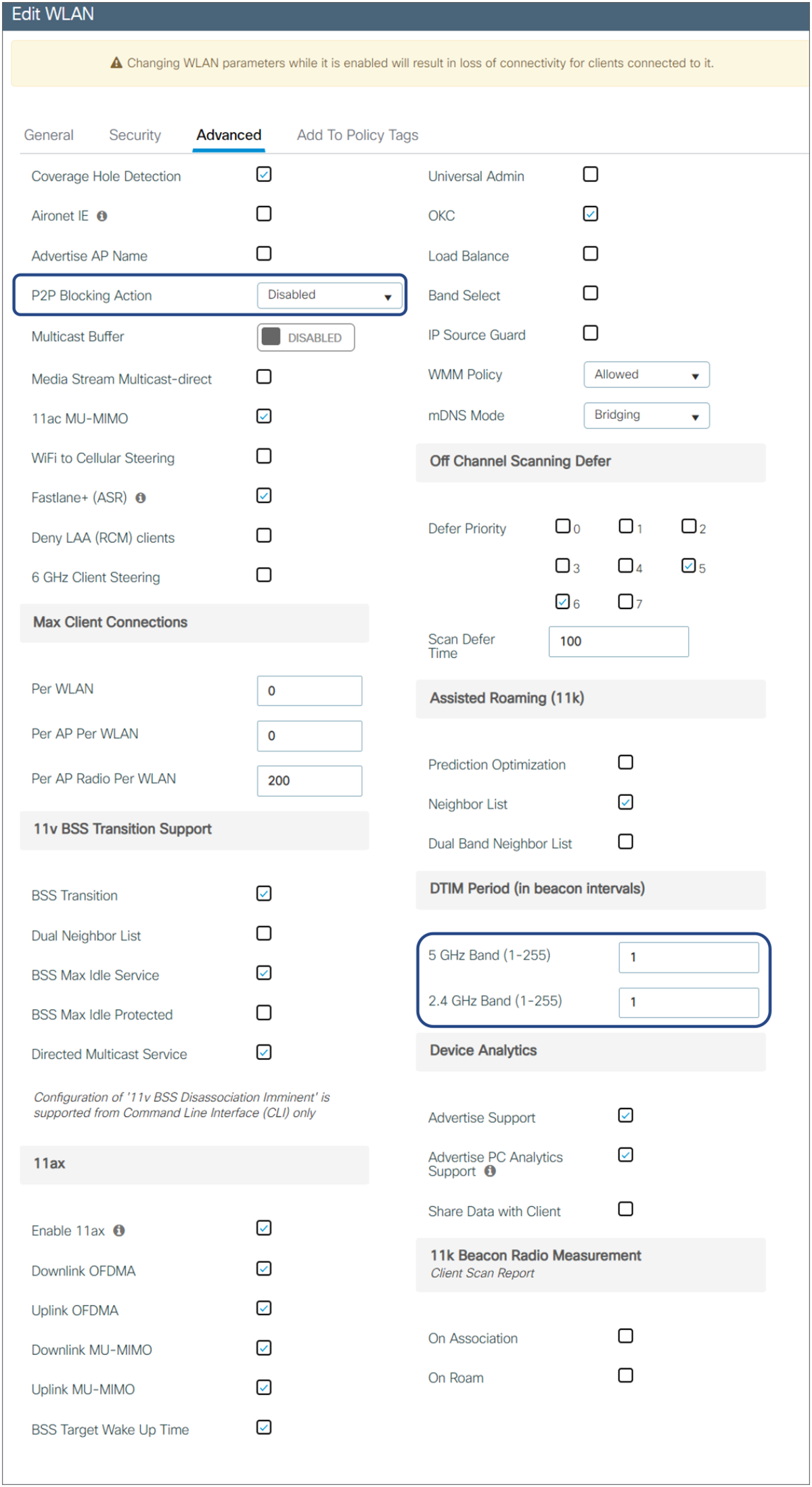
Step 3. Let the DTIM period in the WLAN be the default 1 for both the bands, and choose Disabled for P2P Blocking Action.
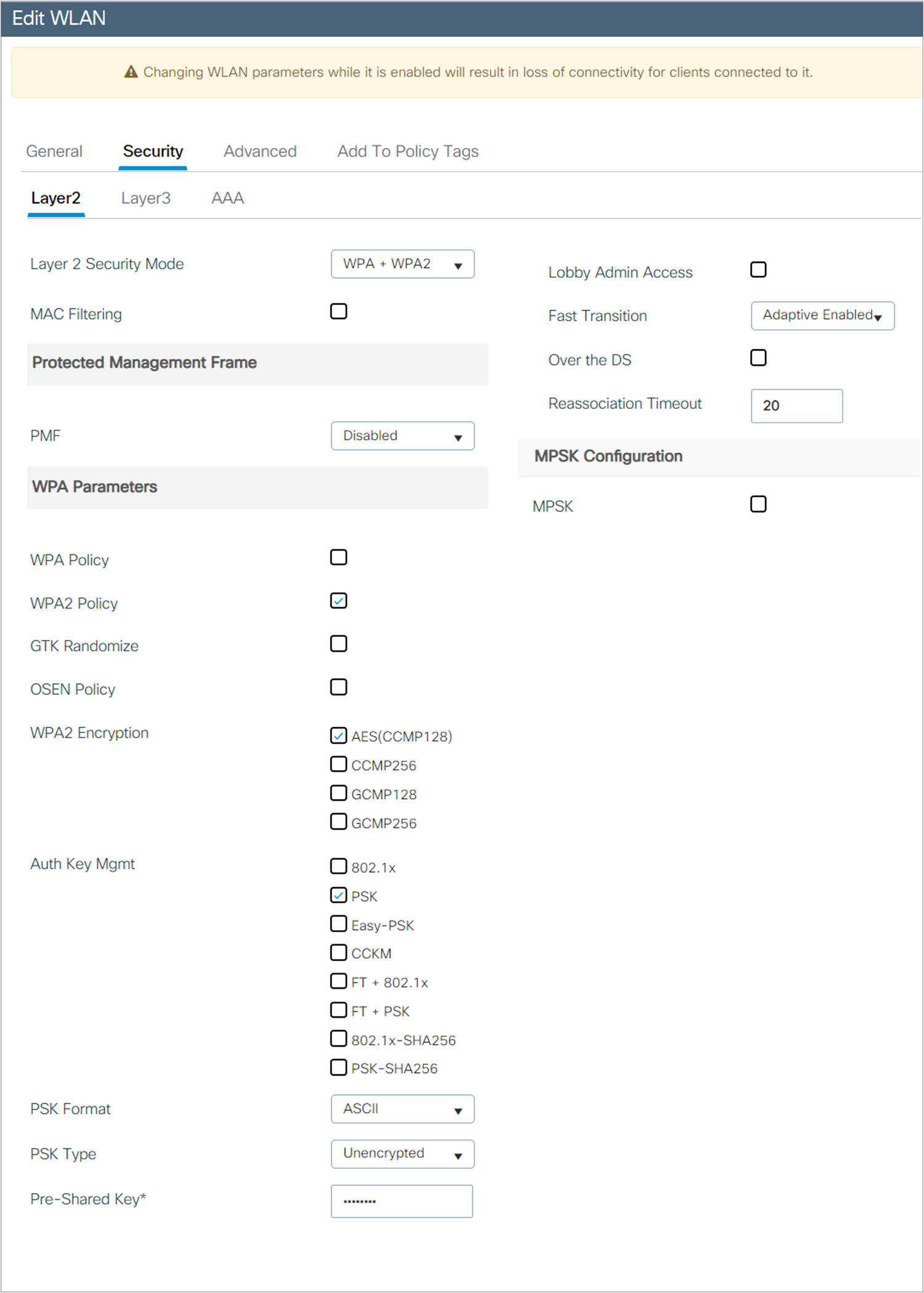
Step 4. Configure the Security method for this WLAN as follows.
Vocera supports industry-standard security systems as well as popular proprietary security methods such as EAP-TLS and WPA/WPA2-PEAP.
The following table summarizes the security support in Vocera.
Table 6. Security methods for badge models
| Authentication |
Encryption |
B3000n support |
V5000 support |
| Open |
None |
✓ |
✓ |
| WPA-PEAP WPA-PSK EAP-FAST EAP-TLS |
TKIP-WPA TKIP-WPA TKIP-WPA TKIP-WPA |
✓ |
✓ |
| WPA/WPA2-PEAP WPA/WPA2-PSK EAP-FAST EAP-TLS CCKM |
AES-CCMP AES-CCMP AES-CCMP AES-CCMP |
✓ |
✓ |
| LEAP |
WEP64 WEP128 TKIP-WPA AES-CCMP |
✓ |
✓ |
| FT-PSK FT-EAP |
AES-CCMP |
✓ |
✓ |
Step 5. Click Save & Apply to Device.
For more information on WLAN configuration, refer to the Cisco Catalyst 9800 Series Wireless Controller Software Configuration Guide at https://www.cisco.com/c/en/us/td/docs/wireless/controller/9800/17-3/config-guide/b_wl_17_3_cg/m_wlan_9800.html
Encryption and authentication
Vocera devices support WPA2 (AES-CCMP encryption), with PEAP (MS-CHAP v2), LEAP, EAP-TLS, EAP-FAST, and PSK authentication.
WPA2, a pre-shared key, is a secure and strong encryption protocol. It is a stronger algorithm for message integrity and confidentiality. It uses AES (Advanced Encryption Standard) in conjunction with counter mode with Cipher Block Chaining Message Authentication Code Protocol (CCMP.)
These protocols require back-end authentication servers to authenticate client credentials the first time a client connects to the network, each time the client roams, and at periodic intervals. Various properties control how often the authentication occurs and, in the case of WPA-PEAP and EAP-FAST, whether a full authentication or a fast authentication occurs.
The authentication that occurs the first time a client connects to the network is not noticeable to a badge user because it appears to be part of the general boot and connection procedure. However, the authentication that occurs during roaming or at a timeout interval can interrupt a conversation. This happens because packets are lost while the authentication server processes credentials and reauthenticates the badge. You can optimize badge performance by allowing fast reconnects and setting a lengthy timeout interval.
Assisted roaming: 802.11k
The 802.11k standards help in distributing traffic within a network. They provide radio resource measurements designed to allow a wireless client to request details of the neighboring access points.
Having a list of neighboring access points avoids active and passive scanning, and the device makes more informed roaming decisions by discovering the best available access point.
For example, the 802.11k neighbor report provides measurements and information about nearby potential roaming points to the wireless client. An 802.11k client device can also determine whether an end-to-end link can carry a voice call reliably.
Note: To enable it, refer the following C9800 WLC configuration guide: https://www.cisco.com/c/en/us/td/docs/wireless/controller/9800/config-guide/b_wl_16_10_cg/assisted-roaming.html
Fast Transition Roaming: 802.11r
The 802.11r standard is designed to permit continuous connectivity for devices in motion. 802.11r addresses Fast Roaming and BSS Fast Transitions.
The key consideration is the roaming delay penalty imposed by the lengthy handshake between the supplicant, authenticator, and authentication server in WPA or WPA2-Enterprise mode. 802.11r minimizes the loss of connectivity to the wireless distribution system during such BSS transitions, thus preventing degradation of voice quality.
To take advantage of 802.11r, your access points and B3000n badges must be configured to enable 802.11r. You can use a WPA2 pre-shared key passphrase, EAP-FAST, EAP-PEAP, or EAP-TLS authentication. For more information on how to configure badges for 802.11r, refer to the Vocera Badge User Guide.
Refer the following C9800 WLC configuration guide to enable the fast transition roaming: https://www.cisco.com/c/en/us/td/docs/wireless/controller/9800/config-guide/b_wl_16_10_cg/802-11r-bss-fast-transition.html
Vocera device support standards
The following table maps the IEEE standards for frequency bands to Vocera firmware, software, and supported devices.
Table 7. Supported IEEE standards in Vocera software and devices
| IEEE standard |
Frequency bands |
Vocera software |
Devices |
| 802.11a/n |
5.0 GHz |
Vocera Voice Server 4.3, Vocera Server 4.4 and later |
B3000n, iOS, and Android |
| 802.11b/g |
2.4 GHz |
Vocera Voice Server 4.1 and later |
B3000, B3000n, iOS, and Android |
| 802.11k/r/w |
2.4 and 5.0 GHz |
Vocera Voice Server 5.2.0 and later |
B3000n and V5000 |
Note: The V5000 does not support FT over DS.
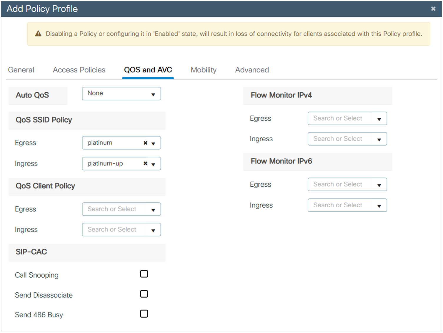
Policy profile
For a WLAN that has only Vocera badges, use the following configuration sample settings that best support the Vocera badges’ quality of service and session contracts:
Policy profile: Contains policy to be associated with the WLAN. It specifies the settings for client VLAN, quality of service, and so on.
Step 1. Step 1: To create a policy profile for the Vocera Badge service in the Cisco Catalyst 9800 Series, navigate through the UI to Configurations > Tags & Profiles > Profiles.
Step 2. Step 2: Configure a Platinum QoS SSID policy in both the upstream and downstream directions.
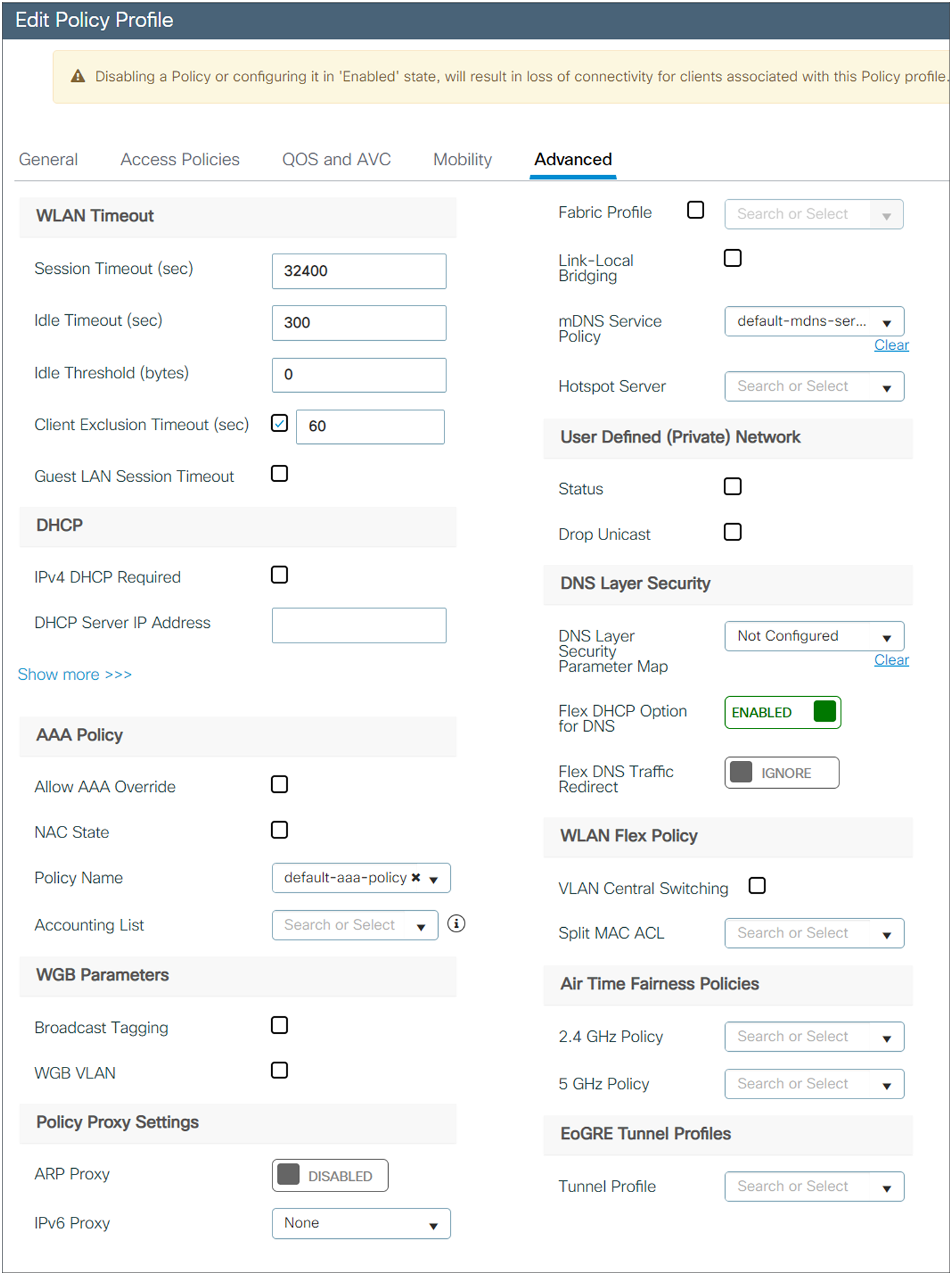
Step 3. Configure a WLAN session timeout that best suits a shift timing.
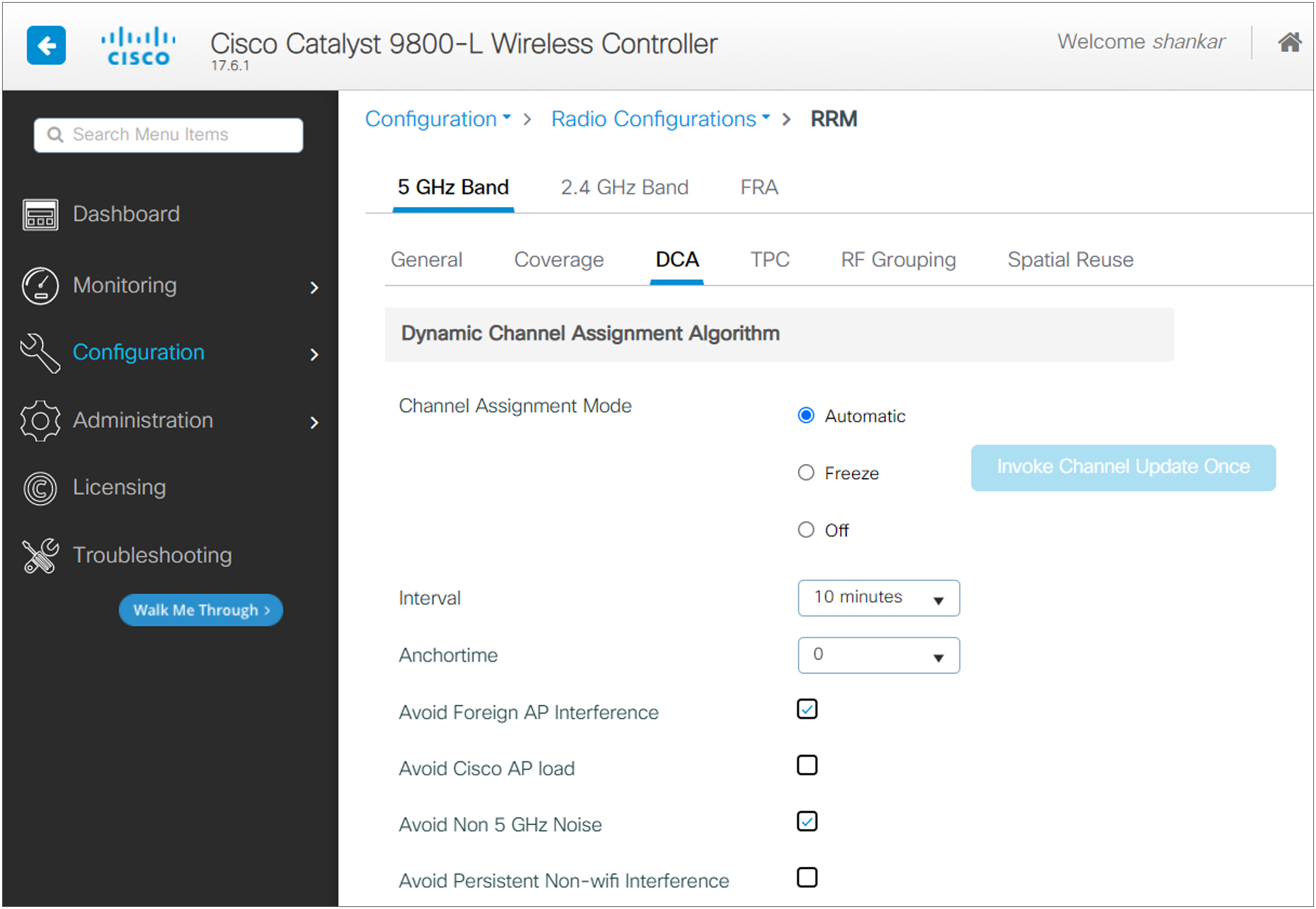
Radio resource management
RRM is a great tool, and features like Dynamic Channel Assignment (DCA) and Transmit Power Control (TPC) can automatically set the best channel and power plan, but remember: RRM cannot correct a bad RF design. The site survey must be done with devices that match the power and propagation behavior of the devices to be used on the real network.
Use AutoRF to create complete coverage with nonoverlapping RF channels and a transmit power. To do this, select Automatic for both RF Channel Assignment and Tx Power Level Assignment.
Make sure to configure AutoRF in both the 2.4-GHz and 5-GHz bands. Set the Anchortime to 0 and the DCA Interval to match one shift time (8 or 12 hours).
Access point configurations
The tag allows you to bind the settings in the profiles to an access point. There are three types of tags:
● Policy tag: Ties together the policy profile and the WLAN.
● Site tag: Assigns the AP Join profile settings to the access point and determines whether the site is a local site, in which case the access points will be in local mode, or is not a local site, in which case the access points will be in Cisco FlexConnect mode.
● RF tag: Binds the 5-GHz and 2.4-GHz profiles to the access point.
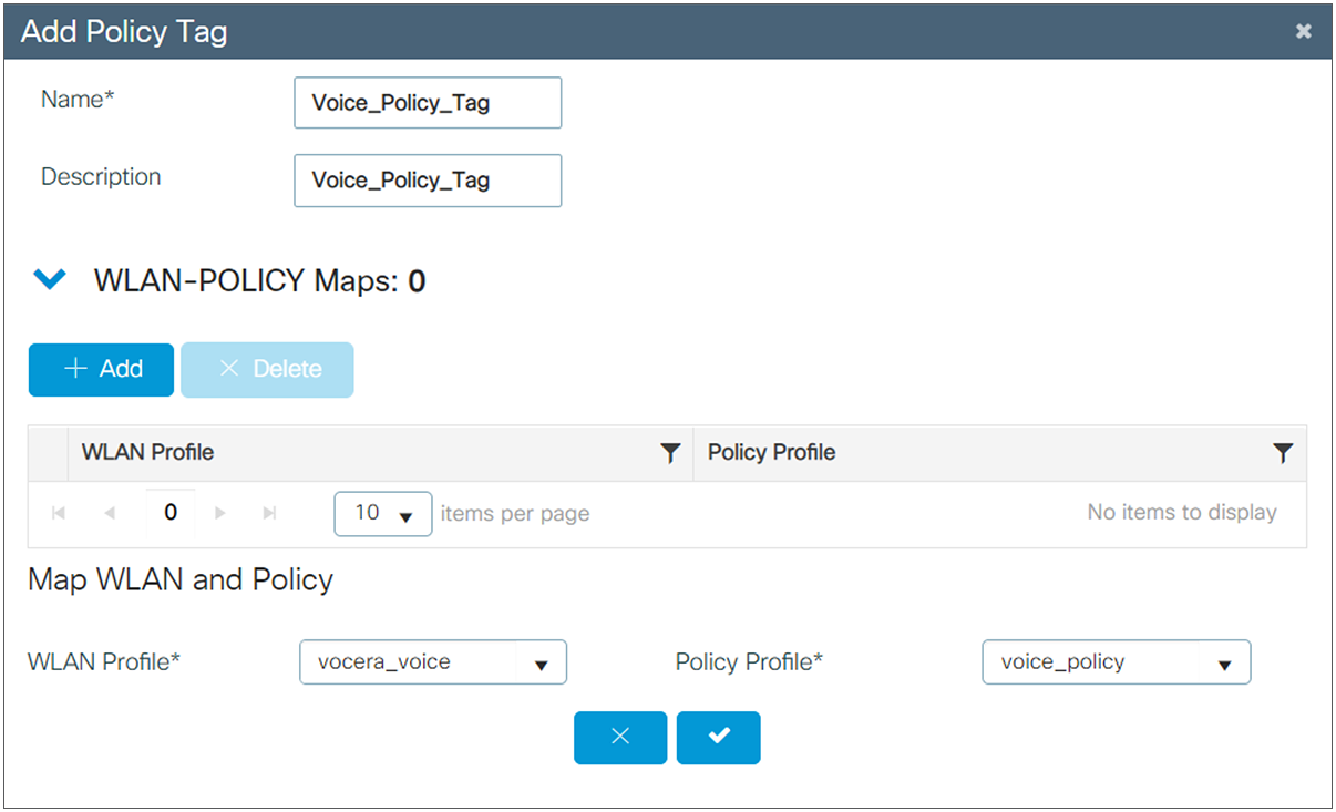
Create a Policy tag
The Policy tag is the setting that allows you to map the WLAN profile to the policy profile.
Step 1. Navigate to Configuration > Tags & Profiles > Tags > Policy. Either select the name of a pre-existing policy or click +Add to add a new one.
Step 2. Inside the Policy tag, click +Add, and from the drop-down list select the WLAN profile name you want to add to the Policy tag and the policy profile to which you want to link it. After that, click the check mark.
Policy tag mapping
You can assign a Policy tag directly to an access point or assign the same Policy tag to a group of access points at the same time. Choose the one that fits your situation.
Policy tag assignation per access point
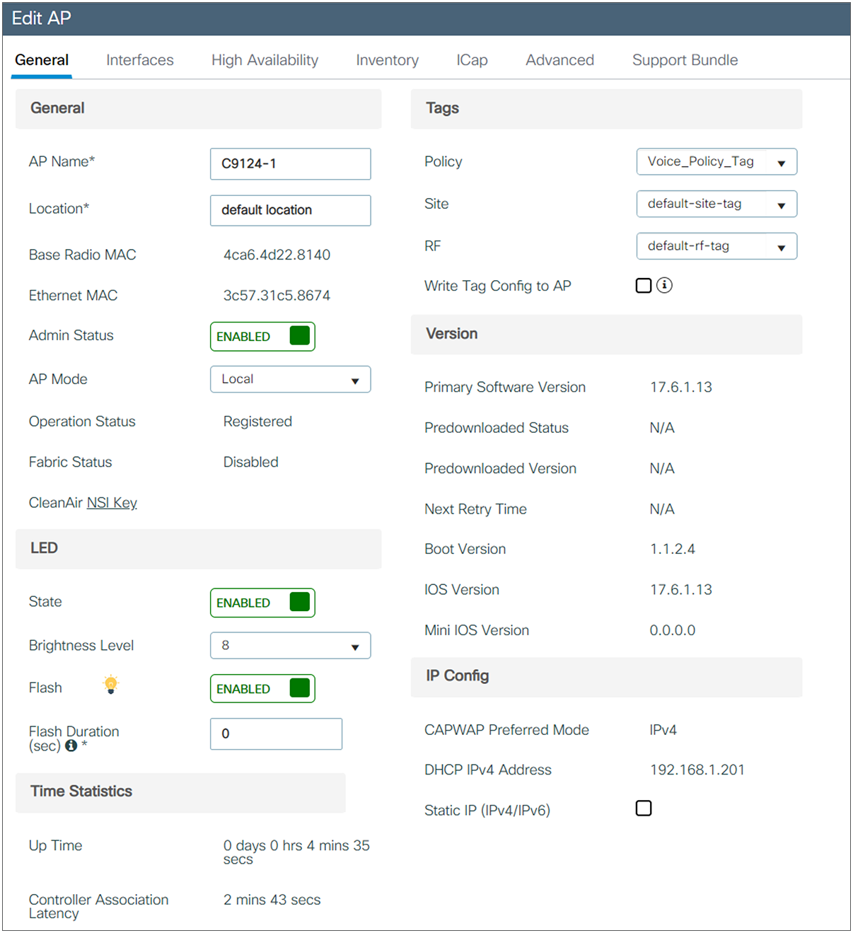
Navigate to Configuration > Wireless > Access Points > AP name > General > Tags. From the Policy drop-down list, select the desired Policy tag and click Update & Apply to Device.
Note: Be aware that after you change the Policy tag on an access point, it loses its association to the 9800 WLCs and joins back within about 1 minute.
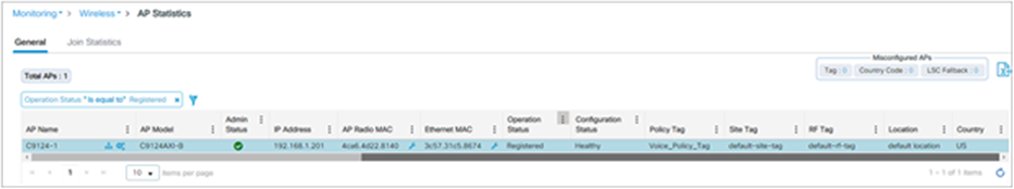
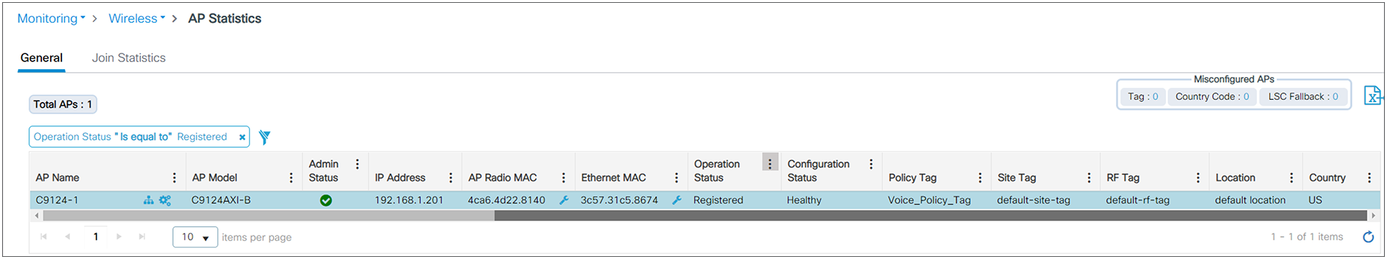
Check that the access point boots up with the correct configuration and that the Configuration Status stays “Healthy.”
For more information on AP tag assignment based on location or filter, refer the document: https://www.cisco.com/c/en/us/td/docs/wireless/controller/9800/config-guide/b_wl_16_10_cg/new-configuration-model.html#task_k2c_nps_xfb
Reliable multicast
The IEEE 802.11 wireless multicast delivery mechanism does not provide a reliable way to acknowledge lost or corrupted packets. As a result, if any multicast packet is lost in the air, it is not sent again, which may cause an IP multicast stream to be unviewable.
The MediaStream feature makes the delivery of the IP multicast stream reliable over the air by converting the multicast frame to a unicast frame over the air. Each MediaStream client acknowledges receiving a video IP multicast stream. Refer to Configure VideoStream on Catalyst 9800 WLC for more information and configurations. https://www.cisco.com/c/en/us/support/docs/wireless/catalyst-9800-series-wireless-controllers/215859-video-stream-on-catalyst-9800-wireless-c.html
Switch recommendations (supporting WLC configuration)
Multicast routing
IP multicast routing allows Cisco IOS Software to forward multicast packets. The IP multicast-routing global configuration command is required to allow multicast to function in any multicast-enabled network. The “ip multicast-routing” command should be enabled on all routers within your network between the WLC(s) and their respective access points.
Enable PIM on the interface
Enabling PIM enables the routing interface for IGMP operation. The PIM mode determines how the router populates its multicast routing table.
IGMP snooping
IGMP snooping allows a switched network with multicast enabled to limit traffic to those switch ports that have users who want to see the multicast stream while pruning the multicast packets from switch ports that do not wish to see the multicast stream.
When Wi-Fi Multimedia (WMM) properties are enabled in the badge, the badge takes advantage of the WMM subset of 802.11e. The 802.11e QoS prioritizes voice traffic over data traffic to help ensure high-quality voice transmission.
To take advantage of this standard, the Cisco access points and WLC must also have the supporting configurations. In addition, the underlying switches and routers must be configured to honor Differentiated Services Code Point (DSCP) markings, and the Vocera QoS Manager service must be enabled on the Vocera Voice Server.
VLANs provide a mechanism for segmenting networks into one or more broadcast domains. VLANs are especially important for IP telephony networks, where the typical recommendation is to separate voice and data traffic into different Layer 2 domains. Cisco recommends that you configure separate VLANs as follows: a native VLAN for access point management traffic, a data VLAN for data traffic, a voice or auxiliary VLAN for voice traffic, and a VLAN for the Vocera badges. A separate voice VLAN enables the network to take advantage of Layer 2 marking and provides priority queuing at the Layer 2 access switch port. This helps ensure that appropriate QoS is provided for various classes of traffic and helps to resolve addressing issues such as IP addressing, security, and network dimensioning. The Vocera badges use a broadcast feature that is delivered via multicast. This common VLAN ensures that when a badge roams between controllers, it remains part of the multicast group. Segregate other services learnt through SSDP or mDNS. Make sure to have a separate VLAN for Vocera badges and other services.
Enable PortFast to allow a switch to quickly resume forwarding traffic if a Spanning Tree link goes down.
Network/coverage recommendations
Cisco recommends the parameters listed in the table below as coverage requirements to deploy a Vocera and Cisco wireless network.
Table 8. Recommended coverage parameters
| Parameter |
Recommended value |
| Latency |
< 100 ms |
| Jitter |
< 100 ms |
| Packet loss |
< 1% |
| Minimum AP coverage |
-65 dBm |
| Minimum SNR |
25 dB |
| Radio channel utilization |
< 50% |
| Coverage overlapping |
20% |
Badge configuration recommendations
Table 9. Recommended badge parameters
| Parameter |
Value |
| Voice-grade site survey |
Required |
| Badge transmit power |
Max: 16 dbm (40mW) Min: 13dBm (20mW) |
| Minimum power coverage |
-65 dBm |
| Minimum SNR |
25 dB |
| Noise floor |
-90 dB |
| Beacon interval |
100 ms |
| DTIM interval |
1 |
| Priority queue |
Voice |
| Radio channel utilization |
Not more than 50% |
| Channel width |
2.4 GHz: 20 MHz 5 GHz: 40 MHz |
| Channel plan |
2.4 GHz: 1, 6, 11 5 GHz: 36, 40, 44, 48, 149, 153, 157, 161 |
| Roaming policy |
2 |
| Maximum number of SSIDs |
5 |
| Client exclusion |
Disabled |
| Authentication timeouts |
1 shift duration + 1 hour |
| DHCP |
Enabled |
| 5-GHz channels |
Must match 5-GHz channels enabled in the controller |
| IGMP |
Enabled |
| IGMP v2 on the network |
Enabled |
| Multicast configuration |
See section |
| Configure WLAN to use 802.11a band |
Recommended |
| Set user idle time to session timeout definition |
Required |
WLC configuration recommendations
Table 10. Recommended WLC parameters
| Parameter |
Value |
| RRM DCA |
Automatic with one shift duration timer |
| RRM TPC |
Automatic with one shift duration timer |
| Transmit power threshold |
Adjust to fit site |
| Coverage hole |
Disabled: If coverage hole detection is necessary, enable it with the following settings:
● Set Voice RSSI (-60 to -90 dBm) to -70
● Set Min Failed Client Count per AP to 12
|
| Multicast mode |
Multicast, direct |
| Multicast data rate |
Highest data rate. 12 Mbps and 24 Mbps as mandatory data rates. |
| IGMP snooping |
Enabled |
| IGMP snooping querier |
Enabled |
| WMM |
Enabled |
| U-APSD |
Enabled |
| Priority queue |
Voice (Platinum) |
| Band select |
Disabled |
| Client load balancing |
Disabled |
| Unicast ARP |
Disabled |
| ARP proxy |
Enabled |
| DHCP address assignment |
Disabled |
| WLAN P2P blocking action |
Disabled |
| Broadcast forwarding |
Enabled |
| Multicast forwarding |
Enabled |
| Admission control |
Disabled |
| WLAN QoS policy |
Set it to Platinum |
| FRA |
Disabled |
| Interface Group |
Not recommended |
Table 11. Other recommended settings
| Parameter |
Value |
| Infra type |
Controller based |
| Security |
WPA2 |
| Encryption |
AES |
| Authentication |
PSK (Enable PSK and FT-PSK) |
| Operational data rates |
2.4 GHz: 6, 9, 11, 12, 18, 24 5 GHz: Data rates change depending on the site |
| Fast roam methods |
OKC, FT |
| DTIM interval |
1 |
| Beacon |
100 |
| Bandwidth |
20 MHz |
| WMM |
Enabled |
| 802.11k |
Enabled |
| 802.11w |
Enabled |
| 80211v |
Enabled |
Network validation and troubleshooting
After you conduct an RF site survey and configure the access points and the badges, it is crucial to conduct verification tests to ensure that everything works as desired. These tests should be performed at all these locations:
● The primary area of each access point cell (where the badges are more likely to connect to that access point)
● Any location where there might be high call volumes
● Locations where usage might be infrequent, but coverage still has to be certified (for example, stairwells, restrooms, and so forth)
● At the fringes of the access point’s coverage area
These tests can be performed in parallel or as a series. If performed in parallel, ensure that badges are powered off between testing points to test full association, authentication, and registration at each location. Roaming and load tests must be the final tests.
Registration and traffic verification
This section explains how to verify that the badges associate, authenticate, and register properly.
● At multiple points throughout the environment, power up the badges and verify association with the access point. If a badge does not associate with the access point, perform these checks:
◦ Check the badge configuration to ensure proper SSID, authentication type, and so forth.
◦ Check the WLC configuration to ensure proper SSID, authentication type, radio channels, and so forth.
◦ Check your site survey to ensure that the location has adequate RF coverage.
● At multiple points throughout the environment, ensure that the badges authenticate through the access point successfully. If the client does not authenticate, check the security parameters/username and password on the badges. Also check the username and password on the Authentication, Authorization, and Accounting (AAA) server by using a wireless laptop with identical credentials.
● At multiple points throughout the environment, ensure that the badges register with the Vocera Communication Server. If the client does not register, perform these checks:
◦ Verify that the badge has the correct IP address, subnet mask, primary gateway, primary TFTP, and primary/secondary DNS.
● Stationary voice calls:
◦ At multiple points throughout the environment, while you stand still, make a call to another badge, and conduct 60- to 120-second voice tests to check voice quality. If the voice quality is unacceptable, move one badge to a better location and test again. Is the voice quality acceptable? If not, check your wireless coverage.
◦ If the telephony server is configured, at multiple points throughout the environment, stand still and make a call to a wired phone and conduct 60- to 120-second voice tests to check voice quality. If the voice quality is unacceptable, try making a call using a wired phone. Is the voice quality acceptable? If not, verify the wired network design against the guidelines.
● Use the site survey tools to verify that there is no more than one access point per RF channel from that location with a signal strength (received signal strength indicator [RSSI]) greater than 35. If there are two access points present on the same channel, ensure that the signal-to-noise ratio (SNR) is as high as possible to minimize interference. For instance, if the stronger access point has an RSSI of 35, ideally the weaker access point should have an RSSI of less than 20. To achieve this goal, you might have to reduce one access point's transmit power or move the access point.
● Check the QoS settings on the access point to confirm the proper recommended settings.
● Roaming badge calls:
◦ If the telephony server is not available, initiate the Vocera Tutorial with the command Begin Tutorial.
◦ If the telephony server is available, initiate a call with a stationary device to the badge.
◦ Continually check voice quality while you traverse the total wireless coverage area. If the voice quality is insufficient, perform these tasks:
◦ Listen for all unacceptable changes in voice quality and take note of the location and radio values on your laptop and Channel Quality (CQ) values from the badge.
◦ Watch and listen for the badge to roam to the next access point.
◦ Note the other available access points in the site survey to check coverage and interference.
● Adjust access point placement and settings to fine-tune the WLAN, and perform these checks to ensure voice quality:
◦ Use the site survey tools and verify that there is no more than one access point per channel with an RSSI value greater than 35 in any given location. Ideally, all other access points on the same channel should have RSSI values as low as possible (preferably less than 20). At the border of the coverage area, where the RSSI is 35, the RSSI for all other access points on the same channel should ideally be less than 20.
◦ Use the site survey tools to verify that at least two access points (total, on separate channels) are visible in all locations with sufficient signal strength.
◦ Check that the access points in a given roaming area are all on a Layer 2 network.
The following roaming issues can occur:
● The badge does not roam when placed directly under the access point.
● The badge is most likely not reaching the roaming differential thresholds for the RSSI and Channel Utilization (CU). Adjust the Transmit Power Threshold in the WLC.
● The badge does not receive beacons or probe responses from the access point. In case of such issues, check the operation status and radio status of AP and possible OTA packet traces can be used to troubleshoot or triage the issue.
● The badge roams too slowly.
● Voice Quality Deteriorates While Roaming
◦ Check the RSSI on the destination access point to see if the signal strength is adequate. The next access point should have an RSSI value of -67 dBm or greater.
◦ Check the site survey to determine if the channel overlap is adequate for the device and the access point to hand off the call to the next access point before the signal is lost from the previous access point.
◦ Check to see if noise or interference in the coverage area is too great.
◦ Check that signal to noise ratio (SNR) levels are 25 dB or higher for acceptable voice quality.
Following documents are available for references and as a quick guide to troubleshoot various wireless issues, https://www.cisco.com/c/en/us/support/docs/wireless/catalyst-9800-series-wireless-controllers/213949-wireless-debugging-and-log-collection-on.html