Introduction
The C9800 Product line is designed as a direct replacement for Current Hardware Wireless Lan Controller platforms. C9800 is compatible with AireOS based systems and follows the well established IRCM model (Inter Controller Release Matrix). For version 16.10, you will require AireOS version 8.8 MR1 or above. The workflow will follow – Configure Global RRM configuration, Global Data Rate configuration, Global HT/VHT.
Greenfield C9800 RRM Design and Configuration Considerations
Greenfield C9800 RRM Design and Configuration Considerations
The first thing to consider is the RF Group Name. The RF Group name is not the same as the Mobility Group name although it may be populated the same from day 0 startup scripts. The RF Group name is the administrative name assigned to all wireless within your network and is used extensively to identify the devices to one another that comprise your network. It is used in controller grouping as well as OTA neighbor messaging between AP’s. Two AP’s that do not share the same RF Group will not create a neighbor relationship and will treat each other as rogue devices. For more information on RRM grouping functions – please see Radio Resource Management White Paper.
To set or change the RF Group Name on the c9800:
-
Select Administration from the main menu
-
Select Devices/Wireless
-
Edit or create the RF Group Name
-
Select Apply to Device
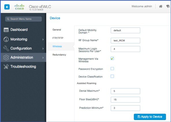
After creating the RF Group name, configuration progresses much the same as with existing AireOS controllers and should be familiar to most readers.
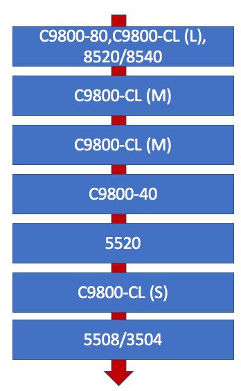
RF Grouping Maximum AP capacity’s differ by controller Model/Capacity. Grouping one or more Controllers of different capacity together will observe a hierarchy. The largest (most computationally capable) controller will be the RF group Leader. RRM is a centralized process – in which all members of the RF group report to the RF group leader. Hence RRM is aware of every ap, all of its neighbors, and how they relate to one another in RF distance.
Controller Hierarchy is ranked from the least to the most computational capable. . As an example, a 3504 cannot be the group leader for an 8540, the configuration will not allow it and the 8540 will assume the roll as soon as the two are grouped. There are two modes of RF Grouping – Auto and Static. The difference between the modes is explained well in the 8.3 Radio Resource Management White Paper
|
Group Leader WLC |
Maximum APs |
Maximum AP/RF Group |
|---|---|---|
|
3504 |
150 |
500 |
|
C9800-L |
250 |
500 |
|
5508 |
500 |
1000 |
|
C9800-CL (Small) |
1000 |
2000 |
|
5520 |
1500 |
3000 |
|
C9800-40 |
2000 |
4000 |
|
C9800-CL (Medium) |
3000 |
6000 |
|
8500/8540 |
6000 |
6000 |
|
C9800-CL (Large) |
6000 |
12000 |
|
C9800-80 |
6000 |
12000 |
The key thing to remember here with regards to the Maximum allowed number of AP’s in a group is that “Auto Mode” counts actual associated AP’s, “Static Mode” uses the licensed AP count of the controller – regardless of how many AP’s are actually associated.
Configure Global RRM configurations and Settings
General Tab
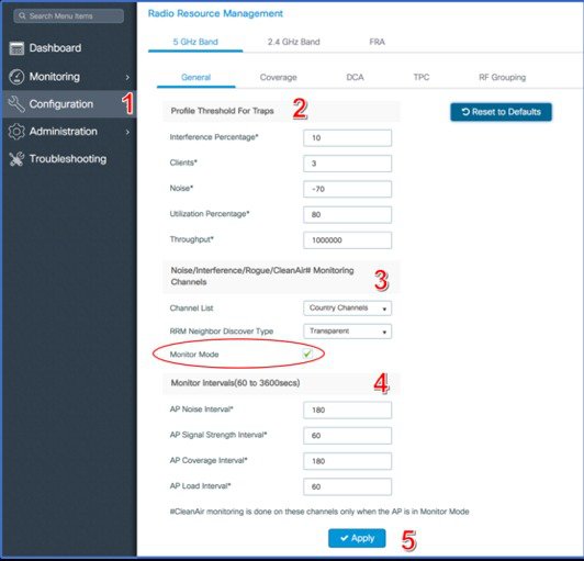
Select Configuration, RRM
-
Navigate to Configure – RRM – General tab.
-
Set appropriate trap thresholds for your environment, the defaults are fine.
-
Choose Monitor Channels and NDP encryption. Ignore Monitor Mode in this release, it will be removed in 16.11.
-
Adjust monitor intervals – (defaults are sufficient, and reflect pre AireOS 8.0 configurations, this will also be addressed in 16.11).
-
Click Apply.
-
Repeat these Steps for 2.4 GHz band.
Coverage TAB
-
Enable/Disable Global Coverage Hole
Detection
-
May be applied per Wlan or through RF profile’s covered later.
-
-
Repeat Steps for 2.4 GHz band.
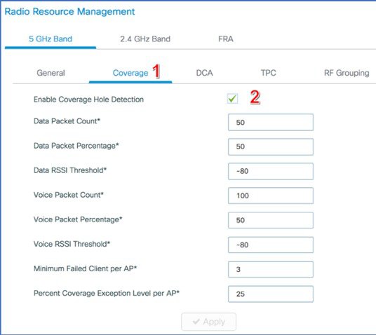
The default values are generally fine. Note: Data Packet and Voice Packet % have been added on the GUI, this is not exposed in AireOS model GUI (CLI only). These values allow fine tuning of the algorithm to a higher or lower percentage of packets meeting the criteria. Again, the default values are normally sufficient, these values can greatly increase or decrease the sensitivity, and should be changed only if directed or in a lab environment.
DCA Tab
-
Choose DCA operational mode (Automatic)
-
DCA Monitoring metrics
-
Choose Global Bandwidth
-
Select DCA operating channels
DCA Automatic applies the default 10 Minute run interval, this is recommended unless you are running realtime applications such as Voice or 2 real-time two way Video.. Cisco Best Practice for these environments is to use the Anchor Time option, and a 4 Hour interval. For a detailed description of DCA Anchor Time mode, please refer to 8.3 Radio Resource Management White Paper.
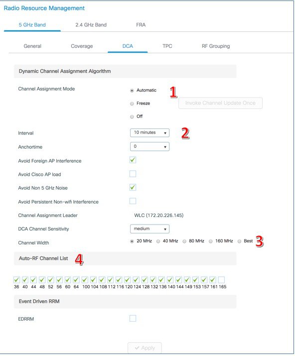
Channel Bandwidth selection if using best, should be limited to 40 MHz from the CLI interface in most environments, particularly where there is a high density of Dual 5 GHz AP’s operating (and especially if all are manually assigned dual 5 GHz role) as in this environment you will be using 8 channels per AP for 80 MHz channel assignments – in the US, there are 25 usable channels – and that makes a channel re-use ratio of 3/1. You will likely run out of channels if the AP’s are too close. Use the channel width width-max command below to set a maximum of 40 MHz.
C9800_1610(config)#ap dot11 5ghz rrm channel dca chan-width width-max 40
NOTE: Remember to hit Apply when changing any values
 Note |
Remember to hit Apply when changing any values. |
TPC Tab
In the C9800 line of controllers, there is no TPCv2. This Algorithm has been deprecated in favor of TPCv1 with Channel aware mode enabled. Channel Aware mode is not supported in version 16.10 of the code, but will be in 16.11.
-
Choose TPC operational mode (Automatic)
-
Min and Max power settings
-
Set the TPCv1 Threshold
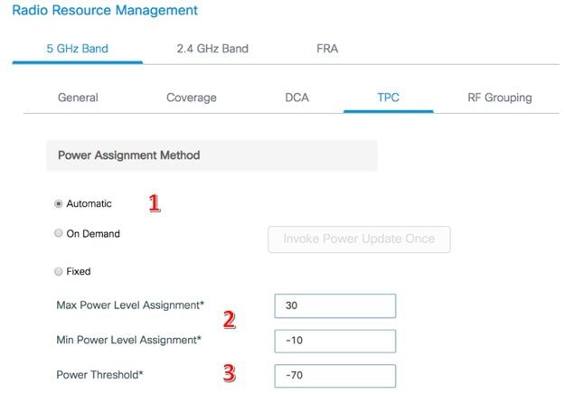
Min/Max Power Assignment Thresholds are a local configuration affecting only the AP’s associated to the local controller – not the entire RF Group. Assigned at the global configuration level – it will affect every AP associated to the controller. In order to apply a min/max threshold to a specific group of AP’s, or a group of AP’s that span multiple controllers within the RF group – assign this through use of an RF Profile which can be replicated on the other member controllers within the group.
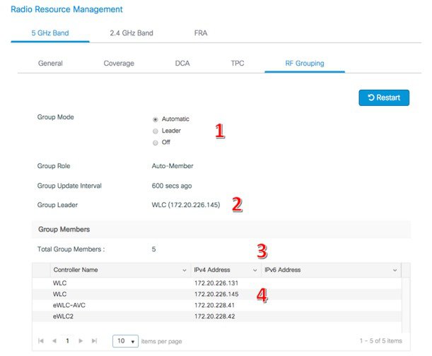
RF Grouping Tab
-
Choose RF Grouping operational mode (Automatic/Static Leader)
-
Identifies the current RF group leader for the displayed band
-
Identifies the individual member controllers forming the RF Group
-
Identifies RF Group Member WLC’s. Refer back to the RF Group AP Maximums located above (Table 1) for guidance on RF Group Members and RF Group Capacities.
Note |
Automatic mode counts AP’s by actual associated AP’s, and Leader (or Static Leader) counts the total uses the MAX AP count available for the selected c9800 platform regardless of the actual associated AP count. A C9800-CL will count as 1000 AP's towards the RF Group maximums in Leader mode. Refer to 8.3 Radio Resource Management White Paper for configuration steps and how to add member controllers to an RF Group Leader in the static Leader role. |
Note |
If Using FRA, both RF Group Leaders (5 GHz and 2.4 GHz) must reside on the same physical controller in order for FRA to function correctly. |
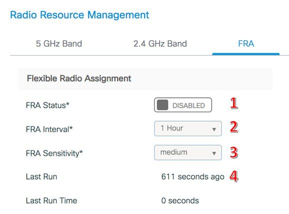
FRA Tab
-
Enable/Disable FRA
-
Choose Run Interval*
-
Choose Sensitivity level
-
Identifies time since last FRA cycle
Note |
Client Aware mode is not supported in 16.10 but will be in 16.11. |
*FRA interval must be set equal to or longer than DCA run interval. FRA runs and DCA runs immediately following to assign roles to FRA radios which are identified as redundant. See the RRM White paper – FRA chapter for a full description of FRA operation and configuration details.
If you inadvertently run FRA and start changing XOR radios before you are ready – resetting to legacy dual band (2.4/5 GHz) mode or placing all the XOR radios in FRA static mode to evaluate FRA results WITHOUT changing radio assignments can be done using the following CLI executable command.
C9800_1610#ap fra revert ?
all Revert all XOR radios
auto-only Revert only XOR radios currently in automatic band selection
C9800_1610#ap fra revert all ?
auto      Put XOR radios in automatic band selection
static    Put XOR radios in Static 2.4 G
To View FRA COF results in version 16.10 C9800 code, you will need to look at the CLI, use the sh ap fra command.
eWLC_1610_828#sh ap fra
FRA State                                             : Enabled
FRA Sensitivity                                       : high (90%)
FRA Interval                                          : 1 Hour(s)
  Last Run                                            : 2989 seconds ago
  Last Run time                                       : 0 seconds
Service Priority                                      : Coverage

AP Name          MAC Address       SlotID  Current-Band  COF %  Sensor % Suggested Mode
---------------------------------------------------------------------------------
3802i.DF.9C.20    58ac.78df.9c20    0      5GHz          92     none     5G/Monitor
AP4800.8B06.1560  7070.8b06.1560    0      5GHz          96     none     5G/Monitor
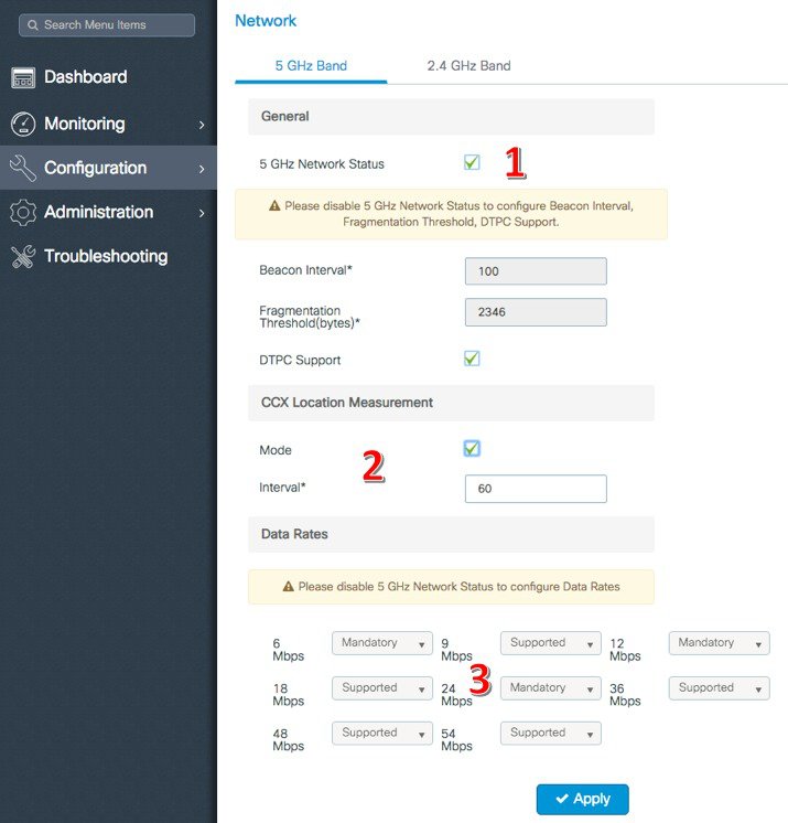
Network Configuration
Network level configurations such as enabling or disabling the RF network, or making changes to the data rate are part of RRM but play an important part in the RF domain. Network level configurations are local for each controller in the network and affect the AP’s associated to that physical controller.
-
Enable/Disable global Band
-
Choose CCX Location Measurement
-
Select Data-Rates and Role to be supported
Note |
It is not necessary to disable the band (2.4/5GHz) in order to change the data rates at the global level for the controller. |
 Caution |
Disabling either the 2.4 or 5 GHz network will disable RF on all APs associated to that controller for the entire band. |
High Throughput
Part of the configuration flow for data rates is the High Throughput data rates and protocols that will be supported on the network. This may seem to be an extension of the Network configuration, however it is different. Network configuration deals with legacy data rates which govern all management frames and beacons, strictly 802.11bga. High Throughput deals with HT and VHT data rates and control. Unless there is a very good reason, the defaults of all MCS’s enabled is preferred. However if you need to disable 802.11ac or 802.11n completely for any reason, this is where you will do that from.
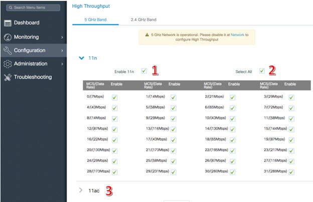
Select Configuration – High Throughput from the main menu
-
Enable/Disable 802.11n (HT) Support
-
Select all Data-rates (recommended best Practice)
-
Choose data-rates and states for 802.11ac (VHT) support
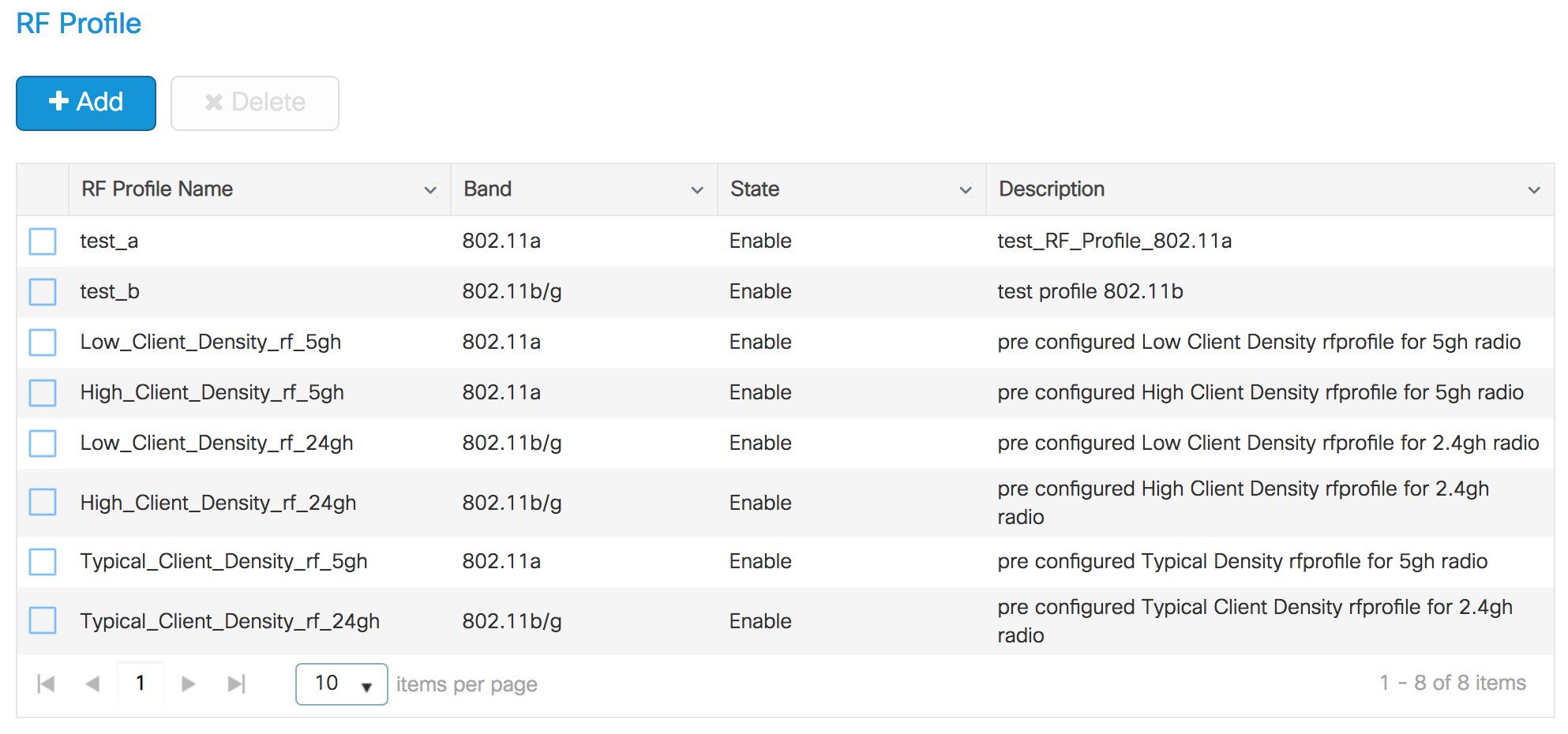
RRM and RF Profiles
RF Profiles in AireOS allowed selective override over a subset of AP’s RF and RRM parameters from the Global configuration level. When assigned to an AP group, the member AP’s of that AP group took on the RF Profile configurations and modified how RRM treated them. This remains the same in IOS XE and the C9800. In the C9800, RF Profiles are located under the Tags & Profiles configuration menu.
Select Configure, Tags and Profiles,RF (Profile)
Default Profiles are retained and displayed – select +Add to create new custom profiles.
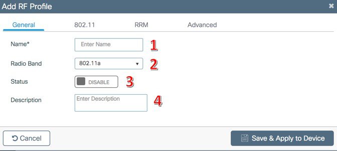
Creating a Custom RF Profile
RF Profiles are applied to a specific band of operation either 2.4 or 5 GHz, you can apply up to 2 per AP. Configuration options should be familiar to most readers familiar with AireOS options, differences will be noted.
Choose Addand you are presented with the Add RF Profile dialogue, general tab
-
Select Add-Choose a descriptive name
-
Choose the Band that the profile will apply too
-
Enable/Disable the profile
-
Write a description for later
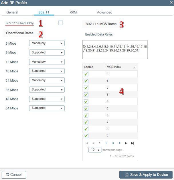
802.11 tab
-
802.11n Client Only.This should NOT be selected and will be removed from the GUI in version 16.11
-
Select Modified Data Rate support and role
-
Modify 802.11n MCS Data Rates, no support for 802.11ac data rates
-
HT and VHT Data Rates–Best Practice – all Enabled
Note |
Unlike AireOS you can change 802.11 parameters while the network is enabled even if the profile is applied to an RF Policy and AP’s exist. |
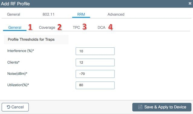
RRM Tab
The RF Tab contains the same selections retained from AireOS code, and should be very familiar to readers. RRM configuration Parameters within the RF Profile provide Overrides for Globally enabled settings. The hierarchy for the Global RRM process is RF Profile – RRM Global.
-
General–Trap Thresholds
-
Coverage – Coverage Hole Parameters
-
TPC–Min Max power and Threshold adjustments
-
DCA Channel set and Bandwidth modifications
Advanced Tab
The Advanced Tab provides access to other overrides to useful Global level configurations.
-
High Density Parameters
-
Client Load Balancing
-
*High Speed Roam
-
ATF Configuration Parameters
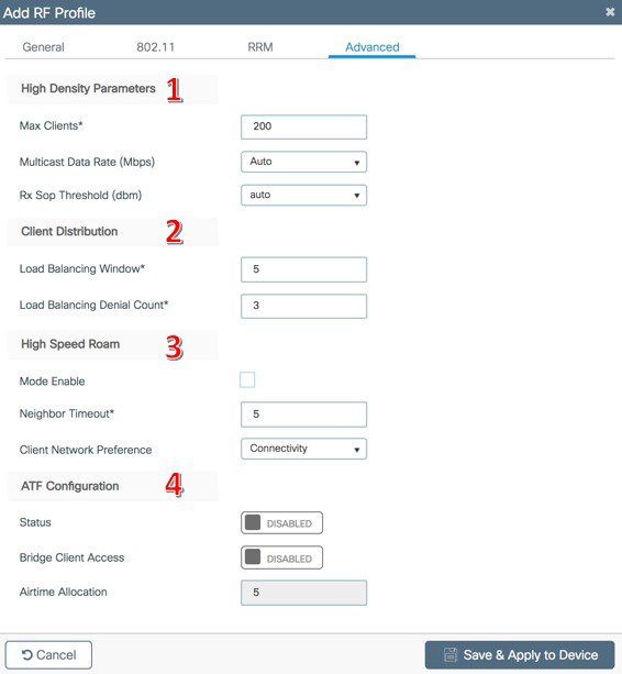
*High Speed Roam is a very specific feature only used on Transit systems like Subway Trains and similar – Not for roaming features associated with normal deployments.
C9800 Brownfield RRM/RF Group configuration considerations
Up until this point, we have focused on setting up an IOS XE controller in a pure IOS XE environment. However if you have AireOS 8.8 MR2 or above controllers that you are integrating with, RRM, FRA, and RF Profiles will all work, once you understand the mapping. IOS XE configuration follows a Policy and Profile Tagging model, and the concept of an AireOS AP group is not present on the surface.
An AireOS AP group consists of multiple configurations, which are all present within IOS XE, just laid out a bit differently. To RRM, the concept of an AP group is vital to retain as many of the RRM Algorithms limit their analysis to the AP’s contained within the AP Group. FRA for instance limits it’s coverage overlap calculation to only the AP’s contained within an AP group by design. AP Groups concept is a distributed function, all RF Profiles and AP Group constructs must reside on all controllers that contain member AP’s to any one of the above.
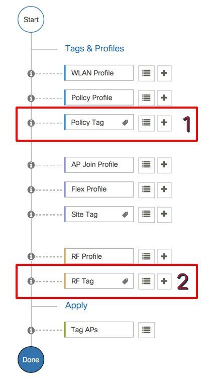
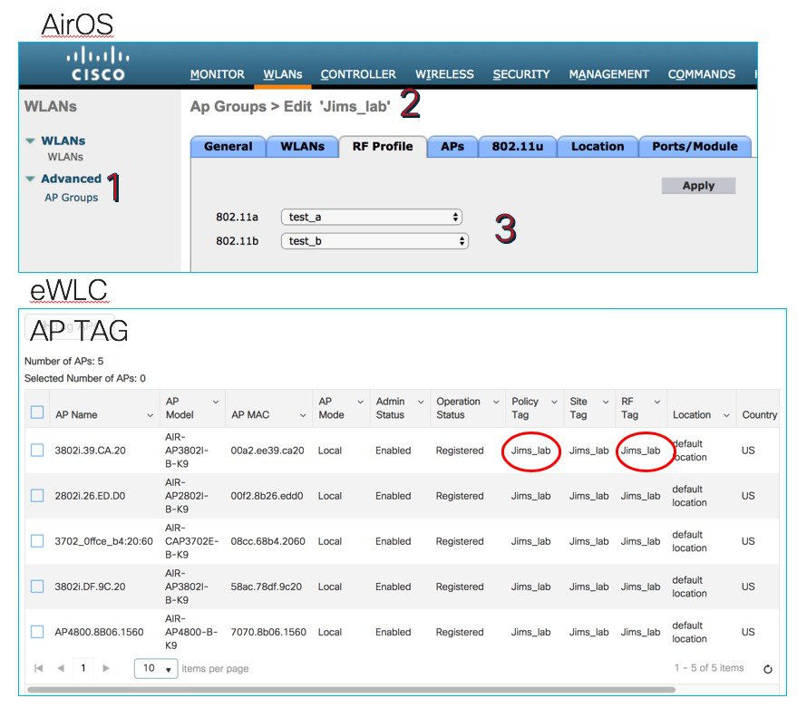
IOS XE Policies and Tag’s contained in IOS XE are also a distributed function between controllers and the RF Group. In order to join the two constructs (AireOS AP Groups and IOS XE Policies and tags) for RRM’s purposes, the names of the AP Groups must match the names of the:
-
The Policy Tag (which contains the Wlan Profile)
-
The RF Tag (Which contains the RF Profiles to be applied)
For example, for a given AP Group (Jims_lab) would need to create a Policy Tag, and an RF Tag using the name of Jims_lab. When we tag the individual AP,s with these three tags, we create the AP group with all of its components, and RRM won’t know the difference between IOS XE and AireOS.
Once you have created the 2 tags required, these are then applied to the individual AP’s that you want on each controller to participate in that “AP Group”. In Practice, this is fairly intuitive, just different that AireOS.
 Feedback