Configure and Troubleshoot MGCP Gateways

Available Languages
Contents
Introduction
This document describes how to configure and troubleshoot the Media Gateway Control Protocol (MGCP); MGCP is a Call Agent/Endpoint protocol.
Prerequisites
Requirements
There are no specific requirements for this document.
Components Used
- VG320
- Cisco Unified Communications Manager 11.5
The information in this document was created from the devices in a specific lab environment. All of the devices used in this document started with a cleared (default) configuration. If your network is live, ensure that you understand the potential impact of any command.
Background Information
Common Definitions
| Attribute |
Definition |
| Call Agent |
The Call Control elements that play the Primary role and provide centralized call intelligence. |
| Endpoints |
The Endpoints are the devices that the Call Agents control, such as: FXO, FXS, or a DS0 channel. |
| PSTN |
Public Switched Telephone Network. |
MGCP Fundamentals
The Media Gateway Control Protocol (MGCP) is defined by RFC 2705. The MGCP is a Call Agent/Endpoint protocol where the Endpoint is controlled by a Call Agent of some type. The entire control intelligence is managed by a Call Agent who instructs the endpoint what action to take once an event is detected. MGCP uses TCP port 2428 and UDP port 2427.
TCP port 2428 in MGCP is used to open a new socket with the Call Agent to determine if the connection can be established. Without this new socket, subsequent MGCP Messages cannot be exchanged. It is also used to Send/Receive Backhaul Messages between PRI Endpoints and the Call Agent it is registered to. Finally, TCP port 2428 is used to failover to backup Call Agents in the event a Primary Call Agent is unresponsive.
UDP port 2427 in MGCP is used for MGCP Messages exchanged between the Endpoints and Call Agents.
Basic Flow
This is an example of a basic MGCP Flow. In this example, the gateway receives a new call from the PSTN on this Voice Gateway (Endpoint). The Gateway notifies the Call Agent (CUCM) of this new call that is received, the Call Agent instructs the Gateway to create a connection for this new call. Finally, the Gateway sends an OK back to the Call Agent to establish the call.

Endpoint Identifiers
An identifier is needed per endpoint for the Call Agent to determine whom it needs to send an event, or where an event comes from. Endpoint Identifiers have two main components:
- Local Name within that Gateway (case insensitive).
- Domain Name of that Gateway that manages the endpoint (case sensitive).
Examples:
- AALN/S1/SU0/0@AV-VG200-2.cisco.com
- S0/SU0/DS1-0@AV-VG200-1
Basic Configuration of MGCP
This document has broken out each configuration components into individual steps.
Gateway CLI Configuration
On the Analog Gateway you plan to register to CUCM, this is the minimal configuration that is required. You only need to add this configuration to start the registration process, as the remaining configuration is downloaded from CUCM:
VG320(config)# mgcp call-agent 10.50.217.100 2427 service-type mgcp version 0.1
VG320(config)# ccm-manager config server 10.50.217.100
VG320(config)# ccm-manager config
VG320(config)# ccm-manager mgcp
VG320(config)# mgcp
**Note on the ISR4000s if you fail to down load your configuration file, you must add the command:
VG320(config)# ip tftp source-interface GigabitEthernet x/x/x
CUCM Configuration
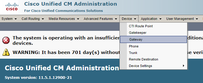
Step 1. To configure the MGCP Gateway in CUCM, you must log in to Cisco Unified CM Administration. Once logged in, navigate to Device > Gateway:
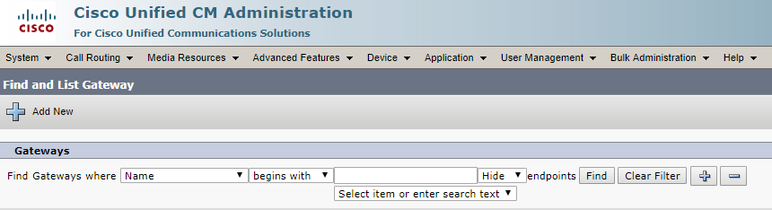
Step 2. The previous selection places you at the Find and List Gateway page. On this page, select the Add New button with a "+" (plus) sign:
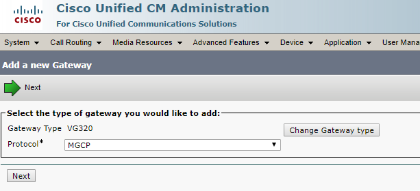
Step 3. After selecting Add New, you are prompted to choose a Gateway Type. Use the drop-down to choose the hardware you plan to register, and select Next to choose the protocol you want for this device (you must select MGCP):
Step 4. Once you have selected the hardware and protocol used, you must configure the Domain Name, the Cisco Unified Communications Manager Group, and the Module Information. These are the major fields that are required to register an endpoint via MGCP.
Step 5. The Domain Name is comprised of 1 to 2 parts. At a minimum in the Domain Name field, you must enter the Host Name of the router. In this scenario, the Host Name is:
VG320. However, if you have a domain name configured on the gateway, you must configure the Fully Qualified Domain Name of this device:
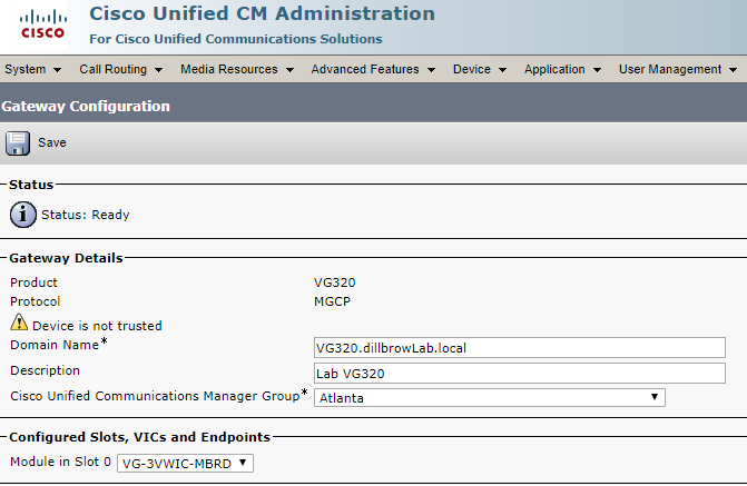
Step 6. Choose Save. This updates the page and allows you to select a Subunit. Once you select a Subunit, select Save again. You can now see your configurable ports:
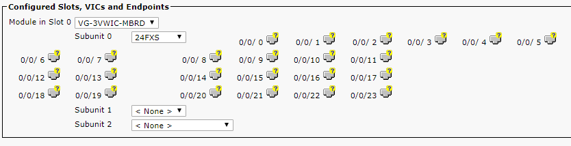
Step 7. To configure an endpoint, click the port your analog device is plugged into (in this scenario, it is 0/0/0). Once you select a port, you are prompted to configure the port type:
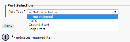
Step 8. In this case, select POTS. Once selected, you can enter all necessary values for the device information like you would for any other Call Manager Endpoint. The only required field is Device Pool, however, you can enter additional values such as the Calling Search Space. Once completed, click Save.
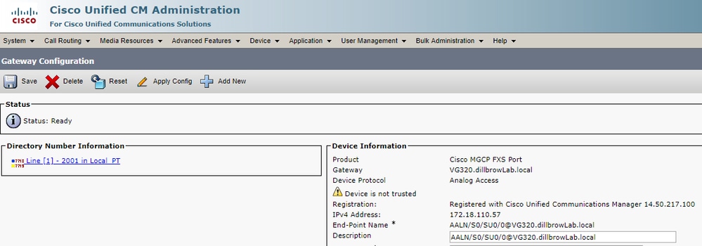
Step 9. At this point, the left-hand pane has populated the Add a New DN field You can now associate a DN with this port, save, and the apply the configuration. Once this is completed, back at the port configuration page you can see the port as registered:
Endpoint Registration and Call Setup
In this section, the basics of MGCP Endpoint Registration and Call Setup are covered. This includes the Command Messages seen as the Gateway interacts with the Call Agent. In this scenario, CUCM is our Call Agent.
MGCP Endpoint Registration
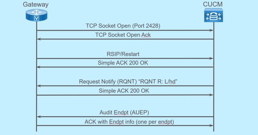
For an MGCP Endpoint to register to CUCM, the Gateway opens TCP socket 2428 to CUCM. From here, it uses UDP port 2427 to send command messages. Once the socket is open, the Gateway sends an RSIP Command to the CUCM to inform the Endpoint must be taken out of service while the restart occurs. The CUCM sends a simple acknowledgment on this. After the restart is complete, CUCM sends a RQNT with the parameter R: L/hd. What this does is denote the Gateway must notify CUCM of an off-hook event.
At this point, the CUCM sends an Audit Endpoint (AUEP) to the Gateway to determine the status of the given Endpoint. The response from the Gateway is an ACK with the endpoints capabilities. Once this is complete, the Endpoint is registered with the CUCM. This is a sample debug output:
000138: *Apr 23 19:41:49.010: MGCP Packet sent to <CUCM IP>:2427--->
RSIP 39380951 aaln/S0/SU0/0@VG320.dillbrowLab.local MGCP 0.1
RM: restart
<---

000139: *Apr 23 19:41:49.030: MGCP Packet received from <CUCM IP>:2427--->
200 39380951
<---

000140: *Apr 23 19:41:49.030: MGCP Packet received from <CUCM IP>:2427--->
RQNT 3 AALN/S0/SU0/0@VG320.dillbrowLab.local MGCP 0.1
X: 2
R: L/hd
Q: process,loop
<---

000141: *Apr 23 19:41:49.030: MGCP Packet sent to <CUCM IP>:2427--->
200 3 OK
<---

000142: *Apr 23 19:41:49.050: MGCP Packet received from <CUCM IP>:2427--->
AUEP 4 AALN/S0/SU0/0@VG320.dillbrowLab.local MGCP 0.1
F: X, A, I
<---

000143: *Apr 23 19:41:49.050: MGCP Packet sent to <CUCM IP>:2427--->
200 4
I:
X: 2
L: p:10-20, a:PCMU;PCMA;G.nX64, b:64, e:on, gc:1, s:on, t:10, r:g, nt:IN, v:T;G;D;L;H;R;ATM;SST;PRE
L: p:10-220, a:G.729;G.729a;G.729b, b:8, e:on, gc:1, s:on, t:10, r:g, nt:IN, v:T;G;D;L;H;R;ATM;SST;PRE
L: p:10-110, a:G.726-16;G.728, b:16, e:on, gc:1, s:on, t:10, r:g, nt:IN, v:T;G;D;L;H;R;ATM;SST;PRE
L: p:10-70, a:G.726-24, b:24, e:on, gc:1, s:on, t:10, r:g, nt:IN, v:T;G;D;L;H;R;ATM;SST;PRE
L: p:10-50, a:G.726-32, b:32, e:on, gc:1, s:on, t:10, r:g, nt:IN, v:T;G;D;L;H;R;ATM;SST;PRE
L: p:30-270, a:G.723.1-H;G.723;G.723.1a-H, b:6, e:on, gc:1, s:on, t:10, r:g, nt:IN, v:T;G;D;L;H;R;ATM;SST;PRE
L: p:30-330, a:G.723.1-L;G.723.1a-L, b:5, e:on, gc:1, s:on, t:10, r:g, nt:IN, v:T;G;D;L;H;R;ATM;SST;PRE
M: sendonly, recvonly, sendrecv, inactive, loopback, conttest, data, netwloop, netwtest
<---
MGCP Call Setup
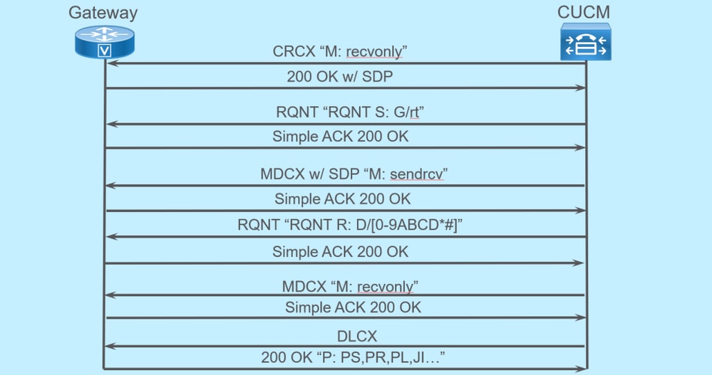
The previous image is an example of an outbound call.
You can see your Call Agent, in this case CUCM, starts with a CRCX that has recvonly to the Gateway to establish connection for the call. The Gateway responds back with a 200 OK that contains SDP for what it supports. Once this exchange is done, the CUCM sends an RQNT message to the Gateway with the parameter S: G/rt. This tells the Gateway to play ringback to the device. After the far end receives the call, and picks up, CUCM then sends a MDCX with SDP to the Gateway to let it know of the media information for the far end device. The Gateway sends back a simple 200 OK to acknowledge this, and at this point, you have established two-way media.
Now that the call has been answered, CUCM sends another RQNT with the parameter R: D/[0-9ABCD*#]. This tells the Gateway to let CUCM know of any DTMF that is pressed while the call is active, so it can be relayed to the next device.
Once the call is finished, CUCM sends an MDCX to the Gateway with M: recvonly to terminate the media, followed by a DLCX to disconnect the call. This is a sample debug output:
001005: *May 13 14:28:15.633: MGCP Packet received from <CUCM IP>:2427--->
CRCX 174 AALN/S0/SU1/0@VG320.dillbrowLab.local MGCP 0.1
C: A000000001b79063000000F5
X: 21
L: p:20, a:PCMU, s:off, t:b8
M: recvonly
R: L/hu
Q: process,loop
<---

001006: *May 13 14:28:15.637: MGCP Packet sent to <CUCM IP>:2427--->
200 174 OK
I: 6

v=0
c=IN IP4 <Gateway IP>
m=audio 16410 RTP/AVP 0 101 100
a=rtpmap:101 telephone-event/8000
a=fmtp:101 0-15
a=rtpmap:100 X-NSE/8000
a=fmtp:100 192-194
<---

001007: *May 13 14:28:15.789: MGCP Packet received from <CUCM IP>:2427--->
RQNT 175 AALN/S0/SU1/0@VG320.dillbrowLab.local MGCP 0.1
X: 22
R: L/hu
S: G/rt
Q: process,loop
<---

001008: *May 13 14:28:15.789: MGCP Packet sent to <CUCM IP>:2427--->
200 175 OK
<---

001009: *May 13 14:28:17.793: MGCP Packet received from <CUCM IP>:2427--->
MDCX 176 AALN/S0/SU1/0@VG320.dillbrowLab.local MGCP 0.1
C: A000000001b79063000000F5
I: 6
X: 23
L: p:20, a:PCMU, s:off, t:b8
M: sendrecv
R: L/hu, L/hf, D/[0-9ABCD*#]
S:
Q: process,loop

v=0
o=- 6 0 IN EPN AALN/S0/SU1/0@VG320.dillbrowLab.local
s=Cisco SDP 0
t=0 0
m=audio 18946 RTP/AVP 0 101
c=IN IP4 <Phone IP>
a=rtpmap:101 telephone-event
a=fmtp:101 0-15
<---

001010: *May 13 14:28:17.797: MGCP Packet sent to <CUCM IP>:2427--->
200 176 OK
<---

001011: *May 13 14:28:17.797: MGCP Packet received from <CUCM IP>:2427--->
RQNT 177 AALN/S0/SU1/0@VG320.dillbrowLab.local MGCP 0.1
X: 24
R: L/hu, D/[0-9ABCD*#], L/hf
S:
Q: process,loop
<---

001012: *May 13 14:28:17.797: MGCP Packet sent to <CUCM IP>:2427--->
200 177 OK
<---

001015: *May 13 14:28:20.813: MGCP Packet received from <CUCM IP>:2427--->
DLCX 178 AALN/S0/SU1/0@VG320.dillbrowLab.local MGCP 0.1
C: A000000001b79063000000F5
I: 6
X: 25
R: L/hd
S:
Q: process,loop
<---

001016: *May 13 14:28:20.845: MGCP Packet sent to <CUCM IP>:2427--->
250 178 OK
P: PS=151, OS=24160, PR=146, OR=23360, PL=0, JI=0, LA=0
<---
Troubleshoot MGCP
When you troubleshoot MGCP, there are some helpful show commands and debugs that you can view to determine why registration or a call has failed. A great place to start is to check if your MGCP Gateway is registered to the Call Agent. You can check by running the show command show ccm-manager or show mgcp:
VG320# show ccm-manager
MGCP Domain Name: VG320.dillbrowLab.local
Priority        Status                   Host
============================================================
Primary         Registered               <CUCM IP>
First Backup    None
Second Backup   None

Current active Call Manager:    <CUCM IP>
Backhaul/Redundant link port:   2428
Failover Interval:              30 seconds
Keepalive Interval:             15 seconds
Last keepalive sent:            17:42:40 UTC Jul 12 2019 (elapsed time: 00:00:15)
Last MGCP traffic time:         17:42:55 UTC Jul 12 2019 (elapsed time: 00:00:00)

VG320# show mgcp
MGCP Admin State ACTIVE, Oper State ACTIVE - Cause Code NONE
MGCP call-agent: <CUCM IP> 2427 Initial protocol service is MGCP 0.1
MGCP validate call-agent source-ipaddr DISABLED
MGCP validate domain name DISABLED
MGCP block-newcalls DISABLED
These commands have been shortened to contain just the pertinent output. For additional information, refer to these show outputs:
- show mgcp
- show mgcp endpoint
- show mgcp connection
- show ccm-manager
- show voice port summary
- show isdn status
- show controller [t1/e1] x/x/x
- show call active voice brief
- show voice call summary
- show voice call status
If the previous show commands check out, you can run these debugs on the device to further determine why your call has failed:
- debug mgcp [endpoint | error | events | packets]
- debug mgcp all (for advanced debugging)
- debug ccm-manager [backhaul | config-download | error | events]
- debug voip ccapi inout
- debug vpm signal
- debug voip vtsp session
- debug isdn q931
The previous debugs are a great place to start to troubleshoot registration and call setup issues.
Related Information
- RFC 2705: Data Tracker - Notification Request
Revision History
| Revision | Publish Date | Comments |
|---|---|---|
5.0 |
02-Jul-2026
|
Updated spelling, spacing, and 1 alt text. |
4.0 |
29-Aug-2023
|
Updated PII, SEO, Branding Requirements and Formatting. |
3.0 |
15-Jul-2022
|
Recertification |
1.0 |
14-Aug-2019
|
Initial Release |
 Feedback